IP: 185.13.32.102 On: Thu, 10 Jan 2019 11:29:41 Copyright: American Scientific Publishers
Delivered by Ingenta
Copyright © 2019 American Scientific Publishers All rights reserved
Printed in the United States of America
Article
Journal of Nanoscience and Nanotechnology Vol. 19, 492–497, 2019 www.aspbs.com/jnn
Preparing SnO 2 /MWCNT Nanocomposite Catalysts via High Energy Ball Milling
Krisztian Nemeth
1, Zoltan Pallai
1, Balazs Reti
1, Peter Berki
1, Zoltan Nemeth
12, and Klara Hernadi
1∗1Department of Applied and Environmental Chemistry, University of Szeged, Rerrich tér 1, Szeged H-6720, Hungary
2Institute of Chemistry, University of Miskolc, Miskolc-Egyetemváros, Miskolc, H-3515, Hungary
Ball milling method was used to fabricate successfully tin dioxide (SnO2/multi-walled carbon nano- tubes nanocomposite materials using SnCl2×2H2O as precursor together with soda and salt as admixture. The as-prepared materials were characterized by transmission electron microscopy, scanning electron microscopy with energy-dispersive X-ray spectroscopy, Raman microscopy, and X-ray diffraction techniques. Observations revealed that applying both soda and salt are advanta- geous for increasing dispersity of tin dioxide nanoparticles on the surface of carbon nanotubes.
These multi-walled carbon nanotube-based composites are promising candidates as thick film gas sensors or catalysts. Results indicate that SnO2/MWCNT composites can be achieved under solvent free dry conditions, too.
Keywords: Carbon Nanotubes, Tin Dioxide, Dry Ball Milling, Nanocomposite.
1. INTRODUCTION
Due to their excellent physical, mechanical, and unique electronic properties, carbon nanotubes (CNTs) have affected research community since their discovery.1CNTs are considered as capable contestants for many appli- cations such as composite materials,2 field emission materials3 or chemical sensors.45 Combining CNTs with various nanoparticles can result in exceptional per- formances in solar cells, catalysts or nanoelectronic devices.6–9 Due to their high theoretical electrical conduc- tivity, high aspect ratio and good mechanical properties, carbon nanotubes can offer the necessary electronic matrix for anode materials.10
From recent investigations, it can be learned that the attachment of various inorganic compounds such as SnO2 onto single-walled (SWCNTs) or multi-walled carbon nanotubes (MWCNTs)411–14 can be achieved via different synthesis methods. MWCNTs were decorated with SnO2 by the chemical solution method in which acid-treated MWCNTs was used.15Zhu et al.16reported the preparation of MWCNT/SnO2core–shell structures by a double coat- ing process in a wet chemical route. Du et al. synthesized SnO2nanotubes on CNTs by a layer-by-layer technique.17 In some preliminary experiments, it has been observed that
∗Author to whom correspondence should be addressed.
SnO2nanoparticles could be deposited onto the surface of MWCNTs to form a uniform layer by CVD technique.12
As one of the most important semiconductor oxide, SnO2 has been studied using for different purposes such as photocatalysts,1819 lithium ion batteries20 or sensors.21 On the other hand, MWCNT could be considered as a good electron acceptor because of its unique structure.22 Beyond potential photocatalytic efficiency,23several papers were already published about special sensing applications.
For the efficient detection of SO2gas, MWCNT-SnO2 and RGO-SnO2 hybrid nanocomposite sensors were prepared by incorporating MWCNTs and RGO (reduced graphite oxide) into SnO2 nanoparticle colloidal solution respec- tively by chemical route.24Pal et al.25achieved high sensi- tivity, stability, ultrafast response toward sub-ppm acetone detection with a good resolution (i.e., promising material for diabetes sensor) just by using MWCNTs as a sub- strate for nanocrystalline SnO2 prepared through a facile sol–gel technique. In our previous investigations, we suc- cessfully fabricated SnO2/MWCNT nanocomposite by the sol–gel method and their gas sensing properties were also studied.2627
In order to exploit good electricity of MWCNT and semiconductor properties of SnO2, the aim of current work was to develop controllable synthesis method for SnO2/MWCNT composites. Since our former results
IP: 185.13.32.102 On: Thu, 10 Jan 2019 11:29:41 Copyright: American Scientific Publishers
Delivered by Ingenta
2
proved28 that using either impregnation or hydrothermal synthesis the morphology of composite is strongly influ- enced by the applied solvents. Thus, in order to investigate the previously mentioned parameters, we applied solvent free method via planetary ball milling. The morphology of the final product was investigated: beside vulnerability of MWCNT under milling conditions, the effect of “inert”
compounds on the structure of the final product was also studied.
2. EXPERIMENTAL DETAILS
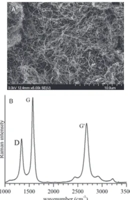
MWCNT was prepared from acetylene (CVD method) in a rotary oven at 720C using Fe, Co/CaCO3catalyst.29This synthesis method using CaCO3 catalyst enables a highly efficient selective growth of MWCNT having a clean sur- face, free of any amorphous carbon or carbonaceous parti- cles, thus suitable for effective bonding between MWCNT and precursors (see Fig. 1). High graphitization also pre- vents pristine MWCNT from fragmentation under mechan- ical stress during ball milling.
Fritsch Pulverisette 6 type planetary ball mill, equipped with a 250-mL grinding bowl and 10 WC balls of 10 mm size were used for homogenization. The rotational speed was 400 rpm. In order to avoid damage of MWCNT, the treatment time of planetary ball milling was set to a low value, namely 60 minutes.
In the first series, SnCl2 (SnCl2×2H2O from Molar Chemical) was added as precursor together with MWCNT for the preparation of composites, using a mass ratio of
A
B
Figure 1. SEM micrograph (A) and Raman spectrum (B) of pristine MWCNTs.
8:1. To form SnO2 directly during ball milling,30 Na2CO3 (soda, Reanal) was also added to the system in the sec- ond series (the presence of soda is denoted in superscript before the name of the composite):
SnCl2+Na2CO3→SnO+2NaCl+CO2
To avoid aggregation of forming SnO2nanoparticles, in the third series NaCl (salt, Spektrum-3D) was also placed into the bowl before milling (the presence of salt is denoted in subscript before the name of the composite). For better comparison of SnO2 nanoparticles, each sample was pre- pared without carbon nanotubes, too. The formed and/or added NaCl was washed off with distilled water from the system after milling.
The following components were mixed in the bowl:
SnCl2 with or without MWCNTNa2CO3 NaCl in 111 molar ratio
and the samples were denoted as follows:
soda
saltSnO2/MWCNT
Samples were heat treated in air at 450C for 3 hours.
Under the most promising conditions, the SnO2/ MWCNT mass ratio was reduced to 4:1 and 2:1 hoping that the portion of segregated SnO2 can be controlled in this way.
In order to verify the formation of any decoration on the surface of MWCNTs, the resulted powders were investi- gated with transmission electron microscopy (Philips CM 10, FEI Technai G220 X-TWIN (TEM)). A small amount of sample was sonicated in ethanol. A few drops of this suspension were dribbled onto the surface of the cop- per grid. Scanning electron microscopy (Hitachi S-4700 Type II (SEM)) with a Röntec XFlash Detector 3001 SDD device was used to identify tin oxide nanoparticles. The crystalline structure of the inorganic layer was also stud- ied by powder X-ray diffraction—XRD—(Rigaku Miniflex II Diffractometer) method using Cu Kradiation. Raman spectroscopy measurement was done on a Thermo Scien- tific DXR Raman microscope with a 532 nm laser (5 mW).
3. RESULTS AND DISCUSSION 3.1. X-ray Diffraction Characterization
To ascertain the crystallinity, all samples were character- ized by XRD technique. However, because of significant similarities, only one diffraction pattern is presented in the current study. On the X-ray diffraction patters the char- acteristic diffractions of SnO2 can be identified, namely, 2 =265—(110), 33.8—(101), 37.9—(200), 51.8— (211), and 54.6—(220). Approximately at 2=25 a shoulder can be seen which is most presumably the char- acteristic reflection of MWTNs. Since crystal plane (002)
IP: 185.13.32.102 On: Thu, 10 Jan 2019 11:29:41 Copyright: American Scientific Publishers
Delivered by Ingenta
2
Figure 2. X-ray diffractogram of sodaSnO2/MWCNT nanocomposite after ball milling of SnCl2, Na2CO3and MWCNT.
of multi-walled carbon nanotubes and reflection (110) of SnO2 overlap, their identification is ambiguous by means of X-ray diffraction. The distinctive X-ray diffraction pat- tern of NaCl is not detectable; thus, only traces of this material can be present in the samples. Hence, X-ray diffraction results confirmed that crystalline SnO2 can be obtained via ball milling of SnCl2 precursor. Figure 2 illustrates characteristic reflections of sodaSnO2/MWCNT nanocomposite obtained after ball milling of SnCl2, Na2CO3 and MWCNT together. In addition to the above mentioned diffraction peaks, a broad reflection appears at around 2=30 and a noticeable shoulder at around 2=35. These features can be attributed to the presence of Na2CO3.
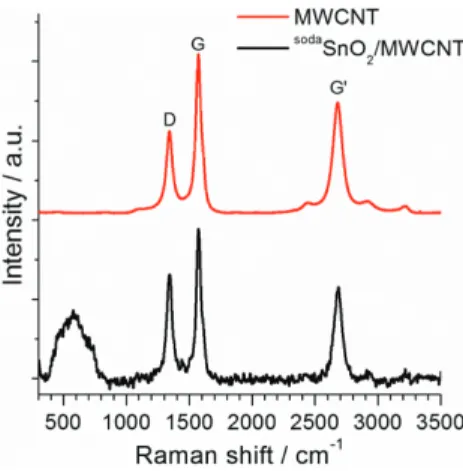
3.2. Raman Microscopy Measurements
In order to resolve former uncertainties, Raman microscopy measurements were also implemented. From Raman spectra in Figure 3 conclusions can be drawn refer- ring to the nature of both constituents and final nanocom- posites. Regarding multi-walled carbon nanotubes, Raman spectra verified their good quality of high degree of graphitization. From D, G and G peaks (see Table I)
Figure 3. Raman spectra of pristine MWCNT and sodaSnO2/MWCNT nanocomposite after ball milling of SnCl2, Na2CO3and MWCNT.
Table I. Raman intensity ratios of pristine MWCNT and SnO2/MWCNT.
MWCNT SnO2/MWCNT
ID/IG 0.51 0.69
IG/IG 0.70 0.58
IG/ID 1.35 0.84
well-graphitized structure of pristine MWCNT is proved, moreover, change in intensity ratios of SnO2/MWCNT nanocomposite suggests a minor change in the structure of MWCNT which can be correlated with the forming chemical bond between constituents. The possibility that this minor change is coming from the damage caused by ball milling can be excluded by our former results.31Since there is a broad peak in the region of 400 cm−1 and 800 cm−1, identification of SnO2 from Raman spectra is unfortunately doubtful. Characteristic peak of SnO2 could be expected at around 630 cm−1but it is probably covered by the sign of semi-crystalline SnO(OH)2. However, this observation is in accordance with X-ray diffraction results described above.
3.3. Energy Dispersive X-ray Analysis
In order to characterize the quality of nanoparticles in as- prepared samples, energy dispersive X-ray analysis (EDX) was performed in the SEM instrument for each nanocom- posite. Since EDX spectra showed significant similarity, only one EDX spectrum is presented here (Fig. 4). The most important signals originate from carbon (C) oxy- gen (O) and tin (Sn), respectively, which proves the con- stituents of nanocomposites. It is worthy notified that no sodium peak was detectable, thus removal of NaCl from the sample was successful.
3.4. Transmission Electron Microscopy Investigations Transmission electron microscopy revealed that mate- rials, obtained without admixture, e.g., ball milling of tin chloride precursor and MWCNT, possess non- uniform morphology. Figure 5 shows TEM micrographs for SnO2 crystals after ball milling of SnCl2 (A) and SnO2/MWCNT nanocomposite after ball milling of SnCl2 and MWCNT (B), respectively. In Figure 5(A) both small
Figure 4. Representative EDX analysis ofsodaSnO2/MWCNT nanocom- posite after ball milling of SnCl2, Na2CO3and MWCNT.
IP: 185.13.32.102 On: Thu, 10 Jan 2019 11:29:41 Copyright: American Scientific Publishers
Delivered by Ingenta
2
A B
Figure 5. TEM images of SnO2 crystals after ball milling of SnCl2 (A) and SnO2/MWCNT nanocomposite after ball milling of SnCl2 and MWCNT (B).
crystals and nanorods can be observed. Shearing stress during high energy ball milling might affect the shape of forming SnO2 crystals; therefore we applied sim- ple heat treatment and made sure of the formation of nanorods via annealing. This is in accordance with for- mer investigations,32 which resulted in SnO(2) nanowires and nanorods were one dimensional (1D) structures with widths and lengths of 50–200 nm and several microm- eters, respectively. From the analysis of TEM images of nanocomposites (Fig. 5(B)), it can be stated that MWCNT is strongly damaged, fragmented, and forming SnO2nanoparticles are not deposited onto its surface rather form segregated clusters. We suppose that without admix- ture SnCl2 precursor can form very reactive chlorine- containing species during ball milling which react with MWCNT (the only reaction partner in the present instance) in the milling bowl. Due to significant fragmentation and
A B
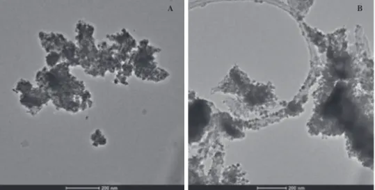
Figure 6. TEM images ofsodaSnO2crystals after ball milling of SnCl2and Na2CO3(A) andsodaSnO2/MWCNT nanocomposite after ball milling of SnCl2, MWCNT and Na2CO3(B).
low SnO2 coverage observed, further experiments were carried out under modified conditions.
The presence of admixture, e.g., can hinder undesirable effects, as chemical reaction between SnCl2 and Na2CO3 result in less reactive by-products such as NaCl and CO2. Accordingly, the following samples were prepared with three constituents. From TEM image of sodaSnO2 crystals in Figure 6(A) it can be seen that nano-sized SnO2particles form bigger aggregates, however, nanorods cannot be observed any more. TEM investigations also revealed that in sodaSnO2/MWCNT nanocomposite there are undamaged multi-walled carbon nanotubes (with no fragmentation and unvarying aspect ratio) densely covered by SnO2 nanoparticles (Fig. 6(B)). Nevertheless, beside
sodaSnO2/MWCNT nanocomposite significant amount of separated SnO2 aggregates like the one described in Figure 6(A) was detected. These bigger particles can
IP: 185.13.32.102 On: Thu, 10 Jan 2019 11:29:41 Copyright: American Scientific Publishers
Delivered by Ingenta
2
A B
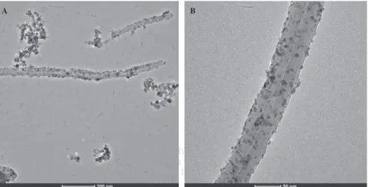
Figure 7. TEM images ofsodasaltSnO2crystals after ball milling of SnCl2, Na2CO3and NaCl (A) andsodasaltSnO2/MWCNT nanocomposite after ball milling of SnCl2, MWCNT, Na2CO3and NaCl (B).
A B
Figure 8. TEM images ofsodaSnO2/MWCNT nanocomposite prepared with 4:1 (A) and 2:1 (B) mass ratio.
even enshroud desired nanocomposites. This experience inspired us to further modify experimental conditions.
In the hope of avoiding the formation of segregated particles, another admixture (e.g., inert NaCl) was added to the system. In the case of sodasaltSnO2 crystals it can be concluded from TEM observations (Fig. 7(A)) that aggregation was successfully suppressed. In the case of
sodasaltSnO2/MWCNT nanocomposite (see Fig. 7(B)) multi- walled carbon nanotubes decorated with SnO2 nanoparti- cles formed again, however, the amount of separated SnO2 phases was not reduced significantly.
From TEM analysis it can be concluded that both
sodaSnO2/MWCNT andsodasaltSnO2/MWCNT nanocompos- ites contained the desired ensemble thus they are worthy for further experiments.
3.5. Tuning Mass Ratio of SnO2and MWCNT
In order to reduce the amount of segregated SnO2 par- ticles, synthesis conditions were modified as follows:
SnO2:MWCNT mass ratio was reduced to 4:1 and 2:1, respectively, and ball milling was carried out in the pres- ence of Na2CO3 admixture. TEM images in Figures 8(A)
and (B) illustrates well that using mass ratio of 4:1
sodaSnO2/MWCNT nanocomposite is still accompanied together by separated SnO2 particles, however, their amount is already significantly lowered. On the other hand, with the mass ratio of 2:1 (Fig. 8(B)) the sep- aration of SnO2 nanoparticles is completely inhibited.
Summing up of our observations it can be stated that choosing proper mass ratio of SnO2:MWCNT, high energy ball milling is a suitable method for the fabrication of SnO2/MWCNT nanocomposite. With lower mass ratio fur- ther benefit can be gained: former investigations revealed that for (photo)catalytic purposes a non-homogeneous cov- erage is advantageous.33
4. CONCLUSION
The aim of this work was to produce SnO2/MWCNT nanocomposite under solvent free conditions via high energy ball milling for homogenization. SnCl2 and MWCNT were used as starting materials—with or with- out admixture(s)—under different synthesis conditions.
Physico-chemical characterization revealed that the addi- tion of admixture(s) and the MWCNT content of the
IP: 185.13.32.102 On: Thu, 10 Jan 2019 11:29:41 Copyright: American Scientific Publishers
Delivered by Ingenta
2
synthesis mixture significantly affected the morphology of final products. While the crystal structure was rather independent of the nature of initial compounds (from the results of XRD diffraction, Raman microscopy and energy-dispersive X-ray spectroscopy), transmission elec- tron microscopy analysis confirmed that components have a strong influence on the morphological feature of the nanocomposite. Without admixtures, the structure of multi- walled carbon nanotubes severely damaged, probably due to the formation of aggressive chemicals from the tin pre- cursor. Applying soda or soda and salt together prevented MWCNT from significant fragmentation, thus proved to be suitable methods for SnO2/MWCNT nanocomposite synthesis. NaCl, either formed or added, can be eas- ily and successfully removed from the product; however, to reduce the amount of segregated SnO2 particles only
sodaSnO2/MWCNT nanocomposites were prepared with different mass ratios. Using SnO2:MWCNT mass ratio of 2:1 resulted in “clean” SnO2/MWCNT nanocompos- ite without segregated inorganic particles. It was proved that unbeneficial effect of various solvents can be avoided by another synthesis technique. Changing admixtures and mass ratios during high energy ball milling, both the mor- phology and the composition of the final product can be controlled. Furthermore, these shape tailored materials are rather promising for future application in many fields such as effective (photo)catalysis or special sensing.
Acknowledgment: Special thanks to Professor László Forró and his research group in École Polytechnique Fédérale de Lausanne (EPFL) to provide us the multi- walled carbon nanotubes. This work was supported by grants from Switzerland through Swiss Contribution (SH/7/2/20). Klara Hernadi is very grateful for the finan- cial support provided by the GINOP-2.3.2-15-2016-00013 project. Krisztian Nemeth thanks to Országos Tudományos Kutatási Alapprogramok (OTKA NN114463) to finan- cial support. Zoltan Nemeth is thankful for the finan- cial support for the European Union and the Hungarian Government in the framework of the GINOP 2.3.4-15- 2016-00004 “Advanced materials and intelligent tech- nologies to promote the cooperation between the higher education and industry.”
References and Notes
1. S. Iijima,Nature354, 56(1991).
2. H. B. Chu, L. Wei, R. L. Cui, J. Y. Wang, and Y. Li,Coord. Chem.
Rev.254, 1117(2010).
3. S. Frank, P. Poncharal, Z. L. Wang, and W. A. de Heer,Science 280, 1744(1998).
4. Y. L. Liu, H. F. Yang, Y. Yang, Z. M. Liu, G. L. Shen, and R. Q.
Yu,Thin Solid Films497, 355(2006).
5. M. T. Humayun, R. Divan, Y. Z. Liu, L. Gundel, P. A. Solomon, and I. Paprotny,J. Vac. Sci. Technol. A34, 7(2016).
6. H. Y. Dong and K. Lu,Int. J. Appl. Ceram. Technol.6, 216(2009).
7. P. Diao and Z. F. Liu,J. Phys. Chem. B109, 20906(2005).
8. G. H. Jiang, X. Y. Zheng, Y. Wang, T. W. Li, and X. K. Sun,Powder Technol.207, 465(2011).
9. D. R. Kauffman, Y. F. Tang, P. D. Kichambare, J. F. Jackovitz, and A. Star,Energy Fuels24, 1877(2010).
10. B. J. Landi, M. J. Ganter, C. D. Cress, R. A. DiLeo, and R. P.
Raffaelle,Energy Environ. Sci.2, 638(2009).
11. W. Q. Han and A. Zettl,Nano Lett.3, 681(2003).
12. Q. Kuang, S. F. Li, Z. X. Xie, S. C. Lin, X. H. Zhang, S. Y. Xie, R. B. Huang, and L. S. Zheng,Carbon44, 1166(2006).
13. G. D. Du, C. Zhong, P. Zhang, Z. P. Guo, Z. X. Chen, and H. K.
Liu,Electrochim. Acta55, 2582(2010).
14. C. Q. Feng, L. Li, Z. P. Guo, and H. Li,J. Alloys Compd.504, 457 (2010).
15. C. H. Xu, J. Sun, and L. Gao,J. Phys. Chem. C113, 20509(2009).
16. C. L. Zhu, M. L. Zhang, Y. J. Qiao, P. Gao, and Y. J. Chen,Mater.
Res. Bull.45, 437(2010).
17. N. Du, H. Zhang, B. D. Chen, X. Y. Ma, X. H. Huang, J. P. Tu, and D. R. Yang,Mater. Res. Bull.44, 211(2009).
18. M. Dimitrov, T. Tsoncheva, S. F. Shao, and R. Kohn,Appl. Catal.
B-Environ.94, 158(2010).
19. S. Zaman, K. Zhang, A. Karim, J. G. Xin, T. Sun, and J. R. Gong, Diam. Relat. Mat.76, 177(2017).
20. H. W. Song, N. Li, H. Cui, and C. X. Wang, Electrochim. Acta 120, 46(2014).
21. H. J. Zhang, Z. J. Tan, P. P. Xu, K. Oh, R. F. Wu, W. M. Shi, and Z. Jiao,J. Nanosci. Nanotechnol.11, 11114(2011).
22. Y. Sun, S. R. Wilson, and D. I. Schuster, J. Am. Chem. Soc.
123, 5348(2001).
23. N. Wang, J. X. Xu, and L. H. Guan, Mater. Res. Bull. 46, 1372 (2011).
24. P. Tyagi, A. Sharma, M. Tomar, and V. Gupta, Sens. Actuator B-Chem.248, 980(2017).
25. M. Narjinary, P. Rana, A. Sen, and M. Pal,Mater. Des.115, 158 (2017).
26. V. M. Aroutiounian, V. M. Arakelyan, E. A. Khachaturyan, G. E.
Shahnazaryan, M. S. Aleksanyan, L. Forro, A. Magrez, K. Hernadi, and Z. Nemeth,Sens. Actuator B-Chem.173, 890(2012).
27. V. M. Aroutiounian, A. Z. Adamyan, E. A. Khachaturyan, Z. N.
Adamyan, K. Hernadi, Z. Pallai, Z. Nemeth, L. Forro, A. Magrez, and E. Horvath,Sens. Actuator B-Chem.177, 308(2013).
28. Z. Németh, Z. Pallai, B. Réti, Z. Balogh, O. Berkesi, G. Veréb, A. Dombi, and K. Hernadi,J. Coat. Sci. Technol.1, 137(2014).
29. E. Couteau, K. Hernadi, J. W. Seo, L. Thien-Nga, C. Miko, R. Gaal, and L. Forro,Chem. Phys. Lett.378, 9(2003).
30. G. Kozma, A. Kukovecz, and Z. Konya,J. Mol. Struct. 834, 430 (2007).
31. Z. Nemeth, B. Reti, Z. Pallai, P. Berki, J. Major, E. Horvath, A. Magrez, L. Forro, and K. Hernadi,Phys. Status Solidi B-Basic Solid State Phys.251, 2360(2014).
32. S. H. Mousavi, H. Haratizadeh, and P. W. de Oliveira,J. Nanosci.
Nanotechnol.11, 8233(2011).
33. B. Reti, N. Peter, A. Dombi, and K. Hernadi, Phys. Status Solidi B-Basic Solid State Phys.250, 2549(2013).
Received: 22 September 2017. Accepted: 5 December 2017.