Ronald Lang"* and Barry Lubin' Hamilton Standard,
Division of United Aircraft Corporation, Windsor Locks, Conn.
Abstract
A review of a modular solar thermoelectric power supply sys- tem which includes thermal energy storage and orientation de- vices is made. Incorporation of concepts outlined here is ex^
pected to contribute to long life requirements of communication and weather satellites. A comparison of thermal storage with other systems for supplying continuous power is presented.
Introduction
In the year that has elapsed since the authors reported on the results of feasibility testing of a solar thermoelectric generator, continued effort has been directed toward the selec- tion and evaluation of efficient and practical methods of en- ergy storage and orientation. These two problems are not the only areas that require additional attention before long life, high reliability missions can be achieved. Studies must be made of the decay of high reflectivity surfaces with time, the effect of time and cycling on thermocouple junctions, the effect of high energy radiation on thermocouple performance, subli- mation of vital materials in space vacuum, and others. The answers to these latter problem areas can only come with experi- ment and development. There are varied approaches to solutions which appear to be well founded and many of these can be found in the literature. However, because there have not yet been demonstrated reliable long life energy storage and array ori- entation schemes, the work reported herein has been directed Presented at the ARS Space Power Systems Conference, Santa Monica, California, September 25-28,1962. The authors would like to acknowledge the work of F. R. Emmons and the late Samuel J. Loring of Hamilton Standard Division of United Air- craft Corporation, in the preparation of this paper.
* Senior Analytical Engineer, Research Department.
TAnalytical Engineer, Research Department.
along these lines.
Because the expenses involved in putting a satellite into orbit are tremendous, it is imperative to achieve high relia- bility and long life. A five-year mission has been set down as a guideline. Moreover, a low orbit (ЗОО miles) with an average shade time of 35 min. has also been stipulated.
Comparison of Storage Systems
For a mission of long duration with alternating periods of light and dark operation, some means of energy storage or non- sunlight-dependent operation must be considered. Various types of energy producing devices are possible, but for a low power, light weight satellite only certain types merit consideration.
Such systems include solar thermoelectric with batteries^, iso- topic thermoelectric^, thermal storage thermoelectric^-, and
solar cells with batteries.-^ '' A comparison of the relative merits of each of these systems can be made on a specific weight
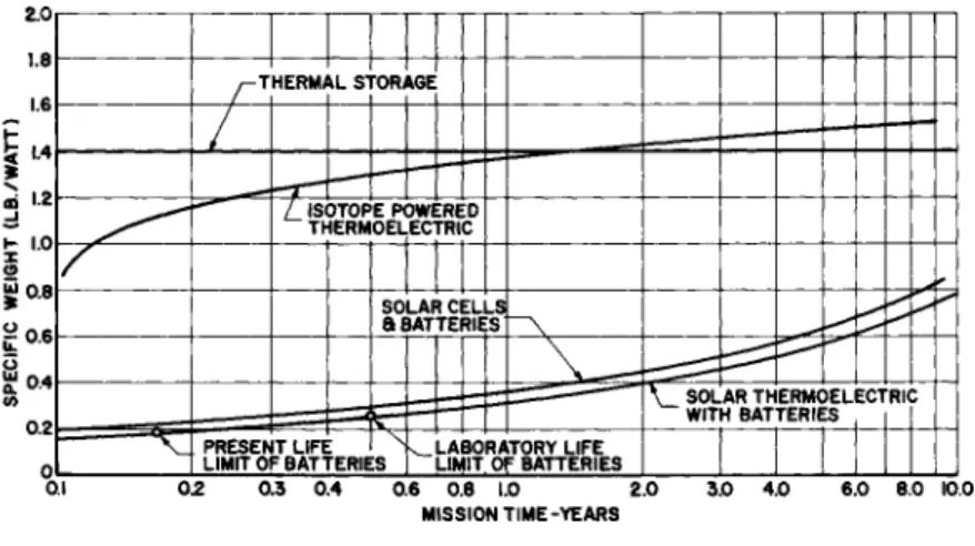
(lb/w) vs mission length basis. Figure 1 shows the results on this general comparison. This figure was constructed from a general survey of the field not taking into account problem areas which exist in each system.
As indicated in Figure 1, solar thermoelectric generators with batteries have the lowest specific weight. The limiting factor here is battery life. Present state of the art limits battery life to approximately 1000 cycles, though laboratory tests indicate 3OOO cycles could be achieved in the near fut- ure. These figures are dependent on depth of charge, discharge rate and other operating parameters. The life of a solar cell system also depends on battery life. Both of these systems have other life-limiting probeIsm of a similar nature which must be solved. However, battery life is the limiting factor.
Isotope power generators using isotopes such as Curium-2^-2 have specific powers greater than solar operating systems^ and do not have the restriction of limited battery life. However, present state of the art indicates that unless longer lived high power density isotopes become available, specific power will rise quite rapidly, breaking even with the thermal storage at approximately a 1.5 yr mission. Thermal storage, while having a high specific weight, shows promise of being the only device capable of long mission life. Problem areas such as mete- oroid particle and showers, Van Allen radiation effect, etc.
must be evaluated, yet they are of the same order magnitude as development problems associated with other systems. Once per- fected to an acceptable degree of reliability, thermal storage has the advantage of prolonged mission life, since it is not
limited Ъу self-consummation of its power-producing capability.
Battery storage, on the other hand, should not be discounted because of the relatively short life. There can be no doubt that laboratory equipment will soon become prototype equipment.
Thus in the near future 3OOO cycle life will be attainable.
When and if this can be increased to 250OO cycles is open to question. If rechargeable batteries can be developed to sat- isfy the requirements stipulated herein, they will be an ex- tremely attractive expedient.
Thermal Energy Storage
For operation while in the shadow of the earth, a solar power supply for a satellite must incorporate some means of energy storage. For very long missions, the simplicity, inherent reliability, and very high charge-discharge cycle potential of thermal energy storage make this method attractive.
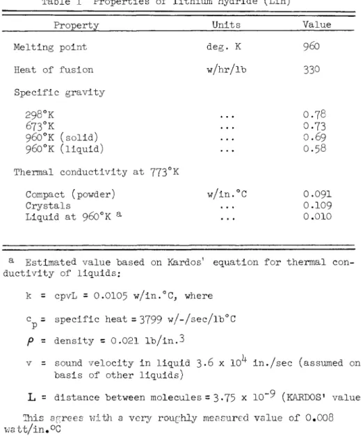
Studies have indicated that the heat of fusion of lithium hydride, 330 w-hr/lb, makes it one of the best materials for heat storage. Although the melting temperature of 9бО°К is considerably higher than the 600°K hot junction temperature established later in the present article, the very high heat of fusion makes this material desirable. The properties of lithium hydride are listed in Table 1.
The principal problems involved in the use of lithium hydride for energy storage arise from the properties of the material itself. Lithium hydride is corrosive to many materials, par- ticularly at elevated temperatures and in the liquid state. It is reported, however, the LiH can be contained in 316 stainless steel and is stable up to more than 73°C above its melting point, or 1033°K. At higher temperatures some dissociation takes place, and hydrogen can be lost by diffusion through the
container.
A 300-mile-altitude satellite in a polar orbit has a revolu- tion period of about 90 min. Depending on the position of the earth in Its orbit around the sun, the dark time per orbit revolution of the satellite can vary from zero to 35 min. The energy storage system must be designed to provide heat for operation of the generator for 35 min. after a period of 55 min.
of sunlit operation. In order to prevent overheating of the lithium hydride and the thermoelectric materials when the dark time Is less than 35 min., some form of temperature control will be required.
A second problem encountered in the use of lithium hydride
for thermal energy storage results from the very low thermal conductivitity of LiH in the liquid state, estimated in Table 1 The temperature rise in the LiH at the end of the heating in- terval must not he excessive as this would cause decomposition of the LiH.
Basic Unit Cell Design and Performance
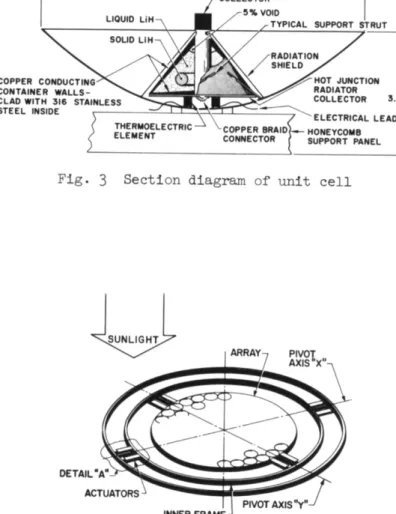
The basic unit cell design with integral thermal energy storage is shown in Figures 2 and 3« The size and proportions of the design have Ъееп determined Ъу an optimization study in conjunction with the mission requirements previously outlined.
As indicated in Figure 3* the unit cell reflector in 8 in. in diameter; the reflector dish is made of aluminum and tapers in thickness from О.ОбО in. at the center to 0.007 in. at the rim.
The thermal storage capsule is conical with thick, uniform conduction area copper walls and an integral cylindrical copper collector and central conduction rod. The primary purpose of the copper is to conduct heat to and from all sides of the LiH which, particularly in the liquid state, has a very low thermal conductivity. Heat transfer to and from the thermal storage medium will he discussed in greater detail in the next section.
The LiH itself must he contained in #3l6 stainless steel with which it is nonreactive. Copper walls in contact with LiH are clad with 0.010 in. stainless steel welded gas tight and hrazed or cemented to the copper conducting walls and rod.
Although the outside copper conducting surface of the LiH container has heen found necessary for heat transfer purposes, it will also serve as meteorite puncture protection and will reduce the possibility of hydrogen loss Ъу diffusion.
According to the data on diffusion of gases through metals10 the diffusion rate of hydrogen through copper is l/lOO to l/20 of the rate to he expected through stainless steel based on the diffusion rate in iron and nickel.
The collector surface is a cylinder 0 Л 0 in. in diameter and O.UO in. long. The collector is coated with a selectively emissive coating such as that produced by multiple evaporated coatings alternatively of CiO and Al. If it is necessary to protect this coating from space environment to maintain emissive properties over long time periods, the cylindrical collector surface could be covered by a fused quartz cylindrical window.
The external copper surface of the LiH container is highly polished to achieve a low emissivity of about 0.02 at its operating temperature. In addition, a conical radiation shield
of 0.010 in. copper is mounted on the reflector and surrounds the conical container surface. This shield has a low emissivity inner surface for radiation shielding and a high emissivity outer surface to radiate the heat that it does receive.
The thermal energy storage capsule is supported Ъу three pairs of struts in "V" configuration which run from the cone surface through the reflector dish. These struts, as indicated in Fig.
3, are about 1.25 in. long and are made of 0.025 in. stainless steel wire; they are brazed into slots cut in conical copper surface and are soldered into holes in the reflector dish.
In the proposed design, two pairs of thermocouple elements, comprising two thermocouples in series, are mounted on the re- flector dish under the base of the thermal energy storage cone.
Heat is transferred to the hot junctions Ъу radiation from the cone base to each of four quadrant shaped 0.010 in. thick col- lectors mounted directly on the hot face of the thermoelements using the temperature drop from about 9б0°К of the cone to the 600°K hot junction temperature. The necessary electrical con- nections between hot junction radiation collectors are made with flexible copper braids so that the hot junction of each thermoelement is substantially free, eliminating thermal stres- ses .
Cold junctions of the thermoelements are mounted in thermal contact with, but electrically insulted from, a flat portion at the center of the reflector dish. Ribbon electrical conductors run from the cold junctions through slits in the reflector dish to connect with other unit cells.
The complete assembly, consisting of reflector, radiation collector, thermal energy storage capsule and thermocouple, is constructed so that the collector lies at the focal point of the reflector. Outside the flat center portion of the reflector dish where the thermoelements are mounted, there is an annular portion, shaded by the heat storage capsule, which is spherical in shape. The spherical portion of the reflector dish is ce- mented to a spherical ring seat on the support panel so that the axis of the parabolic reflector can be made to coincide with the optical axis of a subarray panel during final assem- bly of the panel.
A heat balance for a unit cell for a 55 min. sunlit-35 min.
dark orbit is presented in Table 2. Comparison of items 3e and 3f shows that during sunlit operation heat enters the ther- mal energy storage capsule at a rate of 29.0-17-7 - H-3 w.
For effective temperature control, at least 11.3 w of additional heat must be rejected from the capsule directly to space when
90% of the lithium hydride mass have melted in a completely sunlit orbit. A very simple and dependable way in which to reject this additional heat (See Fig. 3) is to attach one end of several bimetallic strips to the conical surface of the heat storage capsule. These strips would be designed so that their free ends would move outwards with increasing temperature, and at a certain predetermined temperature they would come in con- tact with the conical radiation shield and, thereby, conduct heat to the shield to be radiated away by its highly emissive outer surface.
Heat Transfer in the Energy Storage Capsule
It has been mentioned previously that one of the design pro- blems in the use of LiH for thermal energy storage is the
transfer of heat into the liquid with the very low thermal con ductivity estimated in Table 1. Quantitative heat transfer calculations have led to the design of Fig. 2 in which a rela- tively large surface of LiH is heated or cooled by close ther- mal contact with copper conducting surfaces.
The sensible heat capacity of LiH is very small compared with its heat of fusion. In heat transfer calculations, the heat capacity is neglected, and it is assumed that the stored heat is all absorbed or given out as heat of fusion from the liquid- solid interface within the LiH. In order to avoid decompositio:
and subsequent leakage of hydrogen through the container walls by diffusion, the maximum permissible temperature for LiH is
limited to about 1033°K, or 73°K above the melting temperature.
Maximum temperature in the LiH is attained at the end of the melting period when the liquid-solid interface has shrunk to it minimum area. Heat transfer calculations based on the liquid thermal conductivity of LIH as it appears In Table 1 indicate that the minimum liquid-solid Interface to satisfy the temper- ature limitation can be represented, as indicated In Fig. 2, as a torus with a centerline 1 in. in diameter and a section diame>
ter of 0.3 in. Since only estimated values of the thermal con- ductivity of liquid LiH are available, it is at this time pos- sible to determine only representative values of temperature drops in the liquid LiH and the copper conductors to indicate that the thermal energy storage capsule design of Fig. 2 is resonable. Outlines of the estimates of these representative temperature drops at the end of the melting phase are presented in Table 3- The sum of the values is 66°K, which Is less than the total allowable 73°K.
Four limiting temperature distribution conditions In the en- ergy storage capsule are listed in the first column of Table h.
In the second column are given estimates of the temperature at the base of the capsule. On the basis of the temperature drops given in Table 3 this temperature is estimated to be 960 + 50 = 1010*K at the end of melting.
At the start of freezing, heat is supplied to the base of the LiH container by a liquid solid interface very close to the base.
This interface is at the melting point, 96~0°K, or LiH and in- ital temperature drop to the base is very small; therefore, at start of freezing the base temperature is 9бО°К.
At the end of freezing, heat is supplied to the base by con- duction through solid LiH from a liquid-solid interface close to the solid torus at end of melting. Since the conductivity of solid LiH is about ten times its estimated value in the liq- uid state, the temperature drop to the base at end of freezing, based on the values in Table 3 is estimated to be about 6°K.
Therefore, the base temperature is estimated at 96O - 6 = 95^°K.
At the start of melting, heat is supplied to a liquid-solid interface very close to the thermal energy storage capsule base on 9бО°К, and, therefore, the base temperature will be very close to 9бО°К.
For various temperatures TB of the base of the thermal energy storage capsule, heat input q to the thermocouple, hot and cold junction temperature Т^, т , are estimated by the formulas:
T
B = ^V
+r
4(q/q
m)
T
h eT
QJf(q/q
m) + [(ДТ)
2+(ДТ)
3] q/q
mTc = Ta A / ( q / qm) + ( A T )2 q / qm
where q = heat input to thermocouple when base temperature is 980°K = 8Л w as established at design point
Ta = average radiator temperature at q = q , 300°K
T*= value of T-D - T at design condition when T = 98O;
Th = 6oo, 0.792s x io1 2 ( °K)k ( Д T) = Th - Tc at design condition = 250°K
( Л т )3= тс - Ta at design condition 50°K
These equations are based on radiative heat transfer from cone base to hot junction and reflector dish to space, and conductive heat transfer through thermocouple and reflector dish. For various values of q/qm, the latter two may be solved for Tc
and T^, then substituted into the first to obtain T-g. This has been done to obtain the values of q, T^, and Tc in the last three columns of Table k.
It is seen from this table that heat input and, therefore, power input are expected to vary from about 10^ above to 10^
below the design value. The lower values occur during and just after dark operation. It is estimated that for a 55 min. sun- lit-35 min. dark orbit, average power would equal the design value, and output would be above or below the average value about half the time.
Orientation
Unfolding and Orientation of Generator Arrays
Although the major problems of unfolding and orienting a multipanel generator array toward the sun are those of straight forward, though meticulous, mechanical and control design, several design premises have been set down. These premises concern operation in the space environment, manufacturing tol- erances and thermal stability, and minimizing the drain on the satellite orientation system. Each item will be discussed.
In connection with space environment, the following design premises are made: (l) For extended operation in open space environment, no rubbing surfaces can be tolerated on orientatioi pivots or hinges. Only flexure and rolling contact pivots may be used. (2) No rolling or sliding electrical contacts are permitted; electrical circuits must have continuous conductors.
It is felt that the unfolding pivots, which operate only once at the beginning of the mission, could have lubricated sliding contact.
It is not considered feasible to build an unfolding main support structure with the close tolerances and thermal stabil- ity required to maintain sufficient parallelism of the optical axes of the panels of a large multi-array generator. For this reason, it is planned to make the rigid subarray panels which fit unfolded into the storage compartment of the satellite the biggest unit of a generator that is constructed to be optically precise.
In order to reduce torque reaction of orientation on the satellite, the generator array would he mounted on rolling pivots, and movements required to turn the array toward the sun would he produced hy inertia wheels mounted on the array. The reaction of the electrical leads on the satellite can Ъе re- duced to a very low value.
Proposed Orientation Trim Systems
Orientation trim of each subarray panel of the thermoelectric power supply system is considered more practical than very pre- cise orientation of the entire system array. This allows rea- sonahle tolerances for fabrication and thermal deformation and permits the use of a semi-rigid type of structure.
Each suharray is supported Ъу two gimbal frames which allow rotational movements ahout the two gimbal axes; thus, the only additional components required for an orientation trim system are a sensor and the necessary actuators. Two systems have heen investigated in considerable detail, and the results fol- low. Each system is within current state of the art techniques and has been designed for high reliability, minimum weight and volume, and simplicity. Both systems are capable of operating within a 6° solid angle.
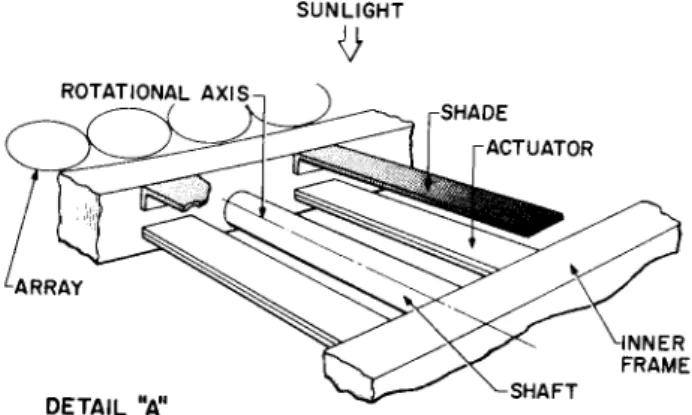
Bi-Metallic Strip Orientation Trim System General Description In the bimetallic strip orientation system, two pairs of par- tially shaded bimetal strips are located on opposite sides of each gimbal axis as shown In Figs, k, 5j and 6. These strips are cantilevered to the sub-array panel and inner gimbal frame and are semi-rigidly attached to the supporting frames. When the subarray panel is properly oriented toward the sun, each set of bimetal strips will recieve an equal amount of incident solar radiation, and moments transmitted to the panel will can- cel each other. If the optical axis of the subarray apnel is misoriented from the axis to the solar disc, one set of bi- metallic strips will intercept more solar radiation than the
corresponding set, and a corrective moment or moments will re- sult from the differential deflections of the strips. This corrective moment will cause the subarray panel to align itself toward the sun by rotational movement about the gimbal axes.
In this manner, each subarray panel can be oriented towards the sun within l/2° from any point within a 6° solid angle.
The design theory, stability analyses, and response charac- teristics have been documented and are available.
Tension Wire Orientation Trim System General Description In the tension wire system, corrective motion is supplied Ъу thermal expansion or contraction of a pair of parallel wires.
Fig"are 7 is an isometric drawing of this system and, as shown in the figure, parallel wires are arranged on either side of the gimbal axis pivot. At the support frame, the wires are attached to a spring loaded flexure coupling, and the other end of the wires are attached to a simple linkage which is joined to the inner frame or subarray panel. A single arm shade par- allel to the tension wires is also attached to the inner frame or subarray panel.
The sun shade is positioned such that, when the subarray pan- el is correctly oriented, a shadow is cast between the two wires.
As they are both exposed to sunlight, they are at the same temperature. When the subarray panel becomes misoriented, the sun shade casts a shadow on one of the wires, and as the tem- perature of the shaded wire decreases, the length of the wire also decreases. This change in length, acting through the linkage to provide rotational motion about the gimbal axis, re- orients the panel toward the sun.
A flexure coupling at the outer frame maintains a constant tension in the wires and allows for gross thermal changes of the subarray panel as it enters or leaves dark operation. This system of orientation trim provides very precise alignment to- wards the sun, since all corrections are brought about by changes in length of the wires relative to each other.
Conclusion
With the advent of communication and navigation satellites requiring mission capabilities of a year or greater, there exists a need for a continuous power supply system to meet
this long life criteria. A fully developed solar-thermoelectric power system, using the high thermal storage capabilities of Lithium Hydride would fill this requirement.
References
-43eal, C. S., "Orientation trim system," Hamilton Standard Div., United Aircraft Corp., EP-611006, Suppl. A (January 16, 1962).
^Lang, R. and Lubin, B. T., "A basic solar thermoelectric power unit," Inst. Aerospace Sci. Preprint 62-1*2 (January 1962).
3Bloom, J. L. and Weddell, J. B., "13 watt isotope-powered thermoelectric generators for space by lunar impact missions,"
ARS Preprint 1332-60 (I960).
^■Loring, S. J., "Solar thermoelectric power supply for transit satellite systems," Hamilton Standard Div., United Aircraft Corp., EP-6IIO66 (October 12, 196l).
-^Shair, R. C , "Electrochemical cells for space power," ARS Preprint 2165-61 (October 1961).
^Howard, P. L., "Wet cell batteries for power," Product Eng., 76 (February 15, 1962).
'Howard, P. L., "The sealed silver-cadmium battery," Inst.
Radio Engrs. (March 22, 19б1).
^Howard, P. L., personal communication.
^Wilson, R. J., Streb, A. J., and Bustard, T. S., "Nuclear auxiliary power unit for lunar exploration," Martin Marietta Corp., Baltimore, Md.
Dushman, S., Vacuum Techniques (John Wiley and Sons Inc., New York, 19^9), p. 61.
■^-Jacob, M., Heat Transfer (John Wiley and Sons Inc., New York, 19k9), VoTTT, p. «3.
Table 1 Properties of lithium hydride (LiHJ
Property Units Value Melting point
Heat of fusion Specific gravity
298°K 673°K
9бО°К (solid) 9бО°К (liquid)
Thermal conductivity at 773°K Compact (powd er)
Crystals
Liquid at 9бО°К а
a Estimated value based on Kardos1 equation for thermal con- ductivity of liquids;
k = cpvL = 0.0105 w/in.°C, where c = specific heat =3799 w/-/sec/lb°C p - density = 0.021 lb/in.3
v = sound velocity in liquid 3«6 x 10 in./sec (assumed on basis of other liquids)
L = distance between molecules= 3-75 x 10"^ (KARDOS* value) This agrees with a very roughly measured value of O.OO8 watt/in.°G
deg. K w/hr/lb
w/in.°C
96O 330
O.78 О.7З O.69 O.58
O.O9I 0.109 0,010
Tahle 2 Heat halance i n u n i t c e l l with thermal energy s t o r a g e 1. Thermal energy storage
a) LiH container is cone 1.75 in- high, "base to apex, hase diameter 2.50 in. with O.UO in. diameter copper rod on axis as radiation collector and thermal conductor.
b) Conical surface area 8Л in.
c) Base surface area 5.3 in.
d) Net volume of container for LiH 2.00 in.3 e) Weight of liquid LiH including 5$ void
and 10$ unmelted solid (density =
0.021 lh/in.3 О.О357 1Ъ f) Heat of fusion thermal energy storage
capacity at 330 w/lh 11.7 w/k/hr g) Eegfd. capacity (item kb) 10.3 w/hr 2. Continuous heat losses
a) Reradiation from collector 0.kO in. dia.
in length; * =0.30 on cylindrical sur-
face, 0.10 on top; temperature = 1000°K 5-6 w b) Radiation from conical surface of con-
tainer to radiation shield € = 0.02 on
surfaces; T = 9б0°К 2.2 w c) Conduction loss in LiH container
support struts 1.0 w d) Radiation from hack of hot junction
radiation collector 0.5 w 3. Thermocouple heat input for 8-in. diameter reflector
a) Projected active reflector area ^2.0 in.
h) Solar constant 0.90 w/in.
Table 2 (Continued)
c) Reflectivity of reflector surface O.85
d) Collector absorptivity O.9O e) Absorbed radiation during sunlight 29.0 w
f) Average heat input during period of 55 min.
sunlight, 35 min. dark 17.7 w g) Continuous heat losses from item 2, this
table 9.3 w h) Continuous heat supplied to thermocouple
hot junctions 8 Л w K. Thermal energy storage requirement
a) Average continuous heat output equals
average input of item 3f 17»7 w b) Thermal energy storage requirement
for 35 min. dark period 10.3 w/-/hr
ТаЪ1е 3 Determination of representative value of temperature drop in LiH and copper at end of melting
Temperature drop in LiH Liquid-solid interface area
(Torus with D = 1.0"; d= 0.30") Wetted container wall area
Representative average conduction area, A Representative conduction path length, L
3.0 in.*
12.7 in.2 5.0 in.2 0.25 in.
Heat flow rate to liquid-solid interface, q 11.2 w Conductivity of liquid LiH, k
Representative temperature drop in LiH Д Т г qL/(kA)
Temperature drop in Cu Total heat flow into copper, g Representative conduction area, A
Representative conduction path length, L Conductivity of Cu, k
Representative temperature drop in Cu A T =qL/(kA)
0.010 w/in.°K
5б°К 23 Л w
0.25 in.2 1.0 in.
9-75 w/in.°K
10°K Tahle h Limiting conditions of thermocouple operation
Temperature of hase of LiH container
Heat input to temper- ature of thermocouple
>K
J^L
Th 5K TcEnd of melting 1010 Start of freezing 960 End of freezing 95^
Start of melting 960
9.25 638 7.8O 573 7.55 563 7.80 573
З63 3^0 337
3to
2.0,
I"
d 1-21 1.6_j
K 1.0 x —
" 0 . 8
0.2
Г' /
PRESEN LIMIT 0
HERMAL STORAGE
L ISOTOPE POWERED THERMOELECTRIC
TLIFE FBATTERIE
SOLAR CELLS a BATTERIES
Ч ч _ LABORATORY LIFE :S 1 LIMIT. OF BATTERIES
^
\ _ SOLAR THERMOELECTRIC WITH BATTERIES , | |
0.3 0.4 0.6 0.8 1.0 2.0
MISSION TIME-YEARS 3.0 4.0 6.0 8.0 10.0
Fig. 1 Specific weight vs mission duration for various continuous power system
_—\,j
Fig. 2 Solar thermoelectric unit cell
COPPER CONDUCTING CONTAINER WALLS CLAD WITH 316 STAINLESS STEEL INSIDE
-8IN.
TYPICAL SUPPORT STRUT
THERMOELECTRIC ELEMENT
HOT JUNCTION RADIATOR
COLLECTOR 3.4 IN.
ELECTRICAL LEAD COPPER BRAIDj— HONEYCOMB CONNECTOR ( SUPPORT PANEL
Fig. 3 Section diagram of unit cell
DETAIL "A' ACTUATORS
INNER FRAME-
Fig. k Bimetallic orientation trim system
SUNLIGHT
ROTATIONAL AXIS-,
SHADE ACTUATOR
DETA.L V ^
Fig. 5 Bimetallic orientation trim system
^TRUE DIRECTION OF SUNLIGHT
SHADE
<L FIXED FRAME
Fig. 6 Bimetallic orientation trim system; general arrangement end view
SUN SHADE
YOKE
LEVER ARRAY
PIVOT AXIS PIVOT MOUNTING
TO MAIN FRAME SHAFT
Fig. 7 Tension wire orientation trim system