SUNFLOWER POWER OONVERSION SYSTEM1 James A« Rudy^
Thompson Ramo Wooldridge Ine·
Cleveland, Ohio
Abstract
A presentation of the Sunflower system concept is devel- oped by tabulation of the primary performance and operational requirements and discussion of the technical implications of these requirements on component design· The similarities and differences between Sunflower and SNAP II are specified and reasons for same are noted·
The Sunflower technical concept is briefly correlated to current state of the art. This correlation, together with similarities in future technological development objectives, illustrates the expected gains in economy and reliability resulting from the close relationship between SNAP II and Sunflower·
Sunflower is a mercury Rankine solar power conversion system being developed by TRW for the NASA· It is a 3 Kw system intended to operate in circular earth orbits for a period of one year·
Introduction
Sunflower is a solar power conversion system being devel- oped by Thompson Ramo Wooldridge Inc· under contract to The National Aeronautics and Space Administration· The contract effort was initiated on June 1, I960 and the currently con- tracted development program is to be completed April 1, 196U·
1) Presented the ARS Space Power System Conference, Santa Monica, California, September 27-30, I960
2) Project Manager, New Devices Laboratory
The objective of this paper is to describe the proposed Sunflower System, to define the bases on which it has been conceived and to establish the relationship of the Sunflower system requirements with the state of the art of today1 s power conversion system development.
System Description
The Sunflower system is a Mercury Rankine power conver- sion system with concentrated solar energy employed as the heat source and cycle heat rejection accomplished by direct radiation to the space environment. A pictorial view of the system is shown in Figure 1· The major components of the system include the déployable paraboloidal mirror which fo- cuses solar energy into the cavity receiver. The configura- tion of the solar collector in the launch condition is shown in the insert to Figure 1. The cavity receiver is surrounded by the boiling tubes of the Rankine system. These tubes are imbeded in lithium hydride to provide the thermal energy storage required for sun-shade operation. The vapor generated in the boiler then passes through the turbine which drives the turbogenerator unit. The spent vapor then passes to the direct radiating finned tube condenser, wherein waste energy is rejected to space and the mercury vapor is condensed. The condensate passes to the subcooler, wherein sufficient addi- tional energy is rejected to space to cool the condensate an amount sufficient to prevent cavitation of the condensate pump. The condensate pump accepts liquid mercury from the subcooler and provides pressurized mercury for the boiler, thus completing the working fluid loop. Pump output flow is also directed through a secondary loop which provides lubri- cation for the bearings of the turbogenerator unit. Auxil- iary equipment required for operation of the system is
located in the auxiliary section of the assembled package and include the following:
1. Rotational Speed Control - The rotational speed con- trol compares the frequency output of the turbogen- erator with a self generated reference frequency and generates an error signal· This frequency error sig- nal is amplified and employed to vary the conductance of a parasitic load connected in parallel with the useful load of the satellite vehicle. Thus the ro- tational speed control provides an adjustment of total power output of a turbogenerator unit to main- tain frequency control to the required specifica- tions. This provides a trim on the actual power output of the system at its rated useful load of
three kilowatts and permits a reduction of useful load down to essentially zero without loss of rota- tional speed stability or frequency control*
2· Startup Auxiliaries - Auxiliaries are provided to permit the accomplishment of orbital startup of the system· These include a sequencing control to sequence the operations of collector deployment, condenser preheat, mercury inventory charging, and the startup equipment·
System Specifications
The fundamental performance and mission requirements of the Sunflower system may be listed:
Power - 3 kilowatts
Voltage - 110 volts, line to neutral, two phase, alter- nating current
Frequency - 2000 cycles +· 1%
Mission Requirements - Bated useful power output contin- uously for durations of one year at circular earth orbits of 300 nautical miles to 20,000 nautical miles altitude· The variation of maximum earth shadow time and orbit percentage suntime with orbital altitude are shown on Figure 2. (J. W· Powell's derivation) Accelerations - Launch accelerations up to 10 g's non-
operating· The system is required to start once the desired orbit is reached· Subsequent operation is re- quired at virtual zero gravity for the bulk of the one year operating duration with brief periods of operation required during accelerations of up to 1 g in any direction·
Design Approach
The primary objective of the Sunflower Program is the development of a power supply system of high reliability meeting the above noted specifications on a timely basis·
This fact has a direct bearing on the technical and program concepts employed in its development·
In the conception of the Sunflower system, significant utilization has been made of the SNAP development programs which have been in progress at Thompson Eamo Wooldridge for the last four years· Primary design and development support is obtained from the SNAP II Program· The basic similarities between the SNAP II and Sunflower Systems are; they both
employ a Hankine Cycle power system utilising mercury as the working fluid, and both provide a useful power output of three kilowatts at similar voltage and frequency· These basic similarities allow the potential of utilization of much of the SNAP II hardware and technology· Primary examples of this utilization are as follows:
1. Turbogenerator - SNAP II turbogenerator is readily usable to the Sunflower system with some modifica- tion· The major modification is the deletion of the requirement to circulate a secondary fluid from the heat source to the mercury boiler as is required in the SNAP II System.
2. Rotational Speed Control - The SNAP II rotational speed control may be readily used in the Sunflower System in that similar turbogenerators are employed and the nominal output frequencies are the same·
3· Zero Gravity Technology - The zero gravity mercury boiling and condensing technology is applicable;
however, detailed designs cannot be common to both systems·
There are some differences between the SNAP II and Sun- flower Systems. The identification and reasons for these differences are briefly outlined below.
The basic difference between the Sunflower and SNAP II Systems lies in the heat source. The SNAP II System employs a heat source which, in the relevant power range, has a weight which is independent of the thermal power supply requirement·
Thus in the SNAP System the influence of system efficiency on system weight is limited to the condenser and, to a lesser extent, the boiler· In the Sunflower System, however, varia- tions in overall cycle efficiency directly affect the weight of the solar collector and the energy storage system, as well as the radiative condenser. Since these components comprise a major share of the system weight, it is found that system weight minimization requires the maximum cycle efficiency obtainable within the heat supply and heat rejection limits of the system concept as developed below·
As was stated earlier in the paper, the heat of fusion of lithium hydride is employed to accomplish energy storage for sun-shade operation· Lithium hydride is chosen for this application because its thermal storage capacity exceeds that of other known materials by a factor of four to five. This
fact coupled with 'the favorable temperature at which LiH melts, namely 1256°F, make LiH a desirable choice for this purpose. Thus the upper cycle temperature is fixed at some- thing less than 1256°F. On the lower cycle temperature end, cycle efficiency optimization shows that minimum system weight will occur at a rejection temperature below that ob- tainable with a reasonable condenser pressure· For this reason the heat rejection temperature is selected at the lowest corresponding condensing pressure to which the system can be designed to provide the required net positive suction head at the condensate pump inlet· The heat rejection condi- tions selected in this fashion are:
Condensing Temperature 600°F Condensing Pressure 6 PSIA Subcooled Temperature UOO°F
(Corresponding subcooled mercury vapor pressure is 0.33 PSIA)
Thus the upper and lower cycle temperatures are deter- mined by the melting point of lithium hydride and the net positive suction heat limitations on the condensate pump re- spectively·
The remaining basic Eankine Cycle variable is the boil- ing pressure· With respect to boiling pressure, maximum cycle efficiency for a ftankine Cycle operating between fixed upper temperature and lower pressure limits is obtained at saturated vapor at turbine inlet· This would indicate that the desirable boiling temperature and pressure would be 1250°F and 650 PSIA respectively. However, opposing this advantage is the effect of relatively high inlet pressure upon turbine performance for the relatively fixed configura- tion of the Sunflower system· Increasing turbine inlet pressure eventually results in lower overall system perform- ance due to the predominance of lower turbine efficiency over cycle efficiency· This is shown by the plot of power into working fluid versus turbine inlet pressure at the fixed upper temperature and lower pressure cycle conditions presen- ted on Figure 3· This figure shows that power into the work- ing fluid is optimized at a turbine inlet pressure of 280 PSIAj however, with the realization of the fact that the con- densate pump developed for SNAP II is limited to supply
pressures of approximately 320 PSIA, and with consideration of the boiler pressure drop, the decision was made to reduce boiling temperature by 200°F to a value of 1050°F. Thus a turbine inlet pressure of 21*0 PSIA is selected.
The boiler outlet pressure of SNAP II is 105 PSIA· Thus Sunflower employs a turbine pressure ratio of somewhat more txhan twice that which is used in the SNAP II System· This increased pressure ratio plus the general increased sensitiv- ity of system weight to system thermal efficiency have dic- tated the selection of a three stage turbine for the Sunflower system as compared with the two stage system employed for SNAP II· This change constitutes the second modification which is required in the SNAP II turbogenerator unit·
The degree of improvement in cycle efficiency effected by the increase in boiling pressure and elimination of the NaK circulating pump power requirement may be quantified by com- paring the boiler heat input requirements of the SN&P II and Sunflower Systems. These values are k9 kilowatts and 33 kilo- watts respectively·
A tabulation of the weight of the major elements of the Sunflower System as defined above follows;
Solar Collector 186 pounds Boiler/Heat Storage 260 pounds Turbogenerator 30 pounds Condenser 62 pounds Mercury Inventory 15 pounds Rotational Speed Control 15 pounds Startup Auxiliaries 65 pounds Structure and Miscellaneous Plumbing 67 pounds Total 700 pounds
Major System Components
The following paragraph presents a brief descriptive discussion of each of the major components of the Sunflower System·
Solar Collector - As was noted above the solar collector consists of an annular section of a single paraboloidal mirror formed of forty-eight rigid segments· Each segment is hinged at its attachment to a mounting rig located at the base of the system assembly· To illustrate the deployment concept employed Figure U presents sequence photographs of the deployment of the ten foot prototype model which has been fabricated at Thompson Eamo Wooldridge and tested for optical quality in the laboratory· The petals are made of aluminum honeycomb material joined by an epoxy adhesive. The prototype model mirror shown in Figure U has been fabricated of stock thick- ness and honeycomb density characteristic of prototype space
system· The petals have been subjected to deployment and vibration testing as Kell as optical testing· The results of
this evaluation program have been gratifying and both weight and performance estimates for the solar collector employed in the Sunflower System have been directly extrapolated from values achieved on this model· The optical description of the collector employed includes the following parameters:
Collector Outer Diameter - 32·2 feet Collector Inner Diameter - 9.6 feet Focal Length - 17 feet
Aperture Angle - 53°
Cavity Aperture Size - 1·2 feet Concentration Ratio - 600
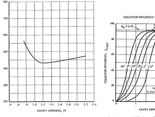
These dimensions have been selected in accordance with a col- lector efficiency and receiver retention efficiency optimi- zation to select the minimum collector-boiler/heat storage weight versus aperture opening as shown on Figure 5· Also con- sidered is the comparative orientation sensitivity as shown on the plot of overall collector efficiency versus cavity open- ing for varying tracking error in Figure 6·
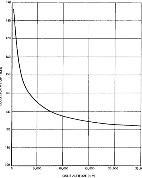
ÜS was implied in the system specification requirements, the collector size is sufficient to power the system at the most adverse sun-shade conditions encountered in circular earth orbits between 300 nautical miles and 20,000 nautical miles altitude· The collector size design point is the 300 nautical mile mission at which orbit the satellite vehicle may be in the sun as little as 62·5% of the time· Excess solar collector area is provided at any orbit with a higher percentage sun time· For any orbit other than orbits near the ecliptic plane, there is a possibility for essentially continuous sun time· Thus, a requirement exists to provide a means of protecting the receiver against over temperature con- ditions· For this reason a collector of excessive size may be utilized; thus the system may be used without modification for altitudes in excess of 300 nautical miles with the large collector sized to the 300 nautical mile orbit· However, if weight were to become critical for any specific orbital alti- tude above 300 nautical miles, the system may be modified by simple reduction of the collector diameter resulting in po- tential weight savings as indicated in Figure 7· This figure is a plot of required solar collector weight versus orbital altitude·
Boiler/Heat Storage Component - A schematic diagram of the boiler/heat storage component is shown in Figure 8· The
major performance requirements of the boiler/heat storage com- ponent are to accept and retain energy concentrated by the solar collector and to ultimately deliver the maximum amount of such energy to the working fluid in the boiler· The heat storage capcity of the boiler/heat storage component is es- tablished by the longest shade time encountered in the re- quired orbital missions· This occurs at the maximum orbital altitude of 20,000 nautical miles at which time, as shown in Figure 2j the shade time can be as great as seventy minutes·
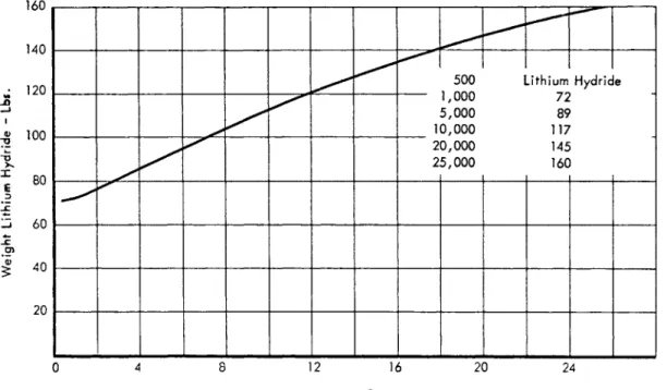
The weight of this component shares with the solar col- lector a dependence on orbital altitude, AS altitude increas- es the weight of LiH required to store thermal energy varies as shown in Figure ?.
To show the possibility of system weight savings obtain- able if the design is to be tailored to a specific altitude, the combined influence of solar collector and LiH weight vari- ation with orbital altitude is shown on Figure 10, which plots total system weight versus orbital altitude·
Turbogenerator - As implied above the Sunflower turbogen- erator component is a modification of the SNAP II turbogener- ator. No component development is anticipated in excess of that which has been and continues to be conducted under the SNAP II Program. The major elements of the turbogenerator package are the three stage impulse turbine, permanent magnet alternator, the jet-centrifugal condensate pump, and the sup- porting shaft and mercury lubricated journal and thrust bear- ings. The package is hermetically sealed to eliminate mercury leakage. The basic design in both the SNAP I and SNAP II configurations has demonstrated the capability for reliable long term continuous operation.
Condenser - A plane surface finned tube radiator is em- ployed as the Sunflower condenser. The size of the radiating surface as well as design fin efficiency are optimized within the limits of available packaging volume· The specific radi- ator configuration shown on Figure 1 is significantly influ- enced by consideration of orbital start coupled with subse- quent operation in accelerations of up to 1 g in any direction.
The latter requirement restricts the location of the comple- tion of condensation and entire subcooling of the condensate to be physically close to the condensate pump inlet. This permits acceleration of the vehicle in any direction without significant influence on pump inlet pressure. This is accomp- lished by performing completion of condensation and subcool- ing in a compact heat exchanger located close to the pump inlet.
258
Condensate droplets formed in the radiative condenser are carried to the compact heat exchanger station by the vapor velocity· Data has been obtained to correlate droplet size and vapor velocity· By proper application of design tech- niques, condensation and transport is accomplished in a manner which results in small condenser pressure drop and virtual independence from the effects of vehicle accelerations in the range of 1 g·
Design execution of this condenser-subcooler concept in- volves a rather straightforward application of the analytical and experimental studies of zero gravity phenomenon derived in the past several years at Thompson ftamo Wooldridge and in conjunction with WADD in the area of actual zero gravity testing·
Conclusions
The Sunflower System concept and development program are solidly based on state of the art advances accomplished by Thompson Eamo Wooldridge in the SNAP Programs· The system concept assures maximum continuing benefits in reliability and performance development from the concurrent SNAP II Program·
References
No direct references relevant to the above paper have been published· The material presented herein is largely the result of TRW's Sunflower proposal effort and the supporting documentation exists only as informal internal company memoranda.
F ië« 1 The Sunflower Solar Power System
260
100
80
O
LU ^ >-
5
in z UJ U .6 .4i
60 iLU ^ LU a < is* 40
30 20 \-r Percentage
'sun
Tshade
12 16 20
ALTITUDE x 10" 3-N. MILES 24 28 32
Pig. 2 Variation of Percentage Sun Time with Circular Orbit altitude
fO
O 3 —ι u.
o z o o z
42
40
38
36 34
32
30
23
26 24 22
*■ j I I >
n
?
CO -<
CO —I m en
100 200 300 350
TURBINE INLET PRESSURE, PSIA
Fig» 3 Power into Working Fluid - Turbine Inlet Pressure
im
co >
n
o
Co -<
CO CO
700
600 !
500
400
300
200
.4 .6 .8 1.0 1.2 1.4 1.6 1.8 2.0 2.2 2.4 CAVITY OPENING, FT
Fig. 5 Optimization Eesults for Collector, Boiler/Heat Storage System
100
ΰ
δ
z
80
60
§ 40
o u 20
COLLECTOR EFFICIENCY VERSUS CAVITY OPENING
1 *N_
<*-
«0.92 J 0
.5°.75°1.0°1.5°
) / /
\ I
/\k
/ /h
2.0°
.5
JZ J
20 ( = ATTITÜDE MISORIENTÂTION 1 H. Coll.'" COLLEaOR EFFICIENCY |
0 1 2 3
CAVITY OPENING <f, FT
Fig. 6 Collector Efficiency Versas Cavity Opening
— and Orientation Error
5,000 10,000 15,000 20,000 ORBIT ALTITUDE (NM)
25,000
Fig. 7 Collector Weicht Versus Orbit Altitude
E POWER SYSTEMS
S ä
266
ro ON - 4
140
*;
]2°
x 100
80
J 60
40
20
500 1 -ithium Hydride 1 ,UUU / 1
5,000 89 10,000 117 20,000
25,000 145 16C
4 8 12 16 20 24 Orbital Altitude x 1 0 "3 - Nautical Miles
Fig. 9 Variation in LiH Weight requirement with
CO
>
n O
CO -<
CO CO
03
E
2 500
-300 ■ H B ^ ^ H H _ «
8 12 16 Orbital Altitude x I 0 *3 - Nalutical Miles
20 24
Fig. 10 Variation in Total System Weight with Orbital Altitude
>
n m
o
CO -<
C O — I
m
CO