Lithium niobate and lithium tantalate based scalable terahertz pulse sources in reflection geometry
G
ERGÖ OK
RIZSÁN,
1,2,*Z
OLTÁNT
IBAI,
1J
ÁNOSH
EBLING,
1,2,3L
ÁSZLÓP
ÁLFALVI,
1G
ÁBORA
LMÁSI,
1 ANDG
YÖRGYT
ÓTH11Institute of Physics, University of Pécs, Hungary
2Szentágothai Research Centre, University of Pécs, Hungary
3MTA-PTE High-Field Terahertz Research Group, Pécs, Hungary
*krizsan@fizika.ttk.pte.hu
Abstract: A new type of THz source, working in reflection geometry, is proposed, where the pulse-front-tilt is introduced by a periodically micro-structured metal profile. For optical coupling, high refractive index nanocomposite fluid is used between the nonlinear optical material and the structured metal surface. Numerical simulations predict∼87 and∼85% optimized diffraction efficiencies for lithium niobate and lithium tantalate at 1030 and 800 nm pump wavelengths. The largest diffraction efficiencies can be achieved for a larger refractive index of the nanocomposite fluid than the index of the nonlinear material, for both cases. THz generation efficiencies of∼3 and∼1% are predicted for lithium niobate and lithium tantalate, respectively.
© 2020 Optical Society of America under the terms of theOSA Open Access Publishing Agreement
1. Introduction
Among several applications, acceleration of electrons [1,2] and protons [3,4] is a potential use of THz pulses with extremely high pulse energy and peak electric field strength in the low-frequency part of the THz spectrum. Optical rectification of near-IR ultrashort laser pulses in nonlinear materials can be appropriate for the efficient generation of such THz pulses. Disadvantageously, for several excellent nonlinear optical materials, the significant difference between the near-IR and THz refractive indices hinders the fulfillment of the necessary velocity matching by standard ways. The tilted-pulse-front pumping (TPFP) [5] became a popular technique to overcome this problem. In the TPFP geometry, the velocity matching reads as:
vp,grcos(γ)=vTHz,ph, (1)
wherevp,gris the group velocity of the pump pulse,vTHz,phis the phase velocity of the THz pulse, andγis the pulse-front-tilt (PFT) angle.
In the past two-decade lithium niobate (LN) became a compelling material in TPFP sources.
Several applications, such as particle acceleration and manipulation, require extremely high THz peak electric field strength, which makes necessary the focusing of the THz beam. So, besides upscaling the pulse energy, good focusability is also essential, which requires uniform THz pulse shape along the beam cross-section. The conventional LN THz sources, containing optical grating and imaging elements, have substantial limitations. These are the following: (i) Limited interaction length due to angular dispersion. (ii) Prism shape of the LN crystal with a large (γ≈63◦) wedge angle. (iii) Imaging errors. Energy scalability is limited by (i-iii), while the availability of uniform THz beam is limited mainly by (ii) and (iii) [6,7]. In the past few years, extensive effort has been made to investigate and reduce these limitations as much as possible [6–13].
In 2017, a plane-parallel nonlinear echelon slab (NLES) was suggested [14], which solves (ii) and significantly reduces (i) and (iii) allowing the extension of the useful pump diameter [15].
#405748 https://doi.org/10.1364/OE.405748
Journal © 2020 Received 18 Aug 2020; revised 17 Sep 2020; accepted 18 Sep 2020; published 28 Oct 2020
Working principle and single-cycle THz waveform generation possibility have been demonstrated for such setup [16].
A more compact setup can be obtained by omitting imaging optics [17]. This wedged NLES setup solves (iii) and significantly reduces (i), and (ii), only a small (<10◦) wedge angle must be used. In this case, a homogeneous THz beam is predicted for as large as∼2.5 cm pump beam diameter.
An even more compact THz pulse generation source has been proposed, which is absent of external optical grating as well as of imaging element. This source (reflective nonlinear slab, RNLS) contains only one single element: a plane parallel nonlinear material having a periodic structure created in its back surface [18]. RNLS eliminates (ii) and (iii), so in this case, there is no limitation for the pump spot size. However, manufacturing the necessary structure on the LN surface is challenging and expensive.
In the present paper, we recommend a new concept that has all the advantages of the earlier presented RNLS setup. However, the tilted pulse front is created by diffraction from an external surface reflector (ESR) in order to avoid the manufacturing of the expensive and brittle LN crystal. Advantageously, the micromachining of the less expensive and more ductile metals can result in even better surface roughness and form accuracy compared to LN [19,20]. Furthermore, using ESR, the LN crystal can be reused under modified experimental circumstances as well. By microstructuring metals, molds can be produced, making possible the cheap serial production of ESRs.
The setup is investigated at 800 nm and 1030 nm central pump wavelengths. Since for 800 nm pump wavelength, the disadvantageous three-photon absorption appears in LN, lithium tantalate (LT), which has similar linear and nonlinear optical properties as LN but has a larger band gap is also considered [21,22].
2. RNLS with ESR
The concept introduced in Ref. [18] proposes THz generation by pump beams diffracted in the
±mthorders from the periodically micro-structured back surface of the nonlinear material (NM), as shown in Fig.1(a). The periodic structure introduces an angular dispersion of the pump beam and creates (on a large scale) a tilted-pulse-front, which is parallel with the NM surfaces (see the red horizontal band in Figs.1(a) and (b)) implementing a noncollinear velocity matched configuration according to Eq. (1). The generated THz beam and the pump pulse leave the crystal in the same direction with some time difference (the pump beam first suffers a total internal reflection on the exit surface of the crystal and backpropagates towards the microstructured surface of the crystal. The pump beam can exit from the crystal only after this second diffraction).
Separation of the generated THz pulse and the reflected pump pulse can be achieved by using a dichroic beam splitter e.g. an indium-tin-oxide coated glass substrate [23,24].
Naturally, to fulfill the velocity matching condition (Eq. (1)), the necessary spatial period dof the microstructure has to be proportional to the diffraction order m . By increasing m the structure gets to be more rough, for large m values it starts to behave rather as a reflector.
However, creating this structure with optical surface quality and the d falling into the micrometer or a few-micrometer regime is challenging since dielectric materials are brittle. So, here we suggest an alternative (see Fig.1(b)) of the original RNLS setup, the reflective nonlinear slab with external structured reflector (RNLS-ESR). In this setup, contrary to the RNLS, the backside of the NM is unstructured (flat), and an external metal grating facing to the back surface of the NM slab is applied in order to create the±mthdiffraction orders of the pump beam. Gold coating evaporated on a copper or aluminum structured substrate can ensure high reflectance because of the low absorption of gold in the near-IR range [25]. For successful optical coupling, a high refractive index liquid (HRIL) is used between the NM and the ESR.
Fig. 1.Schematic views of the RNLS and RNLS-ESR setups. The pump beam enters the NM perpendicular to its surface. It is diffracted into the±mthorders of the periodic structure situated on the backside on NM, generating the tilted-pulse front (red band parallel with the NM surfaces) of the pump pulse. The THz is generated perpendicular to the tilted-pulse front and leaves the NM perpendicular to the NM surface. a) Simple RNLS setup, where the periodic structure is created on the back surface of the NM b) RNLS-ESR, where the periodic structure is created on a metallic surface (ESR). For optical coupling, an HRIL is used between NM and ESR.
3. Diffraction efficiency of the ESR
The diffraction efficiency (DE) (the Fresnel-losses at the HRIL - NM interface, and the absorption loss of the gold was taken into account) as a function of the HRIL’s refractive index (nHRIL) was determined by COMSOL simulations for a few diffraction orders. The results are shown in Fig.2 for LN (a and b) and LT (c and d) NMs, respectively. In all cases, the DEs increases with the diffraction order over the investigated HRIL refraction index range. Increasing the diffraction order, thenHRIL value corresponding to the DE maxima first decreases, then asymptotically approaches a value (indicated by dashed lines), which is significantly larger than the LN or LT index of refraction of the NM (indicated by the dotted line). Please notice that the Fresnel losses at the HRIL–NM interface disappears for thenHRIL=nNMindex-matched case, and this is equivalent to the case of the original simple RNLS (with integrated, non-external structured reflector).
At both wavelengths, the maximally available DEs are∼87% and∼85% for LN and LT, respectively (Fig.2). According to Fig.2for both NMs and wavelengths, the maximal DE predicted for the RNLS-ESR setup is larger than the DE predicted for the simple RNLS (vertical dotted lines). This DE enhancement is more remarkable for the LT than for the LN at all examined diffraction orders. At m=30, the DE enhancement is 2−3% for LN, while it is∼20% for LT.
Both this DE enhancement and the situation of the DE maxima at a larger index of refraction value than the index-matched case can be explained by simple geometrical reasoning as follows:
Velocity matched THz generation requires the diffraction angle to be equal with theγvelocity matching angle. In the case of the RNLS and RNLS-ESR setup, where the pump beam has a normal incidence to the periodic structure, the blazing condition is fulfilled if the inclination angle of the symmetric sawtooth profile isγ/2. However, for materials withγ>60◦requirement, a part of the diffracted pump beam is blocked (reflected in unwanted direction) by the neighboring grid due to simple geometrical reason, resulting in decreased DE. This effect just appears for LN (γ≈63◦), but it is more remarkable for LT withγ≈69◦. For the RNLS-ESR setup, it is possible to eliminate this negative effect by usingγL ≤60◦diffraction angle in the HRIL region (see Fig.1(b)) and increasing theγdiffraction angle in the NM by using HRIL with a larger index of refraction than the refractive index of the NM. The Fresnel loss at the HRIL-NM boundary is also a responsible factor in the DE. This loss is, however zero for thenHRIL=nNMcase (indicated by the dotted vertical lines in Fig.2). IncreasingnHRILthe Fresnel loss develops. However, due to the small difference between the refractive indices of the materials, this effect is significantly
Fig. 2.Diffraction efficiencies for diffraction orders from 1 to 30 in case of LN (a,b) and LT (c,d)) RNLS-ESR for (a,c) 800 nm and (b,d) 1030 nm wavelengths. The dotted vertical lines represent thenHRIL=nNMindex-matched case and the dashed one represents theγL=60◦ geometry.
smaller than the above mentioned geometrical loss, which dominantly determines the DE for large m values and shifts the maximum practically to the dashed vertical lines in Fig.2.
Because of the above discussed DE enhancement, the RNLS-ESR, shown in Fig. 1(b) is especially promising when NM with a large necessary pulse front tilt angle (for example, LT) is applied.
4. Nanocomposite fluid as HRIL
To achieve the highest DE, as discussed above, the angle of diffraction (and the PFT) should be 60◦in the HRIL. For this, the refractive index of the HRIL has to be higher than that of the NM.
The necessary refractive index of the HRIL is determined by the simple equation:
nNMsin(γ)=nHRILsin(γL). (2) This means that applying LN or LT as NM, the refractive index of the HRIL should be around 2.2-2.3. To the best of our knowledge, there is no liquid with such a high refractive index.
Therefore, we suggest using nanocomposite fluid, where nanopowder is dispersed in liquid in order to achieve the appropriately high refractive index. The index of refraction of the nanocomposite fluid can be calculated according to the Lorentz-Lorenz model [26] by using the following equation:
n2HRIL−1
n2HRIL+2 = Vnano
V ·n2nano−1 n2nano+2+
1−Vnano V
·
n2liquid−1
n2liquid+2, (3)
where,Vnano/V is the volume ratio of the nanopowder in the liquid, andnliquid,nnanoare the liquid and the nanopowder refractive indices, respectively.
We consider carbon disulfide (CS2) as a solvent because it is a stable liquid for optical applications and has a relatively high refractive index [27]. The nanopowder should have small absorption and high refractive index at the pump wavelength (λ0) and (in order to minimize light scattering) its size should be smaller than 0.1λ0/nHRIL. Nowadays, such nanopowders are commercially available with spherical shape [28]. In Table1we gave the refractive index values for the selected materials at 800 and 1030 nm wavelengths and a few possible mixtures for the different applications. Since the optical properties (such as the refractive index) of the nanoparticles are size-dependent [29–31], and there is an uncertainty in the size of the nanoparticles, theVnano/Vratios calculated from Eq. (3) can only serve as a starting point for the preparation of the mixtures. Before usage, all mixtures should be measured and characterized individually.
Table 1. Refractive index of the selected materials and mixtures for the different NMs
NM λ0(nm) nHRIL Liquid nliquid nanopowder nnano Vnano/V(%)
LN 800 2.23 CS2 1.61 GaP 3.18 55
LT 800 2.32 CS2 1.61 GaP 3.18 61
LN 1030 2.23 CS2 1.60 GaP 3.11 57
LT 1030 2.31 CS2 1.60 GaP 3.11 62
5. THz generation efficiencies for RNLS-ESR
In order to get information on the optical-to-THz generation efficiency, numerical simulations were performed based on the model described in Ref. [18]. The model takes into account the pump pulse length variation during the propagation due to the material and angular dispersion, the Fresnel losses of the pump and the THz pulse on the interfaces of the structure and the surface of the crystal, as well as the THz absorption of the crystal. The depletion of the pump pulse and the effects due to the feedback of the THz pulse to the pump pulse were not considered, therefore our calculations can be considered reliable only up to approximately 2% efficeincy [6].
LN and LT have similar effective nonlinear optical coefficient for THz generation [32], but the THz absorption coefficient is more significant for LT [21] than for LN [33]. However, at 800 nm pump wavelength for typical pump intensities, the free-carrier-absorption introduced by the three-photon-absorption in LN [34] is one order of magnitude higher than the THz absorption of LT [21]. Therefore, at 800 nm, pump wavelength LT is the better choice, while at 1030 nm, LN is preferred. Similarly, as in Ref. [18] a square root dependence of the damage threshold on the pump duration was supposed, and accordingly, the peak pump intensity for the different pump pulse duration was given by
I0=I0∗ s
100fs
τ0 , (4)
whereτ0is the pump pulse duration andI∗0is the peak pump intensity at 100 fs with values of I0∗=100GW/cm2andI0∗=200GW/cm2for LN and LT, respectively [35,36].
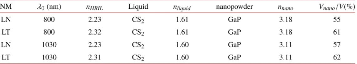
The simulation results are plotted in Fig.3for LN (a) and LT (b). As it is seen, the useful crystal length is substantially shorter for LT, because of its higher THz absorption coefficient.
Despite the two times higher pump intensity, at room temperature, the maximum THz generation efficiency at the investigated pulse duration range is significantly smaller in LT (0.71%) than in LN (3.75%). We would like to note that high energy laser systems typically work at 100 fs and 200 fs pulse duration at 800 nm and 1030 nm central wavelengths, and for these, the maximum predicted conversion efficiency is 0.3% and 2.2% for LT and LN, respectively.
Fig. 3.THz generation efficiency at room temperature in a) LN at a pump wavelength of 1030 nm and b) LT at a pump wavelength of 800 nm keeping the pump intensity about two times below the damage threshold for varying pulse duration and both crystals (see text for details).
Using CS2as a solvent in the nanocomposite fluid enables cryogenic cooling to its freezing point, which is 163 K. In the absence of cryogenic THz absorption coefficient literature value for LT, no simulations were made for the low-temperature cases. We expect that LT THz absorption will decrease similarly as LN [37]; therefore, the THz-generation efficiency could be higher than 1% in the case of LT at low temperature.
6. Conclusion
We introduced an imaging free, plane-parallel, easy-to-manufacture THz pulse source, which is especially advantageous for those NMs where the necessary PFT is greater than 60◦. This setup is a further developed version of the RNLS and, like that one, allows the upscaling of the THz pulse energy without principal limitations. A periodically micro-structured external metal profile introduces the PFT for velocity matching. For optical coupling between the NM and the metal surface, an HRIL is used. We gave examples for making nanocomposite fluids with the appropriate refractive index to be used for HRIL. Numerical simulations predict that outstanding diffraction efficiencies can be achieved for LN (∼87%) and LT (∼85%) NMs for 800 nm and 1030 nm wavelengths. Numerical simulations were also carried out to show the achievable THz generation efficiency by the most common high-energy lasers. Simulations predict a few percent conversion efficiency for LN at 1030 nm pump wavelength. At 800 nm pump wavelength LT is recommended for THz generation since free-carrier-absorption introduced by the three-photon-absorption can be excluded. In this case, the maximal conversion efficiency is somewhat below 1% on the examined parameter range. With cryogenic cooling, we expect THz generation with significantly larger than 1% efficiency.
We performed simulations for metallic ESR, which is technically probably the simplest solution.
However, more cost-effective production of the ESR could be the creation of a master periodic structure by micromachining of metal, then creating replicas from glass by molding, finally, creation of dielectric mirror structure on the surface of the glass replicas. Such replica ESR would have similar diffraction efficiency than metallic ESR but would allow using of larger pump intensities due to its larger damage threshold.
Funding
Nemzeti Kutatási Fejlesztési és Innovációs Hivatal (125808, 129134, 2018-1.2.1-NKP-2018- 00010); European Social Fund (EFOP-3.6.1-16-2016-00004, EFOP-3.6.2-16-2017-00005);
Magyar Tudományos Akadémia (János Bolyai Research Scholarship (Gy. T.)).
Acknowledgement
György Tóth would like to thank the support of the János Bolyai Research Scholarship of the Hungarian Academy of Science.
Disclosures
The authors declare no conflicts of interest.
References
1. E. A. Nanni, W. R. Huang, K.-H. Hong, K. Ravi, A. Fallahi, G. Moriena, R. J. D. Miller, and F. X. Kärtner,
“Terahertz-driven linear electron acceleration,”Nat. Commun.6(1), 8486 (2015).
2. D.-F. Zhang, A. Fallahi, M. Hemmer, X.-J. Wu, M. Fakhari, Y. Hua, H. Cankaya, A.-L. Calendron, L. E. Zapata, N.
H. Matlis, and F. X. Kärtner, “Terahertz-driven linear electron acceleration,”Nat. Photonics12(6), 336–342 (2018).
3. L. Pálfalvi, J. A. Fülöp, G. Tóth, and J. Hebling, “Evanescent-wave proton post accelerator driven by intense thz pulse,”Phys. Rev. ST Accel. Beams17(3), 031301 (2014).
4. A. Sharma, Z. Tibai, and J. Hebling, “Intense terahertz laser-driven proton acceleration in plasmas,”Phys. Plasmas 23(6), 063111 (2016).
5. J. Hebling, G. Almási, I. Kozma, and J. Kuhl, “Velocity matching by pulse front tilting for large-area thz-pulse generation,”Opt. Express10(21), 1161–1166 (2002).
6. K. Ravi, W. R. Huang, S. Carbajo, X. Wu, and F. X. Kärtner, “Limitations to thz generation by optical rectification using tilted pulse fronts,”Opt. Express22(17), 20239–20251 (2014).
7. J. A. Fülöp, L. Pálfalvi, G. Almási, and J. Hebling, “Design of high-energy terahertz sources based on optical rectification,”Opt. Express18(12), 12311–12327 (2010).
8. L. Pálfalvi, Z. Ollmann, L. Tokodi, and J. Hebling, “Hybrid tilted-pulse-front excitation scheme for efficient generation of high-energy terahertz pulses,”Opt. Express24(8), 8156–8169 (2016).
9. B. K. Ofori-Okai, P. Sivarajah, W. R. Huang, and K. A. Nelson, “Thz generation using a reflective stair-step echelon,”
Opt. Express24(5), 5057–5068 (2016).
10. L. Tokodi, L. Pálfalvi, and J. Hebling, “Optimization of the tilted-pulse-front terahertz excitation setup containing telescope,”J. Infrared, Millimeter, Terahertz Waves38(1), 22–32 (2017).
11. Y. Avetisyan, A. Makaryan, V. Tadevosyan, and M. Tonouchi, “Design of a multistep phase mask for high-energy terahertz pulse generation by optical rectification,”J. Infrared, Millimeter, Terahertz Waves38(12), 1439–1447 (2017).
12. K. Ravi and F. X. Kärtner, “Analysis of terahertz generation using tilted pulse fronts,”Opt. Express27(3), 3496–3517 (2019).
13. Y. Avetisyan and M. Tonouch, “Nearly single-cycle terahertz pulse generation in aperiodically polad lithium niobate,”
Photonics6(1), 9 (2019).
14. L. Pálfalvi, G. Tóth, L. Tokodi, Z. Márton, J. A. Fülöp, G. Almási, and J. Hebling, “Numerical investigation of a scalable setup for efficient terahertz generation using a segmented tilted-pulse-front excitation,”Opt. Express25(24), 29560–29573 (2017).
15. L. Wang, G. Tóth, J. Hebling, and F. X. Kärtner, “Numerical investigation of a scalable setup for efficient terahertz generation using a segmented tilted-pulse-front excitation,”Laser Photonics Rev.14(7), 2000021 (2020).
16. P. S. Nugraha, G. Krizsán, C. Lombosi, L. Pálfalvi, G. Tóth, G. Almási, J. A. Fülöp, and J. Hebling, “Demonstration of a tilted-pulse-front pumped plane-parallel slab terahertz source,”Opt. Lett.44(4), 1023–1026 (2019).
17. G. Tóth, L. Pálfalvi, J. A. Fülöp, G. Krizsán, N. H. Matlis, G. Almási, and J. Hebling, “Numerical investigation of imaging-free terahertz generation setup using segmented tilted-pulse-front excitation,”Opt. Express27(5), 7762–7775 (2019).
18. G. Tóth, L. Pálfalvi, Z. Tibai, L. Tokodi, J. A. Fülöp, Z. Márton, G. Almási, and J. Hebling, “Single-cycle scalable terahertz pulse source in reflection geometry,”Opt. Express27(21), 30681–30691 (2019).
19. J. McGeough,Micromachining of Engineering Materials(CRC Press, 2001), 1st ed. Chapter 5.
20. M. Roeder, T. Guenther, and A. Zimmermann, “Review on fabrication technologies for optical mold inserts,”
Micromachines10(4), 233 (2019).
21. A. Buzády, M. Unferdorban, G. Tóth, J. Hebling, I. Hajdara, L. Kovács, and L. Pálfalvi, “Refractive index and absorption coefficient of undoped and mg-doped lithium tantalate in the terahertz range,”J. Infrared, Millimeter, Terahertz Waves38(8), 963–971 (2017).
22. L. Tokodi, A. Buzády, J. Hebling, and L. Pálfalvi, “Possibility of high-energy thz generation in litao3,”Appl. Phys. B 122(9), 235 (2016).
23. C.-S. Yang, C.-H. Chang, M.-H. Lin, P. Yu, O. Wada, and C.-L. Pan, “Thz conductivities of indium-tin-oxide nanowhiskers as a graded-refractive-index structure,”Opt. Express20(S4), A441–A451 (2012).
24. C.-S. Yang, C.-M. Chang, P.-H. Chen, P. Yu, and C.-L. Pan, “Broadband terahertz conductivity and optical transmission of indium-tin-oxide (ito) nanomaterials,”Opt. Express21(14), 16670–16682 (2013).
26. M. Trikeriotis, R. Rodriguez, M. F. Zettel, A. Bakandritsos, W. J. Bae, P. A. Zimmerman, C. K. Ober, and E. P.
Giannelis,High refractive index nanoparticle fluids for 193-nm immersion lithography, (SPIE Advanced Lithography, 2002). XXVI. Advences in Resist Materials and Processing Technology, San Jose, California, United States.
27. S. Kedenburg, M. Vieweg, T. Gissibl, and H. Giessen, “Linear refractive index and absorption measurements of nonlinear optical liquids in the visible and near-infrared spectral region,”Opt. Mater. Express2(11), 1588–1611 (2012).
28. O. Mangla and S. Roy, “A study on aberrations in energy band gap of quantum confined gallium arsenide spherical nanoparticles,”Mater. Lett.143, 48–50 (2015).
29. L. B. Scaffardi and J. O. Tocho, “Size dependence of refractive index of gold nanoparticles,”Nanotechnology17(5), 1309–1315 (2006).
30. N. Venkatram, R. Sathyavathi, and D. N. Rao, “Size dependent multiphoton absorption and refraction of cdse nanoparticles,”Opt. Express15(19), 12258–12263 (2007).
31. M. Li and J. C. Li, “Size effects on the band-gap of semiconductor compounds,”Mater. Lett.60(20), 2526–2529 (2006).
32. J. Hebling, A. G. Stepanov, G. Almási, B. Bartal, and J. Kuhl, “Tunable thz pulse generation by optical rectification of ultrashort laser pulses with tilted pulse fronts,”Appl. Phys.78(5), 593–599 (2004).
33. M. Unferdorben, Z. Szaller, I. Hajdara, J. Hebling, and L. Pálfalvi, “Measurement of refractive index and absorption coefficient of congruent and stoichiometric lithium niobate in the terahertz range,”J. Infrared, Millimeter, Terahertz Waves36(12), 1203–1209 (2015).
34. S.-C. Zhong, Z.-H. Zhai, J. Li, L.-G. Zhu, J. Li, K. Meng, Q. Liu, L.-H. Du, J.-H. Zhao, and Z.-R. Li, “Optimization of terahertz generation from linbo3under intense laser excitation with the effect of three-photon absorption,”Opt.
Express23(24), 31313–31323 (2015).
35. H. Chen, X. Chen, Y. Zhang, and Y. Xia, “Ablation induced by single-and multiple-femtosecond laser pulses in lithium niobate,”Laser Phys.17(12), 1378–1381 (2007).
36. Y. Zhang, X. Chen, H. Chen, and Y. Xia, “Surface ablation of lithium tantalate by femtosecond laser,”Appl. Surf.
Sci.253(22), 8874–8878 (2007).
37. A. Buzády, R. Gálos, G. Makkai, X. Wu, G. Tóth, L. Kovács, G. Almási, J. Hebling, and L. Pálfalvi, “Temperature- dependent terahertz time-domain spectroscopy study of mg-doped stoichiometric lithium niobate,”Opt. Mater.
Express10(4), 998–1006 (2020).