MTA-PTE High-Field Terahertz Research Group, 7624 Pécs, Hungary
4Szentágothai Research Centre, University of Pécs, 7624 Pécs, Hungary E-mail:tibai@fizika.ttk.pte.hu
Received 1 December 2017, revised 1 April 2018 Accepted for publication 2 May 2018
Published 5 June 2018 Abstract
The acceleration of single electrons and electron bunches by focused THz pulse pairs has been investigated by numerical simulations. The effect of the choice of the beam waist radius, the carrier-envelope phase, and the propagation direction of the THz pulses on the energy of the accelerated electrons was investigated. The acceleration of electron bunches from rest up to 150 keV was predicted using single-cycle THz pulses with 1 mJ energy and a central frequency in the 0.1 THz to 3.0 THz range. The post-acceleration of electrons by pairs of focused THz pulses has also been proposed.
Keywords: acceleration, electron, THz
(Somefigures may appear in colour only in the online journal) 1. Introduction
Conventional particle accelerators, based on radio-frequency fields, are rather complex and costly devices. In search of simpler and more cost effective solutions, laser-driven com- pact acceleration schemes have been proposed and realized over the past few decades. These setups, utilizing the unprecedentedfield strength of high-power short laser pulses, can become practical alternatives to hundreds-of-meters long conventional particle accelerators. Laser-driven accelerators include laser-plasma accelerators [1, 2], dielectric laser accelerators[3,4], and free-space accelerators[5,6].
With the development of strong-field THz pulse sources over the last decade, a new route has opened up for the efficient acceleration of charged particles. The energy of THz pulses has been increasing by many orders of magnitude, now approaching 1 mJ [7, 8]. Up to 100 MV cm−1 peak electric field has been demonstrated at higher, few tens-of-THz fre- quencies[9]. Efficient THz generation has been achieved by optical rectification in organic crystals [10,11], lithium nio- bate (LN) [12] and semiconductors [13, 14]. THz-driven electron accelerators can offer significant advantages over laser-driven schemes. THz pulses have a wavelength about
two orders of magnitude longer than that of visible or near- infrared pulses. This enables a significant increase in both the interaction length and the number of particles, as compared to laser-driven schemes. Furthermore, due to their picosecond- long period, more precise phase synchronization can be achieved between the particles and an accelerating THzfield.
In recent years, THz-driven electron manipulation [15,16], the electron gun[17], dielectric accelerator[18,19], acceleration in cavity[20], x-ray generation[21,22]and the linear accelerator [23] have been proposed and simulated.
THz-driven electron acceleration in vacuum [24] and in waveguide [25, 26] have been experimentally investigated.
High-energy THz sources can also be suitable for post- acceleration and monochromatization of laser-generated pro- tons [27] and for the direct driving of a low-energy proton source in plasma[28].
In this paper, a numerical investigation of electron acceleration and post-acceleration by counter-propagating focused THz pulses is presented. The injection of electrons is accomplished by ionizing atoms in a gas jet with a short laser pulse and by obstructing part of the THz beams in the initial and post-acceleration stages, respectively. The acceleration scheme is introduced in section2. The acceleration of a single
electron and an electron bunch is described in sections3and 4, respectively. Post-acceleration is briefly discussed in section5, followed by the conclusion in section6.
2. Electron acceleration scheme with focused THz pulses
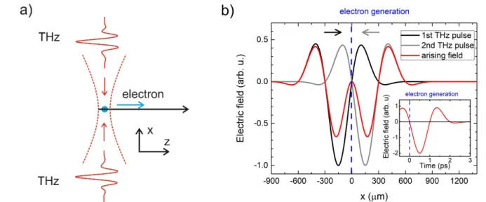
The schematic view of the initial acceleration arrangement (electron gun)is shown infigure1(a). Two counter-propagat- ing single-cycle THz pulses create a transient standing wave.
Ideally, the two THz pulses have the same waveform and the same polarization direction. In this case, the magneticfields of the two THz pulses have opposite directions, thereby mini- mizing magnetic deflection effects on electrons. Electrons are injected by a synchronized short laser pulse which ionizes the atoms in a desired small volume within a gas jet. The generated electrons are then accelerated by the superposition of the electricfields of the two THz pulses(figure1(b)).
The effect of the THz pulses on the electrons is deter- mined by the well-known relativistic Lorentz equation
g = ⋅ + ´
( )
( ( ) ( )) ( )
d mv
dt q E r t, v B r t, , 1 whereγis the relativistic factor,qis the electron charge,
v is the velocity of the electrons,
E is the electricfield strength
and
B is the magnetic induction of the superposed THz pulses. Assuming the polarizations of the THz pulses in thez direction and propagation in the ±x directions, the electric field amplitude is given by:
w
h j
= -
´ - +
+ ⋅
⎛
⎝⎜ ⎞
⎠⎟
⎛
⎝⎜
( )
( ) ( )
( )
– ( ) ) ( ) ( )
E r x E w w x
r w x
kx t k r
R x
x f x t
, exp
sin 2
, , 2
0 0 2
2 2
where r is the radial distance from the propagation axis of the THz beams (x-axis), with the foci located at x=0,
p l
= /
k 2 THz is the wave number,lTHz is the wavelength of the THz pulse,w x( )is the radius at which thefield amplitudes fall to 1/eof their axial values at the planey-zalong the beam, w0is the waist radius,R x( )is the wavefront radius of curvature atx,h( )x is the Gouy phase andj is the phase. A Gaussian profile, f x t( , )=exp(-2 ln 2(x-ct)2/c2 2t ) is taken for the THz pulse, wheret is the FWHM pulse duration.
The values of the parameters assumed in the simulations for the THz pulses are listed in table1. THz pulses with different central frequencies of 0.14 THz, 0.3 THz, 0.7 THz, and 3.0 THz were used in the calculations. The parameters of THz pulses with 0.3 THz central frequency were based on a recent
Figure 1.(a)Initial electron acceleration setup with two single-cycle THz pulses propagating in opposite directions. The blue dot indicates the electron injection position.(b)Thefield of the THz pulses along thex-axis at the optimal birth/arrival time of the electrons.
Table 1.The data of the experimentally generated maximum energy THz pulses at 0.14 THz, 0.7 THz and 3 THz frequencies and numerical investigation of a hybrid-type terahertz pulse source at 0.3 THz frequency used in simulations(*extrapolated values for 1 mJ energy).
Parameter LiNbO3[12] LiNbO3[29] ZnTe[13] DSTMS[8,11]
Mean frequency 0.14 THz 0.3 THz 0.7 THz 3.0 THz
Mean wavelength(lTHz) 2.143 mm 1 mm 0.429 mm 0.1 mm
Electricfield(E0) 1.05–1.74*MV cm−1 0.40–5.21*MV cm−1 1.00–16.9*MV cm−1 48.4–113*MV cm−1 Beam waist(w0) 2.143 mm*–2.4 mm 1 mm*–2.5 mm 0.429 mm*–1 mm 0.1 mm*–0.221 mm
Pulse duration(t) 3.21 ps 1.66 ps 0.85 ps 0.36 ps
Phase(j) 1.54 rad 0 1.54 rad 2.3 rad
Energy 436μJ 337μJ 14μJ 900μJ
J. Phys. B: At. Mol. Opt. Phys.51(2018)134004 Z Tibaiet al
numerical investigation of a hybrid-type LN THz pulse source [29]. At the other frequencies, the simulations were based on published experimental data of THz sources with the highest energies using LN[12], semiconductor ZnTe[13], and organic DSTMS [8, 11] generator crystals. The different reported waveforms, pulse energies, and focused spot sizes were used for most of the calculations. In all cases, a further increase in THz pulse energy can be expected(e.g. by using a large-area LN with uniform crystal length [29] in combination with cryogenic cooling [30], or via infrared-pumped semiconductor contact- grating technology [31]). Therefore, the calculations were also extended to higher, 1 mJ THz pulse energies, assuming dif- fraction-limited focusing to w0=lTHz (the corresponding parameter values are parentheses in table1).
3. Acceleration of a single electron
The energy change of an electron during the acceleration lasts as long as the THz pulse affects the particle; therefore, the
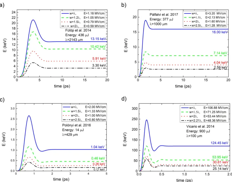
Figure 2.The time evolution of the energy of a single, initially standing electron, accelerated by THz pulse pairs propagating perpendicularly to the electron path. The assumed THz pulse energies were the highest experimentally generated or numerically predicted ones, as given in table1.
Figure 3.Electron energy as a function of the initial phase(j)of the THz pulses. A THz pulse energy of 1 mJ has been assumed in each case.
parameters of the THz pulses determine the efficiency of the acceleration. In this section thefinal energy of a single elec- tron accelerated in the setup shown infigure 1(a)is investi- gated. We optimized the beam waist, the carrier-envelope phase(CEP)and the tilt angle of the propagation direction of the THz pulses(see alsofigure 4(a)below). For the sake of simplicity, the ionization volume has been assumed to be centered at the THz focus. Here, we note that optimizing the position of the ionization volume at the beam waist has led only to a minor off-center shift of about 10μm. The arrival time of the injection laser pulse has been synchronized to the zero-crossing of the THz field preceding the dominant half cycle(figure1(b))[23].
3.1. THz beam waist
In order to reduce the decelerating effect of the positive part of the THz pulse (figure 1(b)), we examined the optimal choice of the1/e2 intensity beam waist radius (w0) on the final kinetic energy of the initially standing electrons (Einitial=0keV at x0=0 position)in the cases of the THz sources represented in table 1. The kinetic energy of the electron during the interaction with two THz pulses propa- gating perpendicularly to the electron path is shown in figure2. It can be seen that the highest electron energies can be achieved when the beam waist radius is equal to the wavelength in each case. An acceleration of 13.2 keV and 16 keV can be achieved by pulses generated in lithium nio- bate with 0.14 THz (a) and 0.3 THz (b) mean frequencies,
respectively. The smallfinal kinetic electron energy of 1 keV in the case of the ZnTe THz source(c)is due to the small THz pulse energies of only about 3% of those generated in LiNbO3. With the development of technology they can also be competitive in effective electron acceleration. Final kinetic energies of more than 100 keV can be reached using the pulses generated by optical rectification in DSTMS(d).
3.2. CEP of the THz pulses
Increased accelerated electron energies can be expected by using more energetic THz pulses. By extrapolating the pre- sent development of THz source technology, one can expect that in case of all three considered materials the THz pulse energies will exceed 1 mJ. Therefore, in all further calcula- tions we assumed 1 mJ for the energy of each individual THz pulse. This has been achieved by increasing the electricfield, but keeping the waveforms(except the CEP). In addition, the beam was assumed to be focused to a spot size equal to the wavelength, as discussed in section 3.1 (see also table 1). Other quantities are the same as in the previous case.
THz CEP can eventually be tuned in experiments.
Therefore, we studied the accelerated electron energy as a function of the initial phase(j)using parameters of table1(in case of 1 mJ). The result is shown infigure 3. According to our calculation, the highest energy can be achieved at j=65 , 55 , and 40 for our THz pulses with 0.14 THz, 0.3 THz, and 0.7 THz mean frequencies and the energy increase can be as large as 55%, 35%, and 15%, respectively.
Thus, it is important to pay particular attention to CEP optimization in order to achieve more energy.
3.3. Propagation direction of the THz pulses
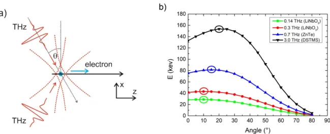
There is a potential to extend the interaction length between the electron and the accelerating part of the THz pulse and approach the velocity matching condition between the THz pulse and the electron by tilting the THz beam propagation direction by an angle θ (figure 4(a)). For tilted THz beams, the longitudinal (accelerating)component of the THz pulse is decreased, but the
Figure 4.(a)Electron acceleration setup with two single-cycle THz pulses propagating in opposite directions at a beam tilt angleq.(b)The final kinetic energies of the electron in case of differentqangles. A THz pulse energy of 1 mJ has been assumed in each case.
Table 2.Final energies of electrons accelerated by THz pulses with 1 mJ energies focused to spot sizesw0=l.
Frequency
Electricfield of the THz pulses
Tilt angle(q)
Final electron energy
0.14 THz 1.74 MV cm−1 10° 29.0 keV
0.3 THz 5.21 MV cm−1 10° 43.4 keV
0.7 THz 16.9 MV cm−1 15° 81.4 keV
3.0 THz 113 MV cm−1 20° 153 keV
J. Phys. B: At. Mol. Opt. Phys.51(2018)134004 Z Tibaiet al
interaction length between the electron and the accelerating part of the THz pulse is extended, potentially resulting in a higher electron energy. The calculated final kinetic energies as func- tions of the tilt angle are shown infigure4(b). The optimum tilt angles and achieved electron energies are summarized in table2 for the different types of THz source with 1 mJ pulse energies considered here. In case of the DSTMS source with 3 THz central frequency and the highest accelerated electron energy, an energy gain of 17% can be achieved for the 20° optimal tilt angle, as compared to the untilted(θ=0°)case. The increased electron energy reaches about 150 keV. At still higher electron energies, one can expect an even larger energy gain at larger optimal tilt angles.
4. Acceleration of an electron bunch
Simulations were carried out with realistic electron bunches as well. The scheme of the setup is similar to figure 4(a), however not a single electron is considered. It is supposed
that a THz pulse pair is focused on a gas jet, where the electrons are generated. A high-power fourth harmonic beam of 1μm wavelength is focused on the gas jet
⋅ -
(3 10161 cm 3)[32], where it ionizes the krypton molecules (4th harmonic and three photon absorption), and electron bunch with 0.5 eV average energies are generated. A laser- ionized gas jet can become an ideal electron source because it enables control of both the charge and the electron bunch size, and a controlled injection of the electrons into the counter- propagating THz beams. Furthermore, it allows the tilted propagation setup, contrary to other sources that do not allow it(for example, photocathodes). Calculations were performed with different ionized region sizes in the gas jet to define the optimal value. The distribution of electrons was Gaussian in the initial case and the total charge was 1 pC (electron and krypton ion, respectively). The THz pulses propagate through the gas jet with an optimal angle (according to figure 4(b)) and perfect synchronization, and accelerate the electrons. The THz pulses were considered to be generated in four different sources, with pulse energies of 1 mJ. The pulse parameters were taken from table1.
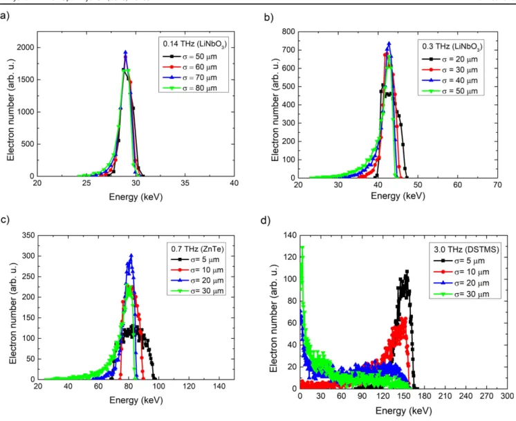
Figure 5.The energy spectra of electron bunches, accelerated by the THz pulse pairs, with 1 mJ energies per pulse, propagating with optimal angle to the electron path.
The numerical simulations were performed using a general particle tracer(GPT)and a self-developed program code, which accounts for the space charge effect. The results are shown in figure 5. In our calculations, the energy spread of accelerated electrons was investigated for different sizes of electron bunch.
According to our calculation 70μm, 40μm, 20μm and 5μm (σ)are the optimal bunch sizes for 0.14, 0.3, 0.7 and 3.0 THz mean frequencies, respectively. We have to note that for larger ionizing laser beam waist the initial electron beam size will be larger, too. This causes some limitations to the feasibility of the setup for short wavelength (for example DSTMS source). In cases where the size of THz mean wavelength is almost the same as the bunch size, the energy spread is larger because the electrons situated at different parts of the bunch feel different accelerating fields of the THz pulse. Furthermore, in case of reduction of bunch size, the influence of space charge is larger
(for constant bunch charge). Because of the higher space charge, the energy spread is also higher. Our calculations show that the optimal initial bunch size is larger in the case of the THz wavelength is larger. According to our calculations with THz sources of 0.14, 0.3, 0.7 and 3.0 THz mean frequencies, 29.0 keV, 43.4 keV, 81.4 keV and 153 keV peak electron energy can be achieved, respectively. The energy spread(ΔE/E)values are 4, 6, 9.5 and 15%, at the optimal sizes, respectively. This way electron bunches can be created, which can be used in chemical and biological research.
5. Post-acceleration of a single electron
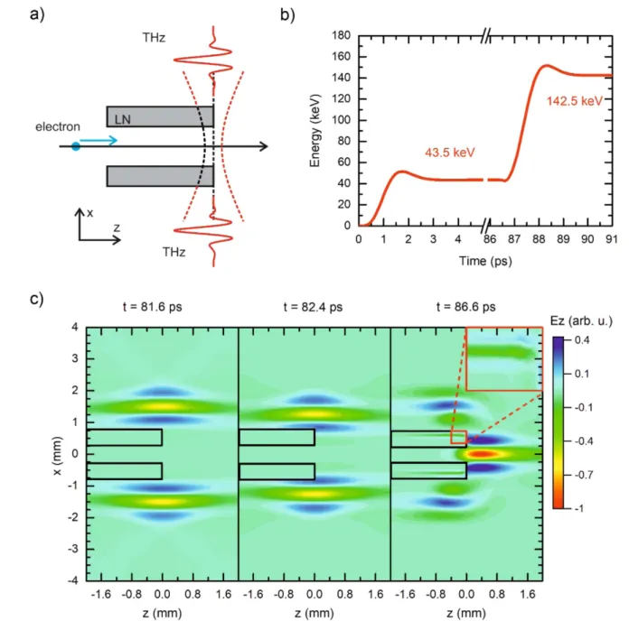
Post-acceleration of accelerated electrons is also feasible by focusing further THz pulses along the path of the electrons with
Figure 6.Electron post-acceleration setup(a), the energy evolution energy of the two staged accelerated electrons with LN plates in the THz beam path(b), the THz pulse evolution at different time points(c).
J. Phys. B: At. Mol. Opt. Phys.51(2018)134004 Z Tibaiet al
goes through the LN, where its velocity and wavelength is decreased(figure6(c)). The other half of the THz beam can still propagate through the vacuum, create a standing wave in the axis, and let the perfect synchronization with the pre-accelerated electrons. This separation is shown in figure 6(c)at three dif- ferent time steps(before the THz reaches the LN, at that point when it reaches, and that point when the synchronization is perfect). At that time, when the injection is perfect, the electric field inside the gap almost disappears. Thefield evolution was calculated with FDTD numerical code.
In the calculations 1 mJ THz pulse energies were con- sidered, the frequency of the pulses was 0.3 THz, the beam waist was equal to the wavelength. In the calculation, we used the pre-accelerated electron from thefirst stage, and we post- accelerated it. The results obtained with this structure are summarized infigure6(b). After this stage, the electrons are accelerated to 143 keV energy. We note that when the same THz pulses are applied, higher energy gain can be achieved in the post-acceleration stage than in thefirst acceleration stage.
6. Conclusion
Electron acceleration to relativistic energies by counter-pro- pagating focused THz pulses was proposed and numerically investigated. Investigations were performed at different THz frequencies based on experimentally achieved or numerically calculated THz pulse parameters. The acceleration rate depends on the phase of THz pulses and on the angle between the propagation direction of the electrons and the THz pulses.
The optimal THz propagation angle is higher at higher elec- tron velocity. Final electron energies of 150 keV can be achieved by the proposed acceleration setup in case of elec- tron bunches 20μm using THz pulses with 1 mJ energies. In the case of post-acceleration, the slowing impact of the positive part of the THz pulse shape can be reduced by pla- cing a dielectric material(for example LiNbO3)in the path of the pulse propagation, delaying half of the THz beam.
Acknowledgments
The project has been supported by the European Union, co-financed by the European Social Fund Grant no.:
A Sharma https://orcid.org/0000-0001-9021-4296
References
[1] Malka V, Faure J, Gauduel Y A, Lefebvre E, Rousse A and Phuoc K T 2008Nat. Phys.4447
[2] Malka V 2012Phys. Plasmas19055501
[3] Plettner T, Lu P P and Byer R L 2006Phys. Rev. Accel. Beams 9111301
[4] Peralta E Aet al Nature50391
[5] Carbajo S, Nanni E A, Wong L J, Moriena G, Keathley P D, Laurent G, Dwayne Miller R J and Kärtner F X 2016Phys.
Rev. Accel. Beams19021303
[6] Wong L J, Hong K-H, Carbajo S, Fallahi A, Piot P, SoljačićM, Joannopoulos J D, Kärtner F X and Kaminer I 2017Sci.
Rep.711159
[7] Fülöp J A, Pálfalvi L, Klingebiel S, Almási G, Krausz F, Karsch S and Hebling J 2012Opt. Lett.37557 [8] Vicario C, Ovchinnikov A V, Ashitkov S I, Agranat M B,
Fortov V E and Hauri C P 2014Opt. Lett.396632 [9] Sell A, Leitenstorfer A and Huber R 2008Opt. Lett.33
2767
[10] Ruchert C, Vicario C and Hauri C P 2012Opt Lett.37899 [11] Shalaby M and Hauri C P 2015Nat. Commun.65976 [12] Fülöp J Aet al2014Opt. Express2220155
[13] Gy Pet al2016Opt. Express2423872
[14] Fülöp J A, Gy P, Monoszlai B, Andriukaitis G, Balciunas T, Pugzlys A, Arthur G, Baltuska A and Hebling J 2016Optica 31075
[15] Hebling J, Fülöp J A, Mechler M I, Pálfalvi L, Tőke C and Almási G 2011 arXiv:1109.6852
[16] Curry E, Fabbri S, Musumeci P and Gover A 2016New J.
Phys.18113045
[17] Fallahi A, Fakhari M, Yahaghi A, Arrieta M and Kärtner F X 2016Phys. Rev. Accel. Beams19081302
[18] Tibai Z, Pálfalvi L, Fülöp J A, Irman A, Almási G,
Schramm U, Cowan T and Hebling J 2014LA3NET Conf.
(Germany: Dresden)
[19] Wei Yet al2018Nucl. Instrum. Meth.A877173
[20] Fakhari M, Fallahi A and Kärtner F X 2017Phys. Rev. Accel.
Beams20041302
[21] Kärtner F Xet al2016Nucl. Instrum. Meth.A82924 [22] Vinatier T, Assmann R W, Dorda O, Lemery F and
Marchetti B 2017J. Phys.: Conf. Ser.874012042 [23] Nanni E A, Huang W R, Hong K-H, Ravi K, Fallahi A,
Moriena G, Dwayne Miller R J and Kärtner F X 2015Nat.
Commun.68486
[24] Huang W R, Nanni E A, Ravi K, Hong K-H, Fallahi A, Wong L J, Keathley P D, Zapata L E and Kärtner F X 2015 Sci. Rep.514899
[25] Wong L J, Fallahi A and Kärtner F X 2013Opt. Express219792 [26] Huang W R, Fallahi A, Wu X, Cankaya H, Calendron A-L,
Ravi K, Zhang D, Nanni E A, Hong K-H and Kärtner F X 2016Optica31209
[27] Pálfalvi L, Fülöp J A, Gy T and Hebling J 2014Phys. Rev.
Accel. Beams17031301
[28] Sharma A, Tibai Z and Hebling J 2016Phys. Plasmas23063111
[29] Pálfalvi L, Gy T, Tokodi L, Márton Z, Fülöp J A, Almási G and Hebling J 2017Opt. Express2529560 [30] Wu Xet al2016Opt. Express2421059
[31] Fülöp J Aet al2011Opt. Express1915090
[32] Yu L-L, Esarey E, Schroeder C B, Vay J-L, Benedetti C, Geddes C G R, Chen M and Leemans W P 2014Phys. Rev.
Lett.112125001
J. Phys. B: At. Mol. Opt. Phys.51(2018)134004 Z Tibaiet al