PROCEEDINGS OF SPIE
SPIEDigitalLibrary.org/conference-proceedings-of-spie
Single-shot surface ablation and transient reflectivity changes of
optical glasses induced by 34 fs laser pulses
A. Andrásik, R. Flender, J. Budai, T. Szörényi, B. Hopp
A. Andrásik, R. Flender, J. Budai, T. Szörényi, B. Hopp, "Single-shot surface ablation and transient reflectivity changes of optical glasses induced by 34 fs laser pulses," Proc. SPIE 11034, Short-pulse High-energy Lasers and Ultrafast Optical Technologies, 110340T (26 April 2019); doi:
10.1117/12.2523006
Event: SPIE Optics + Optoelectronics, 2019, Prague, Czech Republic
Downloaded From: https://www.spiedigitallibrary.org/conference-proceedings-of-spie on 07 May 2019 Terms of Use: https://www.spiedigitallibrary.org/terms-of-use
Single-shot surface ablation and transient reflectivity changes of optical glasses induced by 34 fs laser pulses
A. Andrásik
1,2, R. Flender
1,3, J. Budai
1,T. Szörényi
1,3, B. Hopp
11 - Department of Optics and Quantum Electronics, University of Szeged, H-6720 Szeged, Dóm tér 9., Hungary
2 - Department of Photonics and Laser Research, Interdisciplinary Excellence Centre, University of Szeged
3 - ELI-ALPS, ELI-HU Non-Profit Ltd. H-6720 Szeged, Dugonics tér 13.
ABSTRACT
Results of a comparative study on single-shot surface ablation of commercial optical glasses together with the transient reflectivity enhancement during the process are reported. Three types of optical glasses: Schott’s BOROFLOAT®, BK7 and B270 are ablated by single pulses of 34 fs duration at 800 nm central wavelength of the TeWaTi laser systems at University of Szeged, varying systematically both the pulse energy and the beam diameter on the surface, while recording the reflected signal. The depth and diameter of the ablated holes are characterized ex-situ by a DEKTAK profilometer.
Very similar ablation characteristics have been determined: Above the ablation thresholds at 5.84±0.21 Jcm-2 (1.72±0.06*1014 Wcm-2), 6.43±0.56 Jcm-2 (1.89±0.16*1014 Wcm-2) and 5.86±0.31 Jcm-2 (1.75±0.09*1014 Wcm-2) for BOROFLOAT®, BK7 and B270, respectively, both the diameter and the depth of the holes produced show logarithmic increase as a function of pulse energy/fluence until saturating above ~18 Jcm-2. On the contrary, significant differences have been obtained in the time integrated transient reflectivities, with the highest absolute values measured for the BOROFLOAT® glass. Strong spot size dependence has been revealed: The reflectivity increases monotonously with increasing pulse energy for all spot sizes, with decreasing absolute values/slopes with decreasing spot areas. Different reflectivities belong to the same fluence/intensity depending on the actual spot size, consequently the fluence/intensity alone does not define unambigously the characteristics of the plasma. The correct description of the changes in reflectivity requires the specification of the spot size together with the pulse energy/fluence/intensity.
Keywords: ablation, femtosecond, single-shot, transient reflectivity, optical glasses, plasma mirror
1. INTRODUCTION
Laser ablation of transparent dielectrics by nanosecond pulses is a challenging task. With enhanced absorption and reduced thermal effects pulse shortening offers a straightforward approach [1]. When exceeding an intensity threshold the interaction of high-intensity ultrashort pulses with the surface to be processed results in the generation of a high density plasma due to the laser induced optical breakdown of the material. The effect of the plasma mirror formation [2]
is twofold: From the materials engineer’s point of view its development should be avoided since it decreases the effectivity of the ablation. On the other hand cleaning with plasma mirror is an effective technique of improving the temporal contrast of high-intensity ultrashort pulses.
Many papers have been published on femtosecond laser ablation of dielectrics [e.g. 3, 4] and plasma mirror related transient reflectivity enhancement [e.g. 5-7], the large majority dealing with fused silica. Reports on optical glasses are astonishingly scarce. Though it is highly recommended to investigate simultaneously the ablation properties and the accompanying changes in the transient reflectivity in order to optimize and precisely control the processes [8, 9], accounts of ablation characteristics along with transient reflectivity changes are apparently missing from the literature.
Short-pulse High-energy Lasers and Ultrafast Optical Technologies, edited by Pavel Bakule, Constantin L. Haefner, Proc. of SPIE Vol. 11034, 110340T · © 2019 SPIE
CCC code: 0277-786X/19/$18 · doi: 10.1117/12.2523006
Proc. of SPIE Vol. 11034 110340T-1 Downloaded From: https://www.spiedigitallibrary.org/conference-proceedings-of-spie on 07 May 2019
Terms of Use: https://www.spiedigitallibrary.org/terms-of-use
In this contribution results of a comparative study on single-shot surface ablation of three types of commercial optical glasses: BOROFLOAT®, BK7 and B270, together with the transient reflectivity enhancement during the process are reported varying systematically both the pulse energy and the beam diameter on the surface, while recording the reflected signal.
2. EXPERIMENTAL
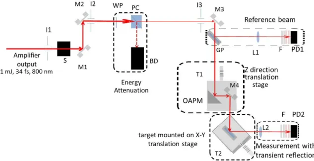
The TeWaTi laser systems at University of Szeged consisting of a modelocked laser oscillator (Spectra-Physics Rainbow™ CEP4, 7 fs, CEP stabilized, 800 nm, 75 MHz), and a Ti:sapphire based CPA amplifier provided 34 fs ± 0.16 fs pulses of 1 mJ energy and better than 1 % (RMS) energy stability. The temporal contrast of the pulses after amplification was 107 as measured by a third order cross-correlator (SEQUOIA from Amplitude Technologies). The experimental setup is sketched in Figure 1. In order to cut single pulses from the output of the amplifier an optical shutter (Thorlabs Inc. SH05) with a benchtop shutter controller (Thorlabs Inc. SC10) was used. The pulse energy was varied by a polarization-rotation based beam attenuator. Pulse energies were measured with a Gentec QE50SP-H-MT-V0 energy meter. The reproducibility of the energy measurements was better than 5 %. An off-axis parabolic mirror (Thorlabs Inc.
MPD169-P01) of 152.4 mm reflected focal length (RFL) and an F-number of f/19 focused the beam onto the target surface at an angle of 45°.
Uncoated BOROFLOAT® (Edmund Optics: ID #48-542), N-BK7 (Eksma Optics: ID 215-0222), B270® Superwhite (Edmund Optics: ID #48-538) optical glass pieces were used as targets. Pristine surface was ensured shot-to-shot by positioning the target using translation stages. The beam reflected from the sample surface was focused by a lens with a focal length of 35 mm and aperture size of 25.4 mm onto the photodiode PD2 (Thorlabs DET36/A). This photodiode measured the reflected signal, scaling with the energy of the reflected pulse, during each shot. Longpass filters of 620 nm cutoff wavelength served to exclude the light of the occurring plasma and the stray light from the 532 nm amplifier pump. Reflective filters before the photodiodes reduced the intensity to acceptable levels.
Figure 1: Scheme of the laser material processing setup. M1-M4: flat silver mirrors; I1- I3: iris diaphragms; S: optical shutter; WP: half-wave plate; PC: polarization beamsplitter cube; BD: beam dumper; T1: translation stage toward z- direction; T2: translation stages toward x-y directions; OAPM: off-axis parabolic mirror; GP: glass plate; L1-L2: focusing bi-convex lens; F: filters; PD1-PD2: photodiodes.
Hole matrices were ablated at different pulse energies in such a way that at each pulse energies 11 holes were ablated.
The depth and the diameter of the ablated holes were determined by recording line scans along the minor axis of the
Proc. of SPIE Vol. 11034 110340T-2 Downloaded From: https://www.spiedigitallibrary.org/conference-proceedings-of-spie on 07 May 2019
Terms of Use: https://www.spiedigitallibrary.org/terms-of-use
holes by a stylus profilometer (Veeco DEKTAK8 surface profiler). The actual data were averaged for the 11 holes ablated at each pulse energy.
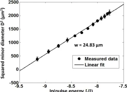
To determine the actual diameter of the beam on the samples surface the well-known expression connecting the ablated hole diameter with the fluence, and thus pulse energy was applied [10]:
𝐷2= 2𝑤2ln(𝐹
𝐹𝑡ℎ), (1)
where w is 1/e2 radius of the beam, F and Fth stand for the peak and ablation threshold fluences, respectively. The linear relationship shown in Figure 2 indicates that even though the measurements were carried out in air ionization was not occurring at 24.83 µm beam radius.
Figure 2: Determination of radii of the beam on the surface of the target using linearization of the recorded hole diameter.
The target material was a B270 glass.
The actual peak fluences and intensities were calculated according to the following expressions:
𝐹 = 2𝐸𝑝
𝜋𝑤2√2 (2)
𝐼 = 2𝐸𝑝
𝜋𝑤2𝜏√2 (3)
where Ep and denote pulse energy and the full width of half maximum (FWHM) pulse duration, respectively. The ablation threshold fluence/intensity data were determined according to Eqs. (1)-(3) by means of diameter-regression technique [4].
3. RESULTS
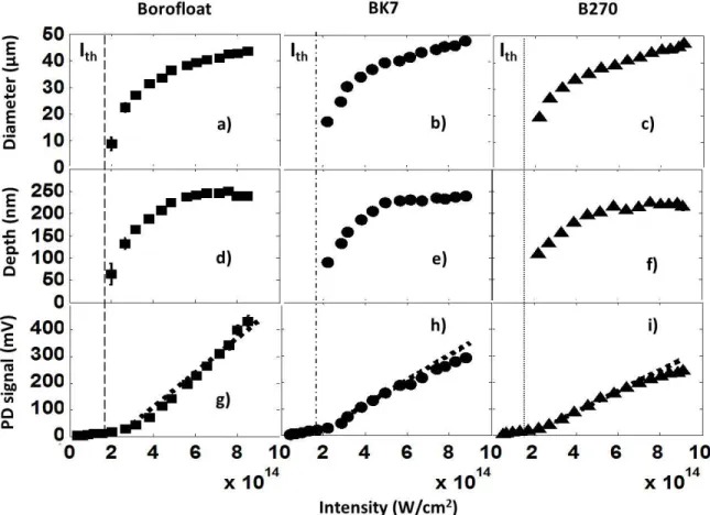
The diameter and depth of the ablated holes and the time integrated transient reflectivities characterized by the signal of photodiode PD2 which scales with the energy of the pulse reflected from the glass surface are plotted as a function of laser intensity for the BOROFLOAT®, BK7 and B270 glasses in Figure 3. While in each case several experimental series were carried out, since the repeatability of the measurements was fairly good only one data set is presented for each glass type in Figure 3. The averaged ablation threshold intensities as derived using the diameter-regression
Proc. of SPIE Vol. 11034 110340T-3 Downloaded From: https://www.spiedigitallibrary.org/conference-proceedings-of-spie on 07 May 2019
Terms of Use: https://www.spiedigitallibrary.org/terms-of-use
technique: 1.72±0.06 1014, 1.89±0.16 1014 and 1.75±0.09 1014 W/cm2 for BOROFLOAT®, BK7 and B270, respectively, were found to be equal within measurement error.
Above the ablation threshold intensities the diameter values increase logarithmically with increasing laser intensity for all glasses and reach similar maximal values (~45 m) in the investigated intensity range (Figure 3a-c). The hole depths increase with increasing laser intensities above the ablation threshold and show saturation for all investigated glasses (Figure 3d-f). The dependencies are similar with minor differences in the maxima: into BOROFLOAT® and BK7 ~250 nm deep holes could be ablated, while for B270 the maximum hole depth is only 220 nm. Saturation starts above 6×10¹⁴ W/cm2 in the case of BOROFLOAT®, while BK7 and B270 exhibit saturation already above 5.5 ×10¹⁴ W/cm2 and 5 ×10¹⁴ W/cm2, respectively.
The photodiode signal vs. intensity functions can be described by two straight sections of different slopes joining at the ablation threshold, for all three glasses (Figure 3g-i). Below the ablation threshold the slopes match within measurement error, while at higher intensities they deviate. The steepest increase was recorded for BOROFLOAT®, while the smallest appeared for B270. Accordingly the largest PD signal values were observed in the case of the BOROFLOAT® samples (~400 mV), while smaller maxima characterise the BK7 and B270 glasses: 300 and 250 mV, respectively. Furthermore, for the latter two glasses signs of saturation appear at the highest intensities, further supporting that the transient reflectivity of the three glasses behaves differently.
Figure 3: Dimensions of the ablated holes and the behavior of the reflectivity as a function of intensity for the three glass types. The minor diameter of the beam on the samples was 50±2 µm.
Proc. of SPIE Vol. 11034 110340T-4 Downloaded From: https://www.spiedigitallibrary.org/conference-proceedings-of-spie on 07 May 2019
Terms of Use: https://www.spiedigitallibrary.org/terms-of-use
The results presented up to this paragraph referred to studies performed keeping the beam diameter fixed. To answer the intriguing question whether the ablation properties and plasma characteristics depend on the actual beam radius [11, 12]
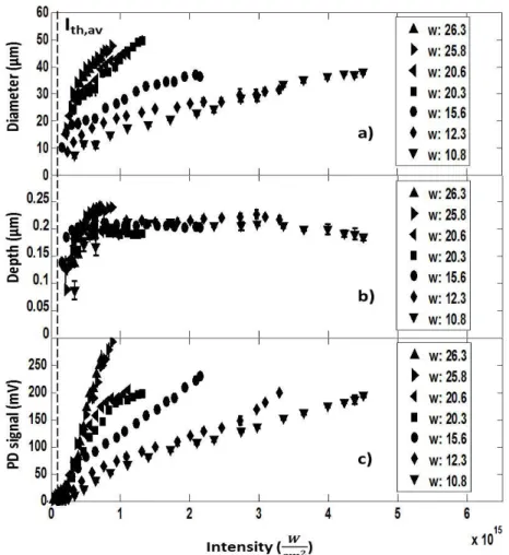
a new series of experiments has been initiated aimed at the determination of the dependence of the hole dimensions and the transient reflectivity on the intensity varying the size of the processed area, ie. the spot diameter. The results are summarized in Figure 4.
Figure 4:Dimensions of the ablated holes and the behavior of the reflectivity as a function of intensity for different spot sizes on the surface of a BK7 glass. The numbers listed refer to the beam radii given in micrometer.
According to Figure 4a the hole diameters increase with the intensity monotonously for all beam sizes, however the rate of the increase depends strongly on the actual diameter of the processing laser beam on the sample surface. For the largest 1/e2 beam radii (>25 m) the diameter of the holes starts to grow steeply with increasing intensity, and the maximal ~50 m diameters are reached already at 1×10¹⁵ W/cm2. The slopes decrease with decreasing beam radii, and accordingly the highest diameters are reached at the higher intensities. In the case of the two smallest beam radii (12.3 and 10.8 m) the highest diameters (approaching 40 m) are observed only at 4×10¹⁵ W/cm2. When analyzing the hole depth values as a function of laser intensity (Figure 4b) two branches can be distinguished. In both sets the depth increases steeply at lower intensities. The depth vs. intensity functions separate according to the spot diameters:
exceeding 25 m radii the hole depth increases up to ~250 nm, while below this radius the depth saturates around 200 nm. According to Figure 4c, the variation of reflectivity as a function of intensity also exhibits clear dependence on the beam radius. For all beam radii the reflectivity increases monotonously with intensity. At lower intensities a steep linear increase can be observed, followed by a decrease in slope. The intensity where the slope of the reflectivity increase changes coincides with the intensity where saturation of the hole depth appears. The two linear segments in the reflectivity data separate most clearly for beam radii of 20.6 and 20.3 m. Naturally for the largest beam radii (>25 m)
Proc. of SPIE Vol. 11034 110340T-5 Downloaded From: https://www.spiedigitallibrary.org/conference-proceedings-of-spie on 07 May 2019
Terms of Use: https://www.spiedigitallibrary.org/terms-of-use
the second linear segment can not be observed, as in this case the intensity (below 1×10¹⁵ W/cm2) is not high enough to reach the point of separation of the two linear segments. The common feature of all functions is that the appearance of the reflectivity vs. intensity curves is determined by the spot size: the larger the beam diameter the higher the slope. As an example: for the largest beam radii (>25 m) 300 mV photodiode signal is reached already below 1×10¹⁵ W/cm2, while in the case of the smallest beam radii (12.3 and 10.8 m) maximum 200 mV was recorded.
4. DISCUSSION
The comparison of the results with literature data is not an easy task because of the complicated interdependencies due to the large number of parameters that can be varied during the execution of the experiments while having significant effect on the answer of the material to be processed. Another issue is that the vast majority of the studies deal with fused silica, the investigations performed on glasses being very scarce.
As the glasses studied here are silicate-types, comparison of their properties with fused silica is rational. The fluence threshold values reported by the Marseille group [ 4, 8, 13] converted into intensity thresholds taking into account the pulse durations give threshold intensities of 1.86 × 10¹⁴ 𝑊
𝑐𝑚2, 8 × 10¹³ 𝑊
𝑐𝑚2, 3.4 × 10¹³ 𝑊
𝑐𝑚2, 1.47 × 10¹³ 𝑊
𝑐𝑚2 and 4.89 − 9.44 × 10¹² 𝑊
𝑐𝑚2 for 7, 30, 100, 300 and 450 fs pulses, respectively for fused silica. Puerto [14] obtained an ablation threshold of 4.5 × 10¹³ 𝑊
𝑐𝑚2 for 120 fs pulses. While the former values are assigned to a processing beams with 4.65 µm radius [4, 8, 13] the latter one belongs to minor/major radii of 25/38 µm [14]. In line with the general consensus these data also reveal that the thresholds decrease with increasing pulse duration. What is less emphasized: the thresholds sensitively depend on the spot size: an increase in diameter results in an increase in the threshold. Since the beam radii in our experiments were much higher than those reported in [4, 8, 13] and our pulses were shorter than those used in [14]
our threshold values fit perfectly to the literature. For BOROFLOAT® glass Ben-Yakar [15] reported an ablation threshold of 1.25 × 10¹³ 𝑊
𝑐𝑚2 for 200 fs pulses with a processing beam characterized by 5.9 µm radius on the sample, while Grehn [16] obtained 3.67 × 10¹³ 𝑊
𝑐𝑚2 by a processing beam with 16.2 µm radius and 120 fs pulse duration. These data are in line with both those of fused silica and derived by us. Together with the result that the three glasses investigated by us possess very similar characteristics, the conclusion is that the thresholds of the optical glasses do not differ significantly from that of the fused silica. Nevertheless further studies are necessary to fill the gaps in the dependence of the material characteristics on process parameters in general and the pulse duration and spot size in particular.
As reported in one of the relevant papers of the Marseille group [8] the diameter of the holes ablated in fused silica increases monotonously with intensity, characterized by two segments of different shapes: a logarithmically increasing and a less steep, leveling one. The two parts join at I/Ith normalized intensity of 2. This behavior was reported for pulse durations in the whole 7 - 450 fs range investigated [8]. The diameter vs. intensity curves depicted in Figure 3a-c show the same characteristics with different hole diameter values according to the difference in the spot sizes. The dependence of the depth of the holes on the intensity given in Figure 3d-f is the same as reported in [8]: When exceeding 2 × I/Ith the steeply increasing curves start to saturate. Again, the absolute values differ: while in [8] the maxima are 100 and 150 nm for 7 and 30 fs pulses, respectively, into BOROFLOAT® and BK7 ~250 nm deep holes could be ablated, while for B270 the maximum hole depth was only 220 nm. The effect behind the saturating behavior is the enhanced transient reflectivity of the plasma generated on the irradiated area [8, 9, 17, 18].
Transient reflectivity characteristics of the plasma generated on the surface of silica along with the depth of ablated holes at 25 µm focused beam radius and 120 fs pulse duration, while transient changes in the optical properties of fused silica surface as a function of intensity for 450 fs pulses are reported in [19] and [9], respectively. Though the applied laser parameters differ, the transient reflectivity described in these papers exhibits similar dependence on the intensity as the curves in Figure 3h-i for BK7 and B270 glasses.
To understand the differences observed in the reflectivity of the three glasses (Figure 3g-i) the origin of the two sections below and above the ablation threshold has to be found first. Obviously, the reflectivity below the ablation threshold is the result of the reflection from the unchanged glass surface. Since the refractive indices of the three glasses are practically the same the permanent reflectivity curves coincide. Exceeding the ablation threshold the different slopes
Proc. of SPIE Vol. 11034 110340T-6 Downloaded From: https://www.spiedigitallibrary.org/conference-proceedings-of-spie on 07 May 2019
Terms of Use: https://www.spiedigitallibrary.org/terms-of-use
already indicate that further processes are involved, and new mechanisms govern the reflectivity. At such high intensities the energy transferred to the electron system ionizes the material and a reflecting dense electron cloud, a plasma mirror is formed. The differing slopes above the ablation threshold indicate that the plasma mirrors formed on the surface of the three glasses are different.
Supposing that number/density of electrons participating in the formation of the plasma is proportional to the volume of the laser-matter interaction, thereby to the ablated volume, this volume has been calculated taking into account that the shape of the ablated region was an elliptic cylinder, as:
𝑉 = 𝑑2𝜋√2
4 ℎ, (4)
where d and h denote the smaller diameter and depth of the ablated spot, respectively. The equation supposes that the larger diameter of the ellipse can be calculated according to the angle on incidence (45°) of the ablating laser pulse.
Figure 5: The ablated volume as a function of pulse energy. The beam radius was 25 ± 2 µm for all measurement sets and glasses.
As Figure 5 demonstrates the ablated volume vs. pulse energy curves of the three glasses coincide within measurement error. The ablated volume increases with increasing pulse energy linearly up to 250 J. This value marks the onset of the leveling in ablated hole depth. Above this energy the rise in ablated volume slows down and a less steep linear dependence occurs. At the highest pulse energies roughly 550 m3 material is ablated in all cases. This supports that the three glasses behave akin from the point of view of ablation, and it also highlights that the differences observed in the reflectivity can’t be directly connected with the amount of ablated material.
To understand the apparent discrepancies, it should be kept in mind that the time scale of the processes involved in the two phenomena, plasma formation and ablation, are significantly different. By measuring the reflectivity of the femtosecond pulse the first step of a complex process leading to ablation, a much longer effect, materializing after several picoseconds, if not even nanoseconds after the interaction of the laser pulse and surface, is examined. According to our findings though this first step, i.e. the initial plasma formation is different for the three glasses, the subsequent thermal processes smear out the differences.
To further analyze the differences observed in the plasma mirror reflectivity the average number of electrons in 1 mol glass has been estimated based on their composition. The number of electrons involved in the creation of each component (SiO2, B2O3, Na2O, …) was determined and averaged according to the molar concentrations. According to
Proc. of SPIE Vol. 11034 110340T-7 Downloaded From: https://www.spiedigitallibrary.org/conference-proceedings-of-spie on 07 May 2019
Terms of Use: https://www.spiedigitallibrary.org/terms-of-use
the calculation the highest number of electrons, 4.19 is involved in the formation the BOROFLOAT® glass, which exhibits the highest plasma mirror reflectivity. For BK7 with the second highest plasma mirror reflectivity the average electron number decreases to 3.86, and the lowest number of electrons, 3.48 belongs to B270 exhibiting the lowest reflectivity. It can be concluded that the variation of the integrated plasma mirror reflectivity is in line with the average number of electrons involved in the glass formation.
The majority of reports describe ablation characteristics measured at fixed spot size, very limited number of studies investigating the dependence of the ablation properties on spot size can be found [20, 21, 22]. The study proving the phenomenon of spot size dependence of ablation characteristics for fused silica was carried out only in a limited range of beam radii of less than 10 µm [23]. The results related to diameter and depth of the ablated holes described in Figure 4a- b for BK7 glass can thus be treated as a gap-filling contribution to the reported literature data. With decreasing spot size the variation of hole diameter and depth on the intensity approaches the behavior and even the absolute values reported for smaller beam radii [8]. This finding indicates that the spot size should play a major role in the intensity dependence of both of hole diameter and depth.
The reflectivity vs. intensity functions shown in Figure 4c taken for BK7 glass at different beam radii are supposed to be a novel approach to the presentation of the dependence of transient reflectivity on spot size, as the existing publications touching the problem [11, 12] report z-scan instead of energy-scan. In these studies, performed using 40 fs [11] and 30 fs pulses [12] similar behavior as depicted in Figure 4c was demonstrated: decreasing transient reflectivity for sample positions closer to the focus i.e. for decreasing beam radii. Nevertheless, spot size dependence of the transient reflectivity as a function of intensity is not explicitly stated in the literature.
5. CONCLUSION
This paper summarizes experimental results on the characteristics of the holes and the time-integrated transient reflectivity for three types of optical glasses ablated by single pulses of 34 fs duration.
Ex-situ characterization of the ablated holes revealed that all three glasses investigated behave akin in respect of both the ablation thresholds (1.72±0.06 1014, 1.89±0.16 1014 and 1.75±0.09 1014 W/cm2 for BOROFLOAT®, BK7 and B270, respectively), and the dependences of hole diameter and depth as a function of intensity. In contrast, noticeable differences were demonstrated in the variation of the transient reflectivity. This experience can be attributed to the differences in the glass composition: the variation of the integrated plasma mirror reflectivity is in line with the difference in the average number of electrons available for plasma formation in the glasses.
The variation of the diameter and depth of the ablated holes and the transient reflectivity on intensity derived for BK7 glass exhibit a clear dependence on spot size. This result draws attention to the role of spot size in determining both the ablation characteristics and the transient reflectivity. As a consequence, in order to be able to give the fluence/intensity dependence of the hole diameter, depth, and the reflectivity of the plasma unambiguously, it is necessary to define the spot size.
These first results pave the way for optimization of surface microstructuring of commercial glasses and their efficient application in plasma mirror experiments.
ACKNOWLEDGEMENTS
This work was supported by ELI-ALPS, ELI-HU Non-Profit Ltd. H-6720 Szeged, Dugonics tér 13 in the frame of GINOP-2.3.6-15-2015-00001 and ELI_GINOP_4_0125 and by the Ministry of Human Capacities, Hungary grant 20391-3/2018/FEKUSTRAT. The authors wish to thank Ádám Börzsönyi, Mikhail Kalashnikov and Csaba Vass from ELI-ALPS, ELI-HU Non-Profit Ltd. H-6720 Szeged, Dugonics tér 13 for valuable discussions.
Proc. of SPIE Vol. 11034 110340T-8 Downloaded From: https://www.spiedigitallibrary.org/conference-proceedings-of-spie on 07 May 2019
Terms of Use: https://www.spiedigitallibrary.org/terms-of-use
REFERENCES
[1] Gattas, R. R. and Mazur, E., “Femtosecond laser micromachining in transparent materials”, Nature Photonics 2, 219 - 225 (2008).
[2] Kapteyn, H. C., Murname, M. M., Szoke, A., Falcone, R. W., “Prepulse energy suppression for high-energy ultrashort pulses using self-induced plasma shuttering”, Opt. Lett. 16(7), 490-492 (1991).
[3] Lenzner, M., Krüger, J., Sartania, S., Cheng, Z., Spielmann, Ch., Mourou, G., Kautek, W. and Krausz, F.,
“Femtosecond Optical Breakdown in Dielectrics”, Phys. Rev. Lett. 80(18), 4076-4079 (1998).
[4] Sanner, N., Utéza, O., Bussiere, B., Coustillier, G., Leray, A., Itina, T. and Sentis, M., “Measurement of femtosecond laser-induced damage and ablation thresholds in dielectrics”, Appl. Phys. A 94, 889-897 (2009).
[5] Ziener, Ch., Foster, P. S., Divall, E. J., Hooker, C. J., Hutchinson, M. H. R., Langley, A. J. and Neely, D.,
“Specular reflectivity of plasma mirrors as a function of intensity, pulse duration, and angle of incidence”, Journal of Applied Physics 93(1), 768-770 (2003).
[6] Dromey, B., Kar, S., Zepf, M. and Foster, P., “The plasma mirror-A subpicosecond optical switch for ultrahigh power lasers”, Review of Scientific Instruments 75(3), 645-649 (2004).
[7] Doumy, G., Quére, F., Gobert, O., Perdrix, M., Martin, Ph., Audebert, P., Gauthier, J. C., Geindre, J.-P. and Wittmann, T., “Complete characterization of a plasma mirror for the production of high-contrast ultraintense laser pulses”, Physical Review E 69, 026402 (2004).
[8] Utéza, O., Sanner, N., Chimier, B., Brocas, A., Varkentina, N., Sentis, M., Lassonde, P., Légaré, F. and Kieffer, J. C., “Control of material removal of fused silica with single pulses of few optical cycles to sub-picosecond duration”, Appl. Phys. A 105, 131-141 (2011).
[9] Varkentina, N., Sanner, N., Lebugle, M., Sentis, M. and Utéza, O., “Absorption of a single 500 fs laser pulse at the surface of fused silica: Energy balance and ablation efficiency”, Journal of Applied Physics 114, 173105 (2013).
[10] Liu, J. M., “Simple technique for measurements of pulsed Gaussian-beam spot sizes”, Opt. Lett. 7(5), 196-198 (1982).
[11] Shaw, B. H., Steinke, S., van Tilborg, J. and Leemans, W. P., “Reflectance characterization of tape-based plasma mirrors”, Phys. Plasmas, 23, 063118 (2016).
[12] Obst, L., Metzkes-Ng, J., Bock, S., Cochran, G. E., Cowan, T. E., Oksenhendler, T., Poole, P. L., Prencipe, I., Rehwald, M., Rödel, C., Schlenvoigt, H-P., Schramm, U., Schumacher, D. W., Ziegler, T. and Zeil, K., “On- shot characterization of single plasma mirror temporal contrast improvement”, Plasma Phys. Control. Fusion 60, 054007 (2018).
[13] Chimier, B., Utéza, O., Sanner, N., Sentis, M., Itina, T., Lassonde, P., Légaré, F., Vidal, F. and Kieffer, J. C.,
“Damage and ablation thresholds of fused-silica in femtosecond regime”, Phys. Rev. B 84, 094104 (2011).
[14] Puerto, D., Siegel, J., Gawelda, W., Galvan-Sosa, M., Ehrentraut, I., Bonse, J. and Solis, J., “Dynamics of plasma formation, relaxation, and topography modification induced by laser pulses in crystalline and amorphous dielectrics”, J. Opt. Soc. Am. B 27(5), 1065-1076 (2010).
[15] Ben-Yakar, A. and Byer, R. L., “Femtosecond laser ablation properties of borosilicate glass”, J. of Appl. Phys.
96(9), 5316-5323 (2004).
[16] Grehn, M., Seuthe, T., Höfner, M., Griga, N., Theiss, C., Mermillod-Blondin, A., Eberstein, M., Eichler, H. and Bonse, J., “Femtosecond-laser induced ablation of silicate glasses and the intrinsic dissociation energy”, Opt.
Mat. Exp. 4(4), 689-700 (2014).
[17] Lebugle, M., Sanner, N., Pierrot, S. and Utéza, O., “Absorption dynamics of a femtosecond laser pulse at the surface of dieletrics”, AIP Conference Proceedings 1464, 91 (2012)
[18] Sanner, N., Lebugle, M., Utéza, O. and Sentis, M., “Non-linear femtosecond laser pulse absorption at the surface of transparent dielectrics: an energy balance”, Nonlinear Optics Technical Digest, NF2A.5 (2013).
[19] Haahr-Lillevang, L., Waedegaard, K., Sandkamm, D. B., Mouskeftaras, A., Guizard, S. and Balling, P., “Short- pulse laser excitation of quartz: experiments and modeling of transient optical properties and ablation”, Appl.
Phys. A 120, 1221-1227 (2015).
[20] Martin, S., Hertwig, A., Lenzner, M., Krüger, J. and Kautek, W., “Spot-size dependence of the ablation threshold in dielectrics for femtosecond laser pulses”, Appl. Phys. A 77, 883-884 (2003).
[21] Hertwig, A., Martin, S., Krüger, J. and Kautek, W., “Interaction area dependence of the ablation threshold of ion-doped glass”, Thin Solid Films 453-454, 527-530 (2004).
[22] Armbruster, O., Naghilou, A., Kitzler, M. and Kautek, W., “Spot-size and pulse number dependence of
Proc. of SPIE Vol. 11034 110340T-9 Downloaded From: https://www.spiedigitallibrary.org/conference-proceedings-of-spie on 07 May 2019
Terms of Use: https://www.spiedigitallibrary.org/terms-of-use
femtosecond laser ablation thresholds of silicon and stainless steel”, Applied Surface Science, 396, 1736-1740 (2017).
[23] Sanner, N., Bussiere, B., Utéza, O., Leray, A., Itina, T., Sentis, M., Natoh, J.Y. and Commandré, M., “Influence of the beam-focus size on femtosecond laser-induced damage threshold in fused silica”, Proc. SPIE 6881, 68810W (2008).
Proc. of SPIE Vol. 11034 110340T-10 Downloaded From: https://www.spiedigitallibrary.org/conference-proceedings-of-spie on 07 May 2019
Terms of Use: https://www.spiedigitallibrary.org/terms-of-use