Rensselaer Polytechnic Institute Linac Facility
E. R. G A E R T T N E R , M. L. YEATER, and R. R. F U L L W O O D
Rensselaer Polytechnic Institute, Troy, New York
T he linac facility at Rensselaer Polytechnic Institute has been established to carry on applied a nd fundamental research related to the nuclear field; it is a part of t he Nuclear Center, administered through t he D e p a r t m e nt of Nuclear Engineering a nd Science. T he high power linear accelerator which is t he core of t he facility was procured u n d er an Atomic Energy Commission contract, which also provides substantial e q u i p m e nt and operating support. T he labora- tory site a nd building are provided by t he Institute. T he linear accelerator is presently being installed i n this laboratory, a short distance from this s y m p o s i u m; testing wil l begin in several weeks.
T he operating experience which is described here was gained at the vendor's site in W a l n ut Creek, California, shortly before t he shipping of t he accelerator to our site. A s a background to this dis- cussion, I should first lik e to digress for a m o m e nt into t he philo- sophy behind this facility.
F r om t he beginning of t he history of accelerator development to the present, physicists have been pursuing t he puzzle of t he elemen- tary particles. T h is has led to t he development of machines engi- neered to produce higher a nd higher energy wit h only secondary attention being given to t he intensity available from t he machines.
W e have witnessed an energy increase from a few M ev at t he e nd of t he war to 33 Bev this year; we have also witnessed an increase i n size from a machine i n one corner of a physics lab to those of such size a nd complexity that only a nation or group of nations can support a nd operate t h e m.
T he plans for our facility are based on t he idea that m u ch difficul t research remains to be done at intermediate energies, research which probably can be pursued successfully only by utilizing very large accelerator beam currents to achieve high radiation levels. Besides studying t he fine structure of nuclei, for which o ur facility is well suited, there is m u ch work to be done on gross or integrated effects.
A s gross effects are included t i m e - d e p e n d e nt neutron transport phenomena, solid state studies, and biological and chemical research.
263
264 GAERTTNER, YEATER, AND FULLWOOD
For this type of work, high energies are somewhat incidental to high intensity and to this end a new type or another generation, if you will , of accelerators has come about. T he desirable qualities suggested recently by K a t z
1
and N y g a rd and Post2
are very well incorporated into the design and operation of the R.P.I. Linac facility. T he word facility is used, for wit h high intensity one encounters serious problems in shielding and radiation protection for the researchers and the neighbors. A hot cell for handling targets, and protection of the walls of the experimental areas are typical of the needs encountered.T he primary objective in our program has been to obtain an electron linear accelerator of the highest power feasible at beam energies of 35 M ev or higher. T he electron linear accelerator was cho- sen over other machines because it satisfies these requirements and incorporates a degree of versatility not obtained in other accelerators. I t may be used as a source of electrons, positrons, y-rays and neutrons.
T he energy requirement is set by the need for copious neutron production in cross section, reactor and irradiation studies. M a ny experiments involve time-of-flight measurements and to this end we require short beam pulse lengths easily variable from 4.5 to 0.1 μ$εο or less; we did not feel that nanosecond burst width should be specified initiall y because of developmental work which might cost significantly both in time and reliability.
T he present program is based on a 1956 proposal to the Atomic Energy Commission for a linac to replace the 100-Mev betatron of the General Electric C o m p a ny in the cross section program in which we were engaged. T he objective was to extend our cross section measurements in both resolution and energy and to embark upon a reactor physics program utilizing pulsed neutron techniques.
T h e se objectives have since been enlarged to include the other fields previously mentioned. T he contract for the construction of the accelerator was let to the Applied Radiation Corporation ( A R C O) i n December, 1958. Construction was completed in the second half of 1960 and demonstration tests were performed in January and February of this year. T he Linac was dismantled and shipped to T r oy in M a r ch and has been reassembled and wil l soon be ready for acceptance tests.
T he Linac characteristics are shown in the figures. Bear in mind that the facility was particularly designed wit h the special needs of neutron and reactor physics research in mind, but wit h provision
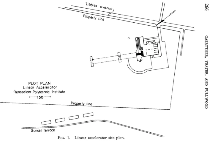
RPI LINAC FACILITY 265 of sufficient space (or for later expansion of space) and flexibility to accommodate a variety of other work. Figure 1 shows a plan of the building and the accelerator site. I t shows' the linear accelerator i n its long and narrow room connecting wit h a large target area in which experiments wil l be conducted. Also shown are two neutron drif t tubes wit h time of flight detector stations indicated at 50 and 100 meters, wit h provision for extending both of these flight paths to 270 meters. Indicated also is the heavy shielding between the accelerator and target rooms and the rest of the building. N o te parti- cularly the arrangement which permits erection of tight radiation barriers between accelerator and target room and between target room and detector stations or indeed between the two halves of the target room.
T h i s site is located on a ridge to the east of the campus at an elevation of 480 ft above the H u d s on River which is at sea level.
Figure 2 is an aerial view of the building showing the m e t h od of construction. T he Linac and target areas are covered wit h earth to a depth of 15 ft. T he cleared area to the left extends out to 100 meters and is r i m m ed wit h an earth wall to reduce the radiation to satisfac- toril y low levels at the property lines.
Figures 3 and 4 further illustrate the laboratory arrangement. Figure 3 is a plan view of the laboratory showing again the accelerator and target rooms and the heavy shielding walls separating this area from the rest of the laboratory. R u n n i ng parallel to the accelerator room is the modulator room in which are housed the klystrons which supply microwave power to the accelerator.
T h i s area is separated by 12 ft of concrete and rock from t he accelerator, thus permitting the inspection of the electronics and cooling system during operation. Also shown in this figure are the control room, the hot cell, and the neutron drift tubes.
Figure 4 shows the view from the target room looking toward the accelerator room.
T a b le I is a list of the significant parameters of the Linac. It operates at L band (1300 Mc/sec) and is powered by 9 Litto n 3250 klystrons, each of which is rated at 1 0 - Mw peak power and 15-kw average power. For utmost reliability, we wil l initiall y operate t h em at 5 M w , 10 kw to achieve the rated 48 kw of average beam power.
T he decision to operate at L band instead of the commonly used S band (3000 Mc/sec) was based on several considerations: (1) W h e re
266 GAERTTNER, YEATER, AND FULLWOOD
FIG. 1. Linear accelerator site plan.
RPI LINAC FACILITY 267
FIG. 2. Aerial view of Linac site.
FIG. 3. Linac laboratory plan.
268 GAERTTNER, YEATER, AND FULLWOOD
FIG. 4. View from target room into accelerator room. Electron drift tube system in foreground as
connects to accelerator inside accelerator room. ^°
RPI LINAC FACILITY 269
270 GAERTTNER, YEATER, AND FULL WOOD T A B L E I
BASIC PARAMETERS OF THE RPI L I N A C
1. RF frequency L band (1300 Mc/sec)
2. RF amplifiers Klystron—Litton-3250
3. Rated RF output of L-3250 10-Mw peak 15-kw average 4. Number of accelerating sections 9
5. Length of sections 3 ft
6. Accelerating waveguide Traveling wave T M
0 1
, λ/47. Shunt impedance 12.0 Χ 10
6
ohms/ft8. Attenuation constant 0.12 neper/ft
9. Rated electron energy 35 Mev
10. Rated peak electron current 0.8 amp 11. Rated average electron power 48 kw
12. Pulse duration 0.1,0.3, 1.0, 2.0,4.5/xsec
13. Repetition rates 7.5, 15, 30, 60, 120, 180, 240,
... 720 pulses/sec
14. Beam size 2 cm diameter
15. Angular divergence of beam 10~
3
radians, total anglehigh peak currents are desired, the lower frequency is definitely indicated (most pulsed neutron experiments depend strongly on high peak neutron yield rather than average). (2) Higher power klystrons were available at L band than S band to compensate for the lower shunt impedance of the L band accelerating guides.
(3) T he pulse-shortening problem in S band machines had not been solved at that t i m e .
2
Other advantages of L band are a larger guide aperture, and higher electron trapping efficiency. T he chief advan- tage of S band would be the shorter filling time which makes it possible to utilize a larger fraction of the RF pulse for electron acceleration. I n summary, for this new type of high powered accelera- tor L band is preferable, although S band is probably better when the goal is the highest possible electron energy.T h e re are other factors which are significant to accelerator operation; several of these can be quickly enumerated. T he m a x i m um trapping efficiency, i.e., the ratio of the o u t p ut current to the input current, is about 8 0 %. T h is is achieved by a buncher immediately after the injector. T he injector is designed for operation to 200 kv and is capable of injecting 5-amp pulses of c u r r e n t; so far it has not been tested to full voltage b ut it has already operated at 120 kv.
T he v a c u um stations are of unique design and packaging. T h ey
RPI LINAC FACILITY 271 consist of a mechanical forepump and a water-cooled oil diffusion p u mp and the use of activated copper traps. T h ey are connected through shut-off valves which, lik e all the rest of the machine, use no organic gaskets, only copper; this permits the baking-out of the whole machine or any part of it. T o this end, the accelerating guide magnets are glass cloth insulated in order to withstand the temperatu- res. Typical pressures during operation range from low on the 1 0
-6
mm Hg scale on down to 1 0-8
m m. T h is I think is unique in accelerators without t he use of refrigerated traps. T h e re are 9 t e m- perature regulating packages, one for each guide, which regulate the temperature of the guides to better than z t i ° C . T he guides are brought up to temperature by means of electric heaters so that the guides are ready to go in 30 min, which is also the w a r m - up time on the klystrons. T h e re is an elaborate system of interlocks for the protection of both personnel and equipment.A few additional statistics are: T he stored energy in the capacitors i n the 9 modulators is 640 joules. T he average power input during full power operation is about 1 M w . T he physical length of the accel- erator from the injector to the quick acting pneumatic valve is 53.5 ft and the length of the electrom beam drift tube is 73.5 ft.
Figure 5 is a block diagram of the electrical system of the Linac. T he sequence begins wit h the microwave master oscillator, which is a triode oscillating at 1300 M c ; after the intermediary of triode and tetrode amplifiers about 5 kw is delivered to the input of each klystron.
T h i s is sufficient to drive these 3-cavity klystrons which have a power gain of 35 db. T he phasing of each klystron and the buncher is by means of remote control operation of " t r o m b o n e" type phase shifters.
I t should be mentioned in passing that all normal adjustments of the accelerator can be done in the control room. T he microwave power leaves the klystrons, travels t h r o u gh rectangular guides pres- surized wit h freon, t h r o u gh ceramic windows into the high v a c u um of t he accelerator. I t is t h en coupled into the traveling wave type accelerating guides where it delivers its power to the electron beam.
T h at power which is not absorbed is coupled out into water-cooled d u m my loads. Just prior to the d u m my load, a probe is located.
T h i s signal is very useful for adjusting the accelerator since it indica- tes the beam loading, i.e., it indicates how well that section is ad- justed. T he voltage standing wave ratio in the waveguide system is less than 1.3.
Figure 6 is a schematic of the mechanical arrangement of the
TUNING CONTROL
DUMMY LOAD
DUMMY
LOAD DUMMY
LOAD
OUTPUT""^
BEAM
D.C.
SUPPLY ELECTRON!
GUN
H.V.
" INSULATION PULSE COUPLING
il î FOCUS MAGNET
R.F.
BUNCHER!
CAVITY
CONTROL GRID PULSER
FOCUS MAGNET
BEAM STEERING I
COILS
PHASE SHIFTER
INJECTOR CONTROL PANEL
DRIVER CONTROL
PANEL
CONTROL P A N E L
KLYSTRON DRIVER AMR a OSC.
ILL WAVE GUIDE
COMPOUND]
COUPLER
KLYSTRON AMP.
POWER DIVIDER
MASTER TRIGGER GENERATOR
DRIVER PULSER
ÎCOM POUND) COUPLER
9
!bWAVE- GUIDE SECTION
OUTPUT COUPLER
BEAM ANALYZERI
BEAM DIFFUSER
OUTPUT.
WINDOW
KLYSTRON AMP.
FIG. 5. Block diagram of Linac electrical system.
272 GAERTTNER, YEATER, AND FULLWOOD
RPI LINAC FACILITY 273
FIG. 6. Accelerator mechanical layout.
274 GAERTTNER, YEATER, AND FULLWOOD
Linac. I t shows the nine waveguide sections and the 200-kv Cockcroft-Walton injector. T he RF couplers to the waveguides are indicated and also some of the d u m my loads.
A schematic of the microwave system is shown in Fig. 7 ; included are the pulsed electron gun, focusing coils, the buncher cavity wit h tuner, the waveguide feed from the klystrons, and the o u t p ut to the d u m my loads.
T he beam analyzer capable of operation from 4 to 70 M ev and absorbing power of 35 kw is shown in Fig. 8. I n the background is seen the accelerator prior to connecting the waveguides.
Figure 9 is a view of one of the accelerating sections. I t shows a waveguide enclosed in the focusing coils. T he pipes on each end are used for transferring the water from the temperature regulat- ing packages. Some additional details are shown in Fig. 10 and 11.
Figure 10 shows the buncher, and to the extreme left where the blank-off plate is located, the electron gun is mounted. I n the back- ground, housed in the square box, is located the motor that adjusts the buncher cavity tuning. Figure 11 shows the water-cooled electron beam exit window. I t absorbs slightly over 1 % of the beam power.
T o the left is seen a pneumatically operated valve used for protecting the accelerator in the event of failure of the electron beam window.
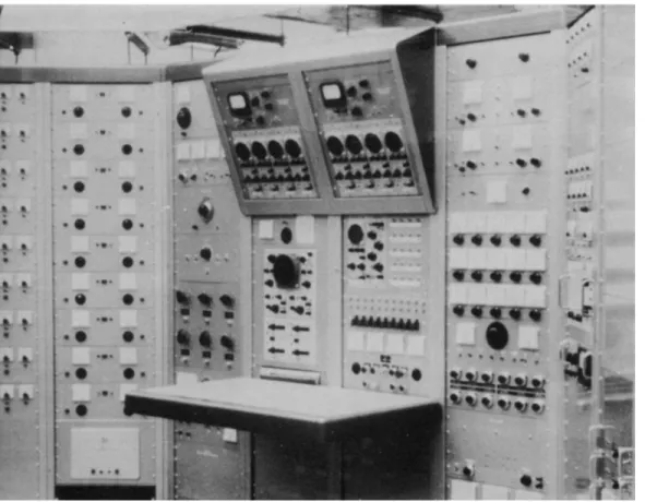
Figure 12 shows the control console. T he main oscilloscope is a dual beam type wit h independent time bases on each beam. T he over-head blister holds the 2 bolometers and 8 of the 9 oscilloscopes used for monitoring the beam loading of each guide.
Figure 13 shows the row of klystrons m o u n t ed on their pulse transformers as they appeared prior to shipping to Troy. T h ey are now housed in a shielded room in order to keep the electrical inter- ference as low as possible. T he boxes on the side of each klystron are made of lead and are installed for personnel protection.
T he energy-current relationship for a current loaded waveguide is shown in T a b le II . T he values of energy calculated for various values of peak RF power are shown. V
0
is the m a x i m um energy correspond- ing to zero current. Ve
is the energy at m a x i m um efficiency; this occurs at one-half the energy for zero current. Vi
is the energy cor- responding to our design figure of 0.8 amp. T he energy values have checked out quite accurately so far, for a peak RF energy of 5 M w per section.Some of the results obtained during the demonstration test program at Walnut Creek are summarized in Table I I I . T h e re is one measure-
RPI LINAC FACILITY 275
FIG. 7. Microwave guide plan of Linac.
FIG. 8. Beam analyzer mounted at accelerator output. In right foreground is lead enclosed Faraday cup attached to vacuum chamber which is between poles of deflecting magnet.
276 GAERTTNER, YEATER, AND FULLWOOD
RPI LINAC FACILITY 277
Accelerating section encased in focusing coil ; R F window assembly is at right.
278 GAERTTNER, YEATER, AND FULLWOOD
•UOU09S SuUBJ9pDDB
JSJI J 9ψ pUB JO)33[UI
9ψ U99M}9q
p9^B0O| 'J9ipun q UOJÏ09[
g 'Q I 'OI
^
RPI LINAC FACILITY 279
FIG. 11. Electron beam exit window assembly shown in place at output of accelerator. Structure at the left is fast acting valve to seal waveguide in case of window leakage.
FIG. 12. Accelerator control console.
280 GAERTTNER, YEATER, AND FULLWOOD
FIG. 13. Klystron array. Each klystron is mounted in a cabinet which contains an oil-filled high voltage pulse transformer, and the klystron structure is encased in lead for absorption of X-rays generated in the collector.
RPI LINAC FACILITY 281
282 GAERTTNER, YEATER, AND FULLWOOD
E
0
= Λ/2ΡΤΊwhere V — Electron energy, Mev
E
0
= Maximum voltage gradient, volts/ft L = Length, ft = 3 ft/ = Attenuation constant, Neper/ft = 0 , 1 2 r = Shunt impedance, ohms/ft — 1 2 . 0 Χ 1 0
6
/ = Electron current, ampsΡ = Peak power, watts
V
0
= Electron energy at zero currentVi = Electron energy at i = 0 . 8 0 amp v
e
= Electron energy at maximum efficiencyElectron current at maximum efficiency
Ρ E
0
V0
le ve
ViMegawatt millivolt/ft Mev amp Mev Mev
5 3 . 7 9 9 . 5 5 0 . 8 2 4 . 7 8 4 . 9 2
6 4 . 1 6 1 0 . 4 7 0 . 9 0 5 . 2 4 5 . 8 4
7 4 . 4 8 1 1 . 3 0 0 . 9 7 5 . 7 8 6 . 6 7
8 4 . 8 0 1 2 . 1 0 1 . 0 4 6 . 0 5 7 . 4 7
9 5 . 0 9 1 2 . 8 2 1 . 1 1 6 . 4 1 8 . 1 9
1 0 5 . 3 7 1 3 . 5 3 1 . 1 7 6 . 7 7 8 . 9 0
a
For nine sections: V0
(max), 1 2 2 Mev @ 0 current; Ve
(max), 6 1 Mev @ 1 . 1 7 amp; V{
(max), 8 0 Mev @ 0 . 8 amp.ment at 4.5-/xsec beam pulse width and a repetition rate of 60 pulses/
sec, and one for 0.1 /xsec. T he RF power per section was 5 - Mw peak and about 1.8 kw average for 6-jusec RF pulses. Values are shown for the nine sections. T he corresponding efficiencies are calculated to be 7 6% based on the peak values and 5 3% based on average values. For the 0.1 /usee pulses the RF drive was unchanged. One measurement gave 50 M ev wit h 1.5-amp peak beam current, i.e., 7 5 - Mw peak. T h is is an example of the utilization of stored energy in the guide for short pulses—one of the favorable characteristics of the L - b a nd guide.
T A B L E II
ENERGY-CURRENT RELATIONSHIP FOR O N E 3 - F T ACCELERATING SECTION*
RPI LINAC FACILITY 283 T A B L E I I I
INITIAL T E S T PERFORMANCE OF ACCELERATOR
4.5-psec electron pulses — 60 pps R F (per section):
5 - M w peak, 1.8 kw average, 6 /usee [ 4 5 Mw, 1 6 kw for 9 sections]
Beam:
1 9 8 /Lta average, 4 3 Mev, 0 . 8 amp peak 3 4 M w peak, 8 . 5 kw average efficiency (peak) 3 4 / 4 5 = 7 6 % efficiency (ave) 8 . 5 / 1 6 = 5 3 %
0.1-μsec electron pulses — 60 pps R F (per section):
same as above Beam:
5 0 Mev 1.5 amp (peak) == 7 5 M w (peak)
T he expected neutron production rates in u r a n i um are 2 Χ 1 0
14
neutrons/sec average wit h a peak production rate of 3 Χ 1 017
neutrons/sec. I t is difficul t at this point to determine how m u ch the peak production rate can be increased. However the peak beam output could probably be increased to 100 M w by increasing the peak current from the gun, and the RF power can be increased to 10-MwFIG. 1 4 . Output electron current as a function of time during 4.5-ftsec pulse. 1.0 /xsec/cm; 2 0 0 ma/cm; 4 2 Mev.
284 GAERTTNER, YEATER, AND FULLWOOD
peak. T h e se factors would result in about a threefold increase to about 1 0
18
neutrons/sec production rate during the pulse.Figure 14 shows an oscillograph trace of a 4.5-/xsec beam pulse.
T he peak value is about 0.8 amp. T he clean, square shape is typical of what can be done wit h proper adjustment. T he picture is not a single trace but is about a 1-sec exposure, and it is significant that the pulse-to-pulse jitter is too small to be seen; the jitter must be less than 2 %.
A n oscilloscope trace of a 0.1 -/xsec beam pulse is shown in Fig. 15.
FIG. 1 5 . One-tenth microsecond beam pulse. 1 . 0 2 0 ftsec/cm; 1 9 4 ma/cm;
5 5 Mev.
T he apparent rise-time, about 20 nsec, is not a true indication because of oscilloscope and cable limitations; the actual rise-time is estimated to be 10 nsec.
Figure 16 shows the electron beam energy spectrum measured for a 4.5-/xsec pulse. T he full width at half-maximum is about 6 %; it is believed that adjustments can be made to improve this, but probably this can be regarded as typical of routine operation.
I n order to make use of the accelerator it is, of course, necessary to direct the electrons from the output of the accelerator to experimen- tal stations. Figure 17 shows the electron beam drift tube system designed for this purpose. T h is arrangement wil l accommodate two experiments without the need of dismantling the setups. On the left is shown the deflecting magnet and 1% slit system for energy measurements at average power levels up to 35 kw. On the extreme left is located a quick acting pneumatic valve. F r om left to right is
RPI LINAC FACILITY 285 seen the quadrupole pair, one on each side of the shielding wall, another quick acting valve, then the beam locating device. Item N o. 11 is a remotely controlled 2-kw Faraday c u p; a beam exit window would be in this location if this station (No. 1) were in use
40
36 38 40 42 44 46 48 50 52 54 56
FIG. 1 6 . Electron energy spectrum of accelerator beam. Pulse width, 4 . 5 /xsec.
in an experiment. If this station is not in use, the window is removed and other section of drift tube is inserted. Al l drift tubes are double walled wit h water cooling in the interspace. T h ey are wrapped with Conetic metal to shield against the earth's field. T he copper gasket seal on the ends of a drift tube is compressed by a ring which can be quickly removed in case of high residual radiation.
I n order to utilize the full 48-kw o u t p ut of the machine, special target designs are necessary. Figure 18 shows our first attempt at a converter for high power operation. It consists of a water-cooled tungsten ring which is rotated at several h u n d r ed rpm. T he window rotates with the ring in this design. T he tungsten is primarily an (e, γ) converter. It is backed up by a series of water-cooled plates, which may be tungsten or uranium, for (y, n) conversion.
I n conclusion I would lik e to express my appreciation to the many people who have made this project possible. T he project would not
SIDE VIEW
FIG. 1 7 . Diagram of electron beam drift tube system; some of these details were visible in the photograph of Fig. 4 .
286 GAERTTNER, YEATER, AND FULLWOOD
RPI LINAC FACILITY 287
FIG. 18. Rotating target assembly.
288 GAERTTNER, YEATER, AND FULLWOOD
have been possible without the support of the A E C; in particular without the encouragement and backing of Ir a Zartman, who is here today as Chairman of this session. We have had very fine coopera- tion from A R C O. A nd finally I would lik e to thank the administra- tion of RPI for their excellent cooperation in helping to establish this facility on this campus.
REFERENCES
1. L. Katz, Desirable linear electron accelerator characteristics for Nuclear Research, Nuclear Instr. & Methods 2, 14 (1961).
2. J. C. Nygard and R. F. Post, Recent advances in high power electron accelerators for physics research, Nuclear Instr. & Methods 2, 126 (1961).