Obuda University
PhD Thesis
Drive Control Optimization of Walker Robots Using Dynamic Simulation Model
by Istvan Kecskes
Supervisor:
Dr. Peter Odry, College Professor
Applied Informatics and Applied Mathematics Doctoral School
Budapest, 2018
Members of the Defense Committee:
Members of the Comprehensive Examination Committee:
Date of the Defense:
Abstract
The high-quality energy-efficient regulation of electromechanical systems is an important chal- lenge for today’s robot technology development. The construction of the dynamic simulation model is indispensable to the optimization of robot driving controlling, because such a model estimate adequately the robot’s behavior. The main aspects of the controlling’s quality can be defined as: fast, energy efficient, battery saver, and ensure vibration-free walking for the robot.
The Szabad(ka)-II hexapod robot with 18 DOF embedded mechatronic devices is suitable for complex drive control research. My goals also included achieving robustness concerning robot, environmental and controller parameters since the mechanical and electronic inaccuracy of the device is not negligible.
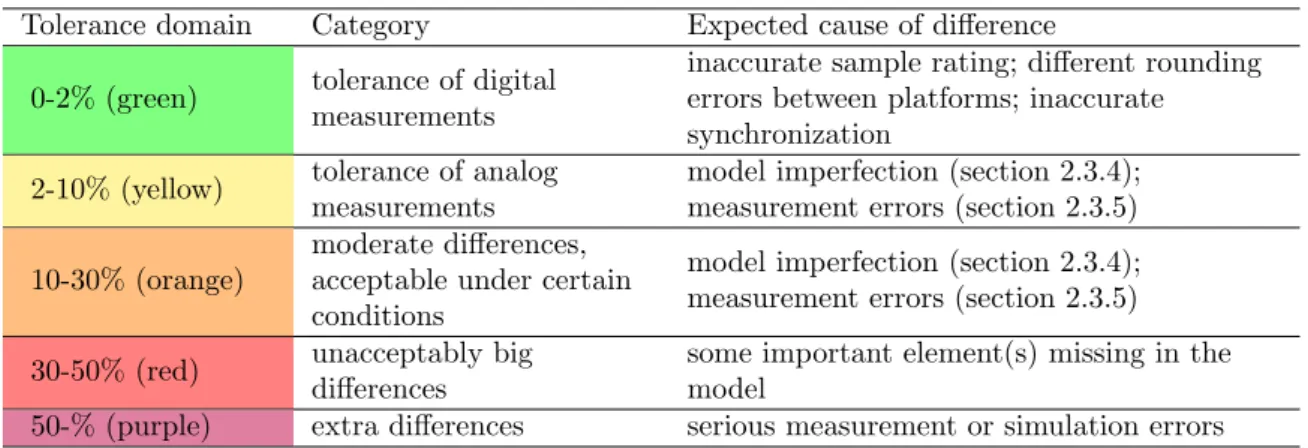
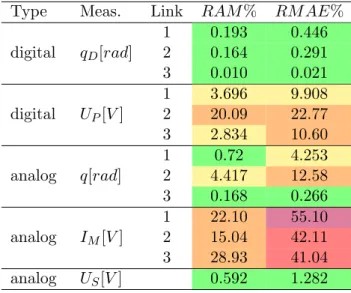
Model validation: During the verification and validation of the simulation model, I evaluated whether the results of the simulation correspond to the real system. The validation procedure was performed twice, first before the development and optimization of the drive control, then afterwards, using a selected optimal controller. The former was necessary to develop the optimal drive control using a realistic model. The latter was required to prove that the goal had been achieved. For the classification of the validation results, the tolerances and expected error limits were defined based on the measurement and estimation of system accuracy. During validation, the motor current showed a significant difference, therefore this issue was discussed in detail.
Determining the main steps of the robot model validation and the numerical and qualitative grading of the differences are the main scientific results.
Optimizer algorithm: Since the simulation tasks to be run were rather time-consuming, the efficiency of the optimization algorithm had become a key issue. Algorithms able to find the op- timum with the lowest number of function calls for multi-variable, non-continuous, non-linear, mixed-integer problems were used. Heuristic search methods were tested against each other on quick test functions which incorporate properties similar to those of a robotic simulation problem. The best results were achieved by the particle swarm optimization method (PSO), the implementation of which had been paralleled. A new and widely usable method was created to select the most appropriate optimization search method.
Robust Multi-Objective Multi-Scenario Optimization: In general, quality motor control needs respond to a number of requirements (such as low power consumption, accuracy, speed, battery saving), so the system is multi-objective. The simulation model includes environmental or mission parameters that are not part of the parameters to be optimized but their variation creates different scenarios. A multi-scenario simulation can be created with the typical values of these parameters where the optimum is searched for all scenarios at the same time. Such optimum is more robust than one achieved through a process using separate scenarios since the intended use of the robot is represented by the multi-scenarios.
Fuzzy Logic Motor Controller: A fuzzy-PI motor controller that can be embedded in the processor of real robot was developed and optimized using the simulation model. A lookup table-type solution for the real time operation of the fuzzy controller suitable in the low power
microcontrollers was developed. The feedback of the motor current to the fuzzy controller al- lowed the option of providing control characteristics that avoid high current-torque fluctuations.
This ensures a softer control behavior or, in extreme cases, inverse directional control, which can better protect the electromechanic parts and the batteries. This control behavior can be easily implemented using fuzzy descriptive (linguistic) rules. By measuring the quality of the motor controller, it was checked that the elaborated fuzzy-based control provided better quality and robustness compared to the classic PID control.
In case of the Szabad(ka)-II robot, the presented drive optimization achieve 27% faster locomo- tion and 10% less power consumption compared to an earlier, non-optimized program.
Keywords: Hexapod Robot, Dynamic Model, Fuzzy Logic Control, Robust Optimization, Multi- Objective Optimization
Abstract
Az elektromechanikai rendszerek min˝os´egi energia-hat´ekony szab´alyz´asa a mai robot technol´ogiai fejl˝od´es egyik fontos kih´ıv´asa. A szimul´aci´os dinamikai modell meg´ep´ıt´ese elengedhetetlen, hiszen a robot hajt´as szab´alyz´ast egy olyan m´odszerrel lehet optimaliz´alni, amely j´ol meg- becs¨ulni a robot viselked´es´et. A min˝os´egi szab´alyz´as f˝o szempontjai ´ıgy hat´arozhat´o meg:
gyors, energia-hat´ekony, akkumul´ator k´ım´el˝o, r´azk´od´as-mentes j´ar´ast biztos´ıt a robotnak. A Szabad(ka)-II hatl´ab´u robot, 18 szabads´agfokos be´agyazott mechatronikai eszk¨oz, alkalmas
¨
osszetett hajt´as szab´alyoz´asi feladatok kutat´as´ara. Emellett a robot- a k¨ornyezet- ´es a szab´alyz´o- param´eterekkel szembeni robusztuss´ag is a kutat´asom c´eljai k¨oz´e tartozik, mivel az eszk¨oz mechanikai ´es elektronikai pontatlans´aga nem elhanyagolhat´o.
Modell valid´al´as: A szimul´aci´o modell verifik´al´asa ´es valid´al´asa alatt felm´ertem, hogy a szimul´aci´o eredm´enyei megfelelnek-e a val´os rendszernek. A valid´aci´os elj´ar´ast k´etszer lett elv´egezve, el˝osz¨or a hajt´as-szab´alyoz´as fejleszt´ese ´es optimaliz´al´asa el˝ott, majd az ut´an, egy kiv´alasztott optim´alis szab´alyz´oval. Az els˝ore az´ert volt sz¨uks´eg hogy egy val´os´agh˝u modellen keress¨uk az optim´alis szab´alyz´ast. A m´asodik pedig igazolja, hogy val´oban megval´os´ıtottam- e a kit˝uz¨ott c´elt. A valid´al´as eredm´enyek klasszifik´aci´oj´ahoz meghat´aroztam a toleranci´akat illetve v´arhat´o hibahat´arokat a rendszer pontoss´ag´anak a kim´er´ese ´es becsl´ese alapj´an. A valid´aci´o sor´an a motor ´arama l´enyeges elt´er´est mutatott, ez´ert r´eszletesen foglalkoztam ezzel a k´erd´esk¨orrel. A robot modell valid´al´as f˝o l´ep´eseinek meghat´aroz´asa ´es az elt´er´esek sz´amszer˝u
´
es min˝os´egi oszt´alyoz´asa a f˝o tudom´anyos eredm´enyek.
Optimaliz´al´o algoritmus: Mivel id˝oig´enyes szimul´aci´os feladatokat kell futtatni az opti- maliz´al´o algoritmus hat´ekonys´aga kulcsk´erd´ess´e v´alt. Olyan algoritmusok lettek kiv´alasztva, amelyek a legkevesebb f¨uggv´enyh´ıv´assal k´epesek r´atal´alni az optimumra sok-v´altoz´os, nem folytonos, nem-line´aris, vegyes eg´eszsz´am´u probl´ema eset´en. Heurisztikus m´odszereket versenyeztet- tem gyors tesztf¨uggv´enyeken, amelyekbe ilyen hasonl´o tulajdons´agok lettek be´ep´ıtve, mint ami a robot szimul´aci´ora is jellemz˝o. A r´eszecskeraj m´odszert (PSO) ´erte el a legjobb eredm´enyt, amelynek implement´aci´oj´at p´arhuzamos´ıtottam. Egy ´uj ´es sz´elesk¨orben alkalmazhat´o m´odszert kaptam a legjobb optimaliz´aci´os keres˝o algoritmus meghat´aroz´as´ara.
Robusztus t¨obbc´el´u t¨obbszcen´ari´os optimaliz´al´as: ´Altal´aban a min˝os´egi szab´alyz´as t¨obb szempontnak is meg kell, hogy feleljen (p´eld´aul kis fogyaszt´as, pontoss´ag, gyorsas´ag, akku- mul´ator k´ım´el´es), ez´ert a rendszer t¨obb-c´el´u (multi-objekt´ıv). A szimul´aci´os modell tartal- maz olyan k¨ornyezeti vagy k¨uldet´esi param´etereket, amelyek nem tartoznak az optimaliz´aland´o param´eterekhez, de ezek v´altoz´asa k¨ul¨onf´ele szcen´ari´ot k´epez. Ezen param´eterek tipikus ´ert´ekeivel egy t¨obb-szcen´ari´os szimul´aci´ot lehet l´etrehozni, ahol az optimum egyszerre minden szcen´ari´ora van keresve. Az ilyen optimum robusztusabb mint ha csak egy szcen´ari´ora lenne keresve a megold´as, hiszen a robot rendeltet´esszer˝u haszn´alat´at a kiv´alasztott t¨obb szcen´ari´o reprezent´alja.
Fuzzy-alap´u motorszab´alyz´as: A szimul´aci´os modellez´es seg´ıts´eg´evel fejlesztettem ´es opti- maliz´altam egy fuzzy-PI motor szab´alyz´ot, amely be´agyazhat´o a val´os robotba. A kis tel- jes´ıtm´eny˝u mikrovez´erl˝oknek megfelel˝o keres˝o t´abl´as megold´ast fejlesztettem ki a fuzzy szab´alyz´o val´os idej˝u fut´as´ahoz. A motor ´aram´anak visszacsatol´asa a fuzzy szab´alyz´oba lehet˝os´eget k´ın´alt,
hogy olyan szab´alyz´asi jelleget biztos´ıtsak, amely ker¨uli a nagy ´aram-nyomat´ek ingadoz´asokat.
Evvel egy puh´abb vagy extr´em esetben inverz ir´any´u szab´alyz´asi jelleg kaphat´o, amely jobban v´edi az elektromechanik´at, valamint az akkumul´atorokat. A fuzzy le´ır´o szab´alyaival k¨onnyen lehet ezt a viselked´est implement´alni. A szab´alyoz´as min˝os´eg´enek m´er´es´evel ellen˝orizve lett, hogy a kidolgozott fuzzy alap´u ir´any´ıt´as jobb min˝os´eget ´es robusztuss´agot mutat a klasszikus PID-hez k´epest.
Szabad(ka)-II robot eset´en a bemutatott hajt´as optimaliz´al´as 27%-kal gyorsabb ´es 10%-kal kisebb energiafogyaszt´ast tudott el´erni egy kor´abbi nem optimaliz´alt programhoz k´epest.
Acknowledgement
First and foremost, I would like to thank my loving Creator for making me a curious being who loves to explore His creation and for giving me the opportunity to do this research.
I would like to express the appreciation to my research supervisor Dr. Odry P´eter. With- out his guidance and persistent help this dissertation would not have been possible.
I would also like to show gratitude to my committee, including Prof. Dr. Rudas Imre, Prof.
Dr. Horv´ath L´aszl´o, Dr. V´amossy Zolt´an, Dr. Galambos P´eter and Dr. Pletl Szilveszter. I must also thank to head of my doctoral school, Prof. Dr. Gal´antai Aur´el.
I thank Cambridge University Press for permission to include Chapter 2 of my dissertation, which was originally published in Robotica Journal.
I would also like to thank the University of Dunaujvaros for their financial support granted through the predoctoral fellowship. This work is supported by the EFOP-3.6.1-16-2016-00003 project. The project is co-financed by the European Union.
To my family: you should know that your support and encouragement is worth more than I can express it on paper.
Contents
1 Introduction 1
1.1 Research Background . . . 1
1.2 Research Objectives . . . 2
1.3 Document Overview . . . 2
1.4 Szabad(ka)-II Hexapod Robot . . . 3
2 Simulation Modeling 10 2.1 Simulation and validation at other hexapods . . . 10
2.2 Szabad(ka)-II Simulation Model . . . 12
2.3 Model Validation . . . 20
2.4 Comparison of Results and Interpretation of Differences . . . 27
2.5 Discussion and Conclusion . . . 41
2.6 Theses Summary . . . 44
3 Optimization Methods for Trajectory and Motor Controller 47 3.1 Introduction . . . 47
3.2 Selection of Optimization Methods . . . 50
3.3 Fuzzy-PI Controller . . . 54
3.4 Results and Comparison . . . 59
3.5 Discussion and Conclusion . . . 60
3.6 Theses Summary . . . 62
4 Multi-scenario Multi-objective Optimization of Fuzzy-PI Motor Controller 64 4.1 Introduction . . . 64
4.2 Multi-scenario Multi-objective Optimization . . . 64
4.3 Fuzzy-PI Motor Controller . . . 68
4.4 Results . . . 71
4.5 Discussion . . . 74
4.6 Theses Summary . . . 75
5 Embedding Optimized Trajectory and Motor Controller 77 5.1 Introduction . . . 77
5.2 Software Architecture . . . 78
5.3 Fuzzy-PI Motor Controller Implementation . . . 80
5.4 Comparison Results of Original and Optimized Driving . . . 82
5.5 Discussion and Conclusion . . . 84
5.6 Theses Summary . . . 85
6 Conclusion 87
References 89 .1 Appendix: Comparison of Szabad(ka)-II with similar robots . . . 98 .2 Appendix: Details of Szabad(ka)-II Dynamic Model . . . 100
1 Introduction
1.1 Research Background
Many universities, research centers and companies have been researching and developing robots since the 1970s, although most of them are laboratory prototypes. Generally, the incoming robots have a number of shortcomings, so there is still no widespread use in the industry: they are slow and not energy-efficient, which would be important for a mobile robot De Santoset al.
(2007).
Energy efficient walker robot development focuses primarily on energy efficient motor drive and optimal robot’s structure. Various energy-efficient approaches have been studied for multi- legged robots, where they research to minimize electrical energy by optimizing the structural parameters of the locomotion de Santoset al. (2009). A complete dynamic model is important for the development of walker robots and its energy efficient optimization processes: Dynamic stability was researched by four legged walker robots with different legs and gaits Lin and Song (2001); neural network-controlled walker robot were optimized using a simulation model Von Twickelet al.(2012); or the size of actuators are defined using dynamic model of six-legged robot Carbone and Ceccarelli (2008a).
Fuzzy control of six-legged walker robots is a widespread solution that has been developed in last 20 years. For example, Pratiharet al. (2000) optimized a fuzzy-based walk controller with a genetic algorithm. Besides walker robots - such as Sakr and Petriu (2007), fuzzy controller are also used for crawling robots too Wanget al. (2009). Robust controlling requirements can be met by fuzzy solutions Tanakaet al. (1996). Fuzzy systems show benefit from the classical, commonly used PID controllers Kecsk´es and Odry (2014). Fuzzy controllers have the ability to comply robustly, i.e. they can produce better results in extreme conditions Kecsk´es et al.
(2017a). The fuzzy controller can be advantageous compared to other complex controllers, considering the resource requirement Kecsk´es et al. (2015a). The advantages of fuzzy control are outstanding in complex, more freedom structures (robots, especially mobile robots), because the deduction of model-based controllers are cumbersome task to such robots.
The general definition of the quality of the 4, 6 and 8 legged walkers was not dealt with in detail. The energy efficiency and speed are the two main quality aspects, but the other aspects are usually explored in independently, such as vibration and self-defense mechanisms. Exam- ining preferences between different quality aspects and Pareto solutions are future challenge in research of walker robots. This dissertation was initiated to following this direction and its main new scientific result relates to the definition of walking quality.
The Szabad(ka)-II hexapod robot with 3 degree of freedom per leg is an embedded mecha- tronic system suitable for complex drive control tasks. Using a simulation model the robot’s behavior in different applications can estimate, even in extreme cases: energy-efficient, vibration free, or battery-saver drive controls can be developing. The behavior of the robot can be evalu- ated in extreme cases, which is important because the protection against structural damage is also included in the task of motor control.
1.2 Research Objectives
The main aim is to develop a motor control process based on an effective fuzzy controller that is capable of controlling systems with a nonlinear dynamics and strong parameter uncertainty.
During the research, mechatronic tools are needed to embed, test, and validate the developed procedures I have. The Szabad(ka)-II robot is such a device, described in next section 1.4.
Research objectives are follows:
• Build the complete mechatronic simulation model of the robot / manipulator. An elec- tronically and dynamically realistic model, i.e. the embedded electric control, electric motors, robot body and ground dynamics are all part of the model. Realistic, that is sufficiently precise according to measurement errors. It is required to compare the results generated by the robot / manipulator and the simulation model, and then interpret the differences. If one of the variables differs more than the expected tolerance, then the reasons and explanations must be sought.
• It should look for the appropriate, but inexpensive, sensor surface that is needed for robot walking and drive control. Three dimensional digital accelerometer and gyroscope mounted on robots can be used well in model validation and gait / walking tracking.
In addition to angular velocity encoders, the current of each drive motor can also be measured, which can be an important input of the fuzzy controller. The measurement of the power supply is also useful for validating the model.
• Define the drive quality metrics (objective functions) that can be used to achieve the de- sired behavior and quantify the robot’s walking quality. Longer-term research purpose is to determine the preference between the objective functions so that the quality measure- ment will be appropriate for the various applications of the robot. This assumes that the desired utility function, which aggregate the multi-objective quality based on preference, and the drive optimum are sufficiently robust.
• It is necessary to define the gaits or walking tasks (scenarios) where the quality measure- ment should be carried out, taking into account the objectives and the capabilities of the robot. It need to choose scenarios that can be carried out in the simulation and in reality in the given laboratory conditions.
• It should look for the optimal quality drive control according to the selected objective functions, which includes the parameters of leg trajectory curve and fuzzy-based controller.
Optimization on the simulation model should be run simultaneously on all the specified scenarios.
• The validation of the obtained drive optimum should be performed. For this, the optimal controller and trajectory must be embedded in the robot and the measurements should be made.
1.3 Document Overview
The dissertation is structured as follows.
• Chapter 1.4: Introduces the development objectives and motivations of the Szabad(ka)-II hexapod robot. Describes the basic structural elements of the robot, and compares it to another similar hexapod robots. Its content has been published in Kecsk´eset al.(2015b).
• Chapter 2: The realistic dynamic model is an essential element of the computational optimization. First, the dissertation describes the simulation model and its validation procedure. The measurements on the real robot are compared to the simulation results in the validation procedure. A genetic algorithm is used to define the immeasurable parameters in the model calibration tasks. Its content has been published in Kecsk´es et al. (2015b).
• Chapter 3: The motor controllers are developed and optimized using the validated simu- lation model. The fuzzy logic–based motor controller takes the error of joint angles and the absolute motor current as the inputs, and produces proportional voltage output. This chapter describes the selection of the global optimizer algorithm, and the design vari- able definition related to the motor controller and trajectory curve. Its content has been published in Kecsk´es and Odry (2014).
• Chapter 4: The quality definition and quantification of the hexapod robot’s walking are analyzed as a multi-objective problem. The multi-objectives are aggregated into a scalar fitness value using preference weights. The multi-scenario simulation approach in applied to find the optimum for the intended use of the robot instead of a single scenario. In this chapter, the optimization of a Fuzzy-PI motor controller is described, which can be embedded in the low-cost microcontrollers on the Szabad(ka)-II robot.
• Chapter 5: The optimized motor controller and trajectory curve are implemented into an improved real-time framework of the Szabad(ka)-II robot. The initial and the developed leg-drive systems are compared. Its content has been published in Kecsk´eset al. (2016).
• Chapter 6: The overall conclusions of the previous chapters.
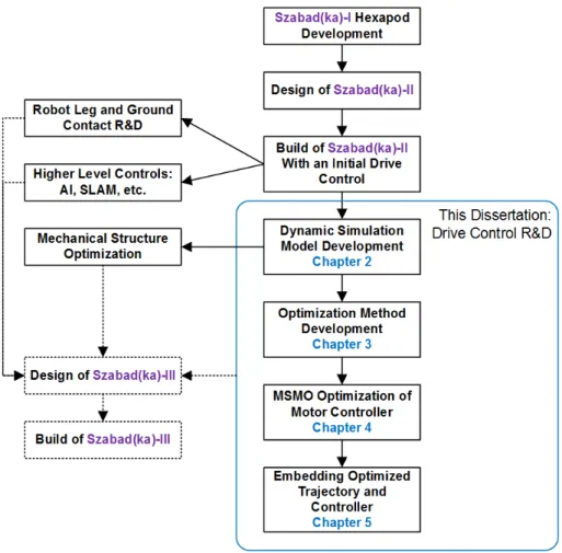
The research and development related to Szabad(ka) hexapod robot series are wider than the scope of this dissertation. The parts of the research shown within the blue rectangle in Fig. 1.1 belong to the scope of the present thesis.
1.4 Szabad(ka)-II Hexapod Robot
Nowadays, due to the continuous development of technology, applications in the field of mobile robotics are becoming increasingly common. Accordingly, researchers show more interest in development of various mobile devices. The simplest mobile robots have wheels, crawlers or a combination of these two. For these robots overcoming even small obstacles is difficult. In contrast to wheeled devices, walker robots have more complex structures in terms of their me- chanical, electrical and software composition, but when properly built they can easily overcome much higher and more complex barriers.
Walker robots can be classified into bipeds, quadrupeds, hexapods, octopods and “cen- tipedes”. With more than two-legged robot structures, it is easier to achieve and maintain
Figure 1.1: This Dissertation and the Szabad(ka) Hexapod Robot Series Research and Development balance and the center of gravity – compared to the size of the robot – can be closer to the ground than in the case of bipeds. With the right walking algorithm three noncollinear legs of the robot are on the ground all the same time. Quadrupeds have a disadvantage over structures with six or more legs namely that if they use a static stable gait then only one leg can be in air at a time, which results in slow walking speed. Using a dynamic stable gait like the trot gait two legs can be lifted at the same time, but in this case it is harder to respond to unforeseen events like obstacle collision.
In case of hexapods, when the fast “tripod” gait is used, there are always three legs on the ground, and three in the air. Therefore, the walking speed of a hexapod robot can be two or three times faster than that of a quadruped robot. In case of octopods, due to the extra two feet, robots can have four feet on the ground and four in the air in the same time, however, there is a disadvantage, because it is difficult to touch the ground with four feet simultaneously. Eight- legged robots have greater weight, power consumption and cost more because of the extra legs.
In Kar (2003), a detailed analysis of walking devices was carried out. This analysis separately dealt with the maximal speed of the robots depending on the number of feet. The publication Silva and Machado (2007) deals with the evolution of legged locomotion systems, and presents different possibilities for the implementation. In Silva and Machado (2012) several optimization examples and methods are presented for minimizing the energy consumption by modifying the design and walking with evolutionary computation. A detailed classification of gaits was given in Collins and Stewart (1993).
Based on the above, six legged construction is the most practical choice for a walking device.
Simpler wheeled robots are capable of overcoming obstacles with heights smaller than the radius of their wheels. More advanced wheeled robots using for example the Rocker-Bogie suspension, like the Curiosity robotic rover are of course able to roll over much higher obstacles.
Bipeds can overcome barriers to the height of their knees. Hexapod structures, depending on their structural design, are suitable for walking on obstacles up to two to four times higher than the length of their legs. The main disadvantage of hexapods, compared to the wheeled robots is that they consume more power, and their walk is relatively uneven. Also, the top speed of a hexapod is lower than the speed of a wheeled robot of the same size. Collins and Stewart (1993) also discusses the walker robot’s ability to overcome obstacles.
1.4.1 Developmental Objectives of Szabad(ka) Robots
Applications of a hexapod walker potentially include reaching territories dangerous for humans, to aid exploration, demining, rescuing, in industrial-, military-, terrestrial or other environments.
While developing Szabad(ka) robots the research objectives were: a) low-price (if necessary single-use, e.g. tasks in radioactive or contaminated environment), b) optimal structural design c) optimal walking algorithm for even and rough terrains.
In the case of my current robot, Szabad(ka)-II, the focus was on the dynamic modeling in order to be able: a) to optimize the motor controlling and walking algorithms, b) to optimize the robot structure. For these objectives walking on even ground was sufficient. Walking on uneven ground will be a capability of my next robot, whose development has already started and is based on the experience obtained from Szabad(ka)-II.
1.4.2 Szabad(ka)-II’s Structural and Mechatronical Properties
Szabad(ka)-II robot is the third robot in Szabad(ka) series. The first robot was made from plastic (vitroplast), and it used 12 RC servos Odry et al. (2006); Appl-DSP.com (2011). The second robot Szabad(ka)-I was made mostly from aluminum and was driven by 18 DC servo motors equipped with planetary gearheads and encoders. It did not have a dynamic model and its mechanical parameters were concluded using simple static calculations. Burkus and Odry (2007)
Szabad(ka)-II Burkus et al.(2011) is a complex electro-mechanical system made from alu- minum and steel. All of its legs have three degrees of freedom, i.e. three servo motors per leg are used to drive the joints.
The torque transmission between the reductors and the joints was achieved with bevel gears manufactured by company Maedler. These gears were reworked and adjusted to proper dimensions. The module number of the bevel gears was determined through experiments.
The required loads used in the experiments were obtained from simulations. Based on the simulations a 1:1 reduction value was assigned to the bevel gears at the two joints with smaller loads, (Link1,Link3), while a 1:2 reduction at the joints with higher loads (Link2). The joints in the body (Coxa-Thorax) use ball bearings (manufactured by SKF), and the joints in the legs (Tibia-Femur and Femur-Coxa) use plain bearings (manufactured by IGUS).
The shafts on which the gears are mounted are held by the reductor with a single plain bearing in the smaller reductors, and by a single ball bearing in the larger reductors. Based on
preliminary assessments, it was assumed that the shaft play appearing on the reductor shafts will remain within appropriate limits so the reductors were mounted without using external bearings for additional support. The reason behind this solution was to reduce size, weight and complexity. It was subsequently found out that the problem was assessed incorrectly.
The imperfect solution resulted in a 2-3 degree backlash on the reductors’ axes. Because of this drawback, in the construction of the next robot the single internal bearings will be supplemented with external ones.
The innovations that were performed on Szabad(ka)-II (Fig. 1.2), the current IT system and the plans connected to the software are detailed in Burkuset al.(2011). The robot’s micro- controllers were selected based on the integrated peripheral requirements, previous experiences and computational demands of the algorithms. The methods of the microcontroller selection are explained in Burkus and Odry (2008).
The arrangement of the joints is shown in Fig. 1.2. The α joint is located in the body and it can rotate the next segment in a horizontal plane. The other joints θ1 and θ2 are located in the legs. These joints can rotate the next segment in a vertical plane.
Figure 1.2: The Szabad(ka)-II Hexapod Robot: Picture, Structure, and Names of Parts Three kinds of Cartesian coordinate systems should be introduced for the robot kinematics:
1. World coordinate system – (XW, YW, ZW), where theX−Y plane represents the horizontal ground;Z axis is directed upward and the origin is at the initial point of the robot. This coordinate system is shown in Fig. 1.2 in blue.
2. Coordinate system of robot body – (XR, YR, ZR), whereXaxis shows the front side of the robot and the walking direction in case of straight movement;Z axis is directed upwards;
the origin is placed at the geometric center of the robot body. This is presented in Fig.
1.2 in yellow.
3. Coordinate system of robot legs – (X, Y, Z), where X axis is the leg’s starting direction from the body; Z axis is directed to front side; the origin is placed in the center of the first link (Link1). Coordinate system of robot legs depicted in black and shown in Fig.
1.2.
For Szabad(ka)-II, specific DC servo motors were selected from company Faulhaber Faul- haber.com (2014). These motors are more efficient and have lighter weight than the motors used in previous robot. The experience gained from the design and exploitation of Szabad(ka)-I (Burkus and Odry (2008)) was used in the design process of Szabad(ka)-II.
Since the robot’s dynamical model was developed (described in Chapter 2), it was possible to determine the torques required to drive the joints. While running the dynamic model, simulations were made with three legs simultaneously on the ground, and the motor-gearhead pairs were selected based on these simulations. The results of the selection are shown in Table 1.1.
Table 1.1: Selected Motors and Gearheads for Szabad(ka)-II
Link Segment Motor Motor Gearhead Gearhead Gearhead Bevel
type torque type nominal ratio gear
torque ratio
1 – Coxa α 2232SR 10 mNm 26A 1 Nm 256 1:1
2 – Femur θ1 2342CR 16 mNm 26A 1 Nm 256 1:2
2 – FemurM θ1 2342CR 16 mNm 26/1 3.5 Nm 246 1:2
3 – Tibia θ2 2232SR 10 mNm 26A 1 Nm 256 1:1
1.4.3 Szabad(ka)-II and existing hexapod robots
Prior to specifying the robot’s electromechanical structure other hexapod robots from the lit- erature were studied, and a large number of designs built for various purposes were found.
Properties of hexapod robots are summarized, and compared based on their structural features.
Table 1.2 lists those hexapod walking devices, which were of interest for further study. Similar tables can be found in literature, like in Ricardo and Costa (2010), but these summaries do not discuss the electromechanical properties relevant for this dissertation, in most cases only the name of the project and the developers were mentioned.
In the design process of the electromechanical structure, one of the key issues was protecting the device while walking or falling, and minimizing the occurring effects Kecsk´es and Odry (2010). An additional goal was to achieve a functional structure with relatively simple electro- mechanical design. Solutions based on pneumatics were rejected because of their complex and inefficient way of operation as they are still in the experimental phase Bailey (2004). Solutions based on RC servos were also rejected because their control algorithm cannot be altered or
modified, for it is fixed Br¨aunl (1998). In case of most other robots having at least three DOF-s per legs, particular attention was paid to the development of the algorithms, while the optimization of the electromechanical structure was less important. Most of the constructions were relatively robust, and resulted in a cumbersome walk.
Detailed comparison of Szabad(ka)-II and other similar hexapod robots can be found in Appendix .1.
Robot’s Name: Year: DOF/leg Description:
Tarry I 1992 3 Simulates the walking of the stick insect. Uses RC servos. Lewingeret al. (2005)
Robot I 1993 2 Early mechanism to imitate cockroaches. Forms the basis of Robot II, III. Center (2008)
TUM 1991 3 Introduces a model of hexapod walking machine following biological principles. Lewingeret al. (2005) Robot II 1996 3 Improved successor of Robot I. It uses 6 watt DC
motors. Center (2008)
Tarry II 1998 3 Improved version of Tarry I. Also uses RC servos.
Lewingeret al. (2005)
Lauron III 1999 3 DC motors, robust transmission using timing belts.
Celaya and Albarral (2003)
LAVA 1999 3 Early differential gear system, driven by DC servo motors. Zielinska and Heng (2002)
Biobot 2000 3 Pneumatic drives, with a cockroach-like foot structure. Delcomyn and Nelson (2000)
Hamlet 2001 3 Complex mechanical solutions, driven by DC servo motors. Fielding et al.(2001)
RHex 2001 0 Intentionally simple structure, driven by 6 DC motors. Saranli et al.(2001)
Robot III 2002 2–5 Enhanced version of Robot III. It uses pneumatics.
Center (2008)
Sprawlita 2001 2 Pneumatic structure imitating the cockroach’s gait.
Bailey (2004)
LEMUR II 2002 4 Successor of LEMUR I. Uses DC servo motors with harmonic drives. Kennedyet al. (2002)
Whegs I 2003 1 “Wheel with legs” concept. Driven by 6 wheels with rods. Allen et al.(2003)
Whegs II 2003 1 Improved version of Whegs I. Allenet al. (2003) Lauron IV 2004 3 Enhanced version of Lauron III, with optimized
mechanism. Regenstein et al.(2007)
Genghis II 2004 2 Mechanically simple robot with only two degrees of freedom. Porta and Celaya (2004)
AQUA 2004 1 Swimming robot with paddles and one degree of freedom per leg. Georgiades (2005)
BILL-Ant-p 2005 3 Ant-like hexapod with RC servos, equipped with a head and scissors. Lewingeret al. (2005)
Hexapod 2005 2 The authors’ first prototype. Ant-like hexapod using RC servos. Odry et al. (2006)
Gregor I 2006 2/3 Cockroach-like robot, using RC servos. Arena et al.
(2006)
ATHLETE 2006 6 Rolling or crawling robot, with six wheels. Has a load capacity of 450 kg. Hauseret al. (2006) SLAIR 2 2007 3 Successor of SLIAR. Has a differential drive with
modified RC servos. Konyev et al.(2008)
ANTON 2007 3 Successor of SLIAR 2. Without a differential drive, with its own reductors. Konyev et al. (2008) Szabad(ka)-I 2007 3
Hexapod using servo motors. Has reductors, its own production encoders, and bevel gears for additional reduction. Burkus and Odry (2008)
HexCrawler 2008 2 Hexapod with RC servos and two degrees of freedom.
Janrathitikarn and Long (2008)
Chiara 2008 3/4 Very elaborate hexapod using RC servos. Has two front arms. CMU (2008)
Lynx. BH3-R 2008 3 Axisymmetric construction using RC servos. Currie et al. (2010)
SILO6 2008 3 Robust robot, with differential drive, driven by servo motors. Gonzalez de Santoset al. (2007)
Cassino 2008 3 Low cost, hybrid hexapod robot operated by a PLC with on-off logic. Carbone and Ceccarelli (2008b) COMET-IV 2009 4 Hexapod with hydraulic drive, large dimensions and
weight. Ohroku and Nonami (2008) Szabad(ka)-II 2009 3
Successor of Szabad(ka)-I. Among others, the DC servo motors, drives, encoders, and bevel gears were enhanced. Burkus and Odry (2008)
Oscar 2009 3 Self-reconfiguring axisymmetric hexapod robot using RC servos. Jakimovski et al.(2009)
SpaceClimber 2011 4
A particularly advanced robot using brushless DC motors and Harmonic Drive gears. Bartsch et al.
(2012)
Octavio 2012 3
Ultra lightweight multi-legged robot that consists of up to eight isomorphic leg modules with an easy snap-in system. Von Twickelet al. (2012) Table 1.2: Comparison of Hexapod Robots
2 Simulation Modeling
My complete dynamical simulation-model realistically describes the real low-cost hexapod walker robot Szabad(ka)-II within prescribed tolerances under nominal load conditions. This validated model is novel, described in detail, for it includes in a single study: a) digital controllers, b) gearheads and DC motors, c) 3D kinematics and dynamics of 18 DOF structure, d) ground contact for even ground, e) sensors and battery model. In my model validation: a) kinematical- , dynamical- and digital controller variables were simultaneously compared, b) differences of measured and simulated curves were quantified and qualified, c) unknown model parameters were estimated by comparing real measurements with simulation results and applying adequate optimization procedures. The model validation helps identifying both model’s and real robot’s imperfections: a) gearlash of the joints, b) imperfection of approximate ground contact model, c) lack of gearhead’s internal non-linear friction in the model. Modeling and model valida- tion resulted in more stable robot which performed better than its predecessors in terms of locomotion.
2.1 Simulation and validation at other hexapods
The general usage of the simulation modeling in hexapod robot design are summarized in Tedeschi and Carbone (2014).
The static verification of a proposed CAD model can more or less determine if a prototype is viable, but is not sufficient to provide the optimal structure. That was the reason why the dynamic simulation model of Szabad(ka)-II was created and validated. This kind of modeling is also important in the development of a robot’s software like in the walking algorithm. Using a real robot for testing is time consuming and creating various test environments is expensive.
In contrast to this, simulating the target scenarios can be much faster, cheaper and easier. Of course, it is vital for the dynamic model to provide the adequate results.
From the 32 robots listed in Table 1.2, I found 7 robots (besides Szabad(ka) robots) having a dynamic simulation model. Table 2.1 summarizes these dynamic models. In this research, models without a real hardware device were not addressed; therefore these researches were not included in Table 2.1. The study of dynamic models is more important than kinematic modeling because Szabad(ka)-II also has a dynamic model. Purely kinematic models do not include those critical parts which are studied here, such as the motor currents, forces, ground contact model, gearhead efficiency, gearlash, etc. At the same time dynamic models in most cases contain all kinematic parts: exact structure of the robot, joint limits, even or uneven ground, obstacles, etc. It is worth mentioning that kinematic models are usually used for studying robot motion or walking in various environments like in the case of the following real robots: LAVA Zielinska and Heng (2002), Genghis II Porta and Celaya (2004), BILL-Ant-p Lewinger et al. (2005), ATHLETE Hauser et al.(2006), COMET-IV Ohroku and Nonami (2008), Lynx.BH3-R Currie et al. (2010).
There are a large number of robot simulators available, emphasizing different aspects of robot simulation Von Twickelet al.(2012). The mentioned models are mostly integrated to the
Table 2.1: Simulation Models Comparison of Hexapod Robots
Real Robot’s
Name Simulator Purpose of dynamic model Verification/Validation RHex Saranli
et al.(2001) SimSect “assess the viability of the design through simulation studies”
“verify in simulation that the controllers of Section 3 are able to produce fast, autonomous forward locomotion of the hexapod platform”
Sprawlita Bailey
(2004) ADAMS
“expected observation for the control trials is based on the results of the simulated experiments”
“Simulated experiments are powerful tools for verifying expected results of complicated animal experiments.” “In any case, analyzing the behavior of the simulated robot system in the case of partial sensor failure will certainly be interesting.”
AQUA
Georgiades (2005) Simulink “to develop simple gaits that were implemented on the robot”
“model was validated with
experiments: The match between the two sets of forces was good and it provided the model validation that was sought”
ANTON Konyev
et al.(2008) Simulink
“Development and test of complex real-time embedded systems consists of many steps from modeling and simulation of the plant till the implementation of the source code in the real hardware.”
“The results of simulation and the results of real experiments are practically identical.”
Cassino Carbone and Ceccarelli (2008b)
Simulink
“dynamics analysis can be carried out in order to size the actuators for a leg module (Carbone, G. &
Ceccarelli, M. 2004)”
none
SpaceClimber Bartschet al.
(2012)
“precise visual comparison of the foot behavior on the ground and better tuning of the ground contact parameters in the simulation”
“A comparison between the real robot and the simulated version was performed before the simulation was used for locomotion parameter optimization.”
Octavio
Von Twickelet al.
(2012)
YARS
“optimized using evolutionary techniques together with a physical simulation of the machine and its environment”
“tests on hardware are indispensable to validate that the identified control principles are grounded in the physical world.” “it has to be sufficiently precise to allow transferability of controllers from simulation to hardware with at least qualitatively comparable behaviors” “Except for a few parameter changes controllers developed in simulation were successfully transferred to hardware.
Szabad(ka)-I Burkus and Odry (2008)
Simulink help the design of Szabad(ka)-II none Szabad(ka)-II
Burkuset al.
(2013)
Simulink optimize robot structure and control The subject of this paper
Matlab/Simulink simulator environment (Simulink Kecsk´es and Odry (2009a); Konyev et al.
(2008); Bailey (2004); Georgiades (2005); Currieet al.(2010), YARS Von Twickelet al.(2012), ADAMS Bailey (2004), and SimSect Saranli et al. (2001)). The Szabadka robot models were also implemented in Simulink, because I already had experience with motor controlling in this environment.
The elaboration and quantification of the model validation does not exist in these studies,
i.e. the comparison between the simulation results and reality is rather descriptive, for example:
• In Von Twickel et al. (2012): “Comparison of performance in hardware and simulation it has to be sufficiently precise to allow transferability of controllers from simulation to hardware with at least qualitatively comparable behaviors”
• In Konyevet al.(2008): “The results of simulation and the results of real experiments are practically identical.”
• In Georgiades (2005): “ . . . model was validated with experiments: The match between the two sets of forces was good and it provided the model validation that was sought . . . ”
• In Zheng et al. (2013): “good agreement between the simulation and the experiment results, the errors in the static process is very small (nearly zero) and some errors exist in the dynamic process (less than 20%)”
• In Rone and Ben-Tzvi (2014): “The maximum error between the disk positions of experi- mental results and the dynamic virtual power response steady-state component is 2.1961
% in disk 8”
The point in my trials was to quantify the simulation errors in order to be able to compare different situations and parameters, and run the optimization to tune up certain parameters of the model, similarly to the research in Bartsch et al. (2012). The Genetic Algorithm (GA) method was selected to tune up such parameters in my model, since the evolutionary algorithms are proven as effective solution in the robotic field Rudas and Fodor (2008).
The main aim of these simulation models is to evolve the walking gaits and controllers, like in Von Twickelet al.(2012); Konyevet al.(2008); Saranliet al.(2001); Bailey (2004); Georgiades (2005); Currie et al.(2010). Evolutionary robotics, neural controllers and optimization of pa- rameters are usually developed in simulations. This is due to time and cost constraints, but tests on hardware are indispensable to validate that the identified control principles are grounded in the physical world Von Twickelet al.(2012). The attempt to implement the optimized walking developed with the help of simulation into the real robot is not an unachievable ambition. The following citation from Nelson et al. (2009) confirms this ambition: “Although developing an experimental research platform capable of supporting the evolutionary training of autonomous robots remains a non-trivial task, many of the initial concerns and criticisms regarding embod- iment and transference from simulated to real robots have been addressed. There are sufficient examples of evolutionary robotics research platforms that have successfully demonstrated the pro- duction of working controllers in real robots [9-12]. Also, there have been numerous examples of successful evolution of controllers in simulation with transfer to real robots [13-19].” This and the results of the Octavio robot research Von Twickel et al. (2012) confirmed my endeavor to use the validated simulation model for the development of the robot controller.
2.2 Szabad(ka)-II Simulation Model
This section describes the electromechanical (physical) modeling and simulation of the Szabad(ka)- II hexapod walker robot. The model includes the kinematics and dynamics of the robot, and
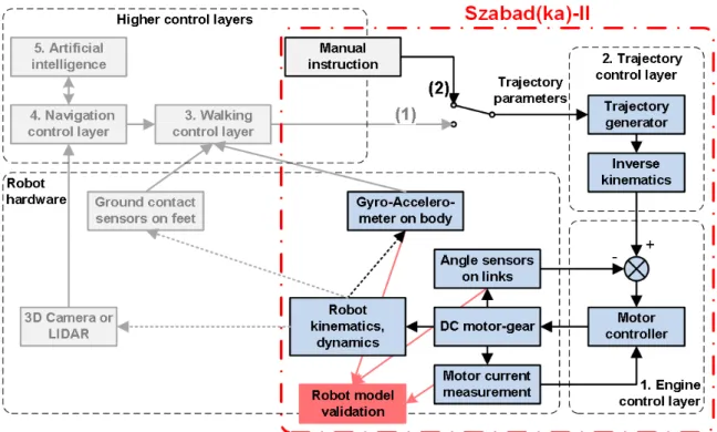
Figure 2.1: Control layers of Szabad(ka) robot series, layers of Szabad(ka)-II are highlighted.
also the models of the DC motors and the control electronics. Just like in the case of the real robot, the control part consists of a trajectory generator (with inverse kinematics) and a simple PID controller. Szabad(ka)-II includes these two lower control layers due to its mission, but the higher level layers can be included in the next generation. Fig 2.1 shows the lower and higher control layers organized in hierarchy used to establish an autonomous robot system:
1. Motor control layer – consists of 18 PID motor controllers, using the signals of the encoder and current sensors. My earlier articles Kecsk´es and Odry (2009b,a, 2010); Pap et al.
(2010) dealt with motor control, therefore this subject has not been described here in detail.
2. Trajectory control layer – generates leg trajectory for each leg based on trajectory param- eters.
3. Walking control layer – defines trajectory parameters according to the gait.
4. Navigation control layer – consist of SLAM (Simultaneous Localization and Mapping) and path-planning.
5. Artificial intelligence – top decision unit.
Therefore the model validation includes the two lowest control layers, thus the real properties of mechanical parts come to the focus. In Fig 2.1 this limitation is illustrated as a switch turned to position 2, and the trajectory parameters are determined with manual instructions. In practice these manual instructions are sent from a PC which communicates with the robot via wireless interface.
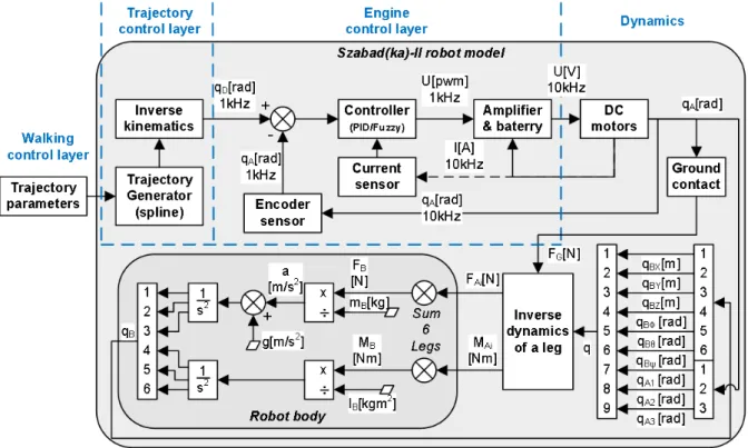
Fig. 2.2 details the simulation model of Szabak(da)-II control layers from Fig. 2.1. Besides the
structural elements it includes the names of variables, and the sample rates (F s) used in the model. The model consists of the following elements:
1. Trajectory generator – calculates the trajectory curves based on trajectory parameters.
The algorithm is the same as the one that runs in the digital control unit of the robot.
The inputs are seven trajectory parameters (Table 1 in appendix); the outputs are the three-dimensional curves of a one-step walk cycle. More details can be found in Section 2.2.1.
2. Inverse kinematics – transforms the calculated trajectory given in the world coordinate system (three-dimensional curves) into the desired angles of the links. This is also the exact copy of the algorithm running in the digital control unit of the robot. Section .2.1 in appendix provides more description.
3. Controller – a model of the PID controller running in the digital control unit of the robot.
The inputs are the angle errors; the outputs are the control signals of the PWM amplifiers.
More details are listed in Section 2.2.2.
4. Amplifier and battery – the inputs are the PWM control signals; the outputs are the control voltages that appear on the DC motors.
5. DC motors – DC motor-gearheads model of all three links of all the six legs. The inputs are the control voltages and load torques; the outputs are the angles of links and motor currents. The motor-gearhead model was validated by comparing simulation results with measured characteristics (torque graphs) given by the datasheet Faulhaber (2005). Details can be seen in Section 2.2.5.
6. Ground contact – inverse dynamical model of ground contact (connection between the feet and ground) using Carnopp friction model. Calculated the reactive forces (as output) from the ground to the leg based on the feet’s position defined by joint angles (as input). The holding force in directionZW and the friction forces inXW−YW directions. The position of the feet is given in the world coordinate system according to the ground, therefore first the forward kinematics transformation needs to be performed. The approximation model of ground contact has been discussed in Kecskes and Odry (2013). Described here in Section 2.2.6.
7. Inverse dynamics – the inverse dynamic model of the robot legs and body. The inputs are the kinematics of the body and legs (velocities ˙q and accelerations ¨q are calculated from angles/positionsq inside by derivations); the outputs are the forces acting on the leg links and the forces acting on the body by the legs. More information is provided in Sections 2.2.3.
8. Robot body – a forward dynamic model; the inputs are the sum of reactive forces and torques occurring in the six legs (equation 2.1); the output is the kinematics of the body (3D translation and 3D rotation). See Section 2.2.4.
9. Sensors – encoder and current sensors.
It is assumed that elements which do not belong to the rigid body dynamics (encoder sensor, current sensor, controller and amplifier-battery) are almost ideal or at least more accurate than the dynamic part. These elements are relatively simple and their approximation models are not critical. However, the following sections partially mention them.
Figure 2.2: Block diagram of the robot model, including trajectory and motor control layers and the main dynamic parts.
2.2.1 Walking and Trajectory Control
The hexapod walking or hexapod gait is not a universally resolved and determined subject Dinget al. (2010), however the existing solutions are comprehensive and acceptable. There are several hexapod walking types Ramanathanet al.(2010); Dinget al.(2010), such as the Tripod, Ripple and Wave gait, moreover the hexapod climbing is a topic of a separate exploration. The tripod type straight-line walking on even ground is the simplest and fastest gait. It has been assumed that in such a case the robot probably goes for a farther target point, without any maneuvers or other operations. Thus the most important task is to achieve a fast and low-cost (low energy consumption) locomotion. Therefore during the validation process I focused on this gait.
Detailed description of walking is not essential for the model validation, and is given in Appendix .2.1.
2.2.2 Motor control
In an earlier study Kecsk´es and Odry (2009c); Kecsk´eset al.(2013); Pap et al.(2010); Kecsk´es and Odry (2014) the development of the DC motor and controller model and the controller’s parameter optimization was already dealt with. This topic also included the issue of the ade- quate controller’s sampling time (sampling rate), which has already been addressed in Kecskes and Odry (2013). Further experience was gained in the development of fuzzy controllers, and
their performance was always compared with the PID controller Kecsk´es and Odry (2009b,a, 2010). The aim of further research is to reach and implement a fuzzy controller which has more advantages in more aspects:
• Reach better performance compared to other fuzzy or PID controllers in terms of energy consumption and device protection, as it introduced in Kecsk´es and Odry (2009a).
• Have sufficiently robust behavior for various loads.
• Safe behavior in case of motor and link overload as much as possible, for example, in case when the robot gets stuck, collides, falls, etc.
During this model validation and measurements only a simple P controller (P = 0.25) was implemented in the real robot.
2.2.3 Inverse Dynamics
The six legs of the Szabad(ka)-II robot have identical structure, but since they are driven by different types of motors and gearheads (see details in Table 1.1), the models of the legs differ in their parameters. Dynamic model of one leg includes three DC motors for the three joints, one ground contact, and one inverse dynamical system.
The robotics toolbox of Peter I. Corke Corke (2001) is a Matlab toolbox developed for mod- eling robot manipulators on fixed stand. It was chosen as the basis of the dynamics in my model, thus the programming of dynamic formulae was not necessary, and the Simulink implementa- tion of the robot model was faster. However, in case of walker robots the “manipulator” – i.e.
the robot leg in my case – should be attached to a moving body, and therefore this toolbox had to be modified. In 2009 when this modeling was started Kecsk´es and Odry (2009a) the higher level Simulink’s SimMechanics toolbox was not developed yet, but from 2012 my colleague also started modeling in SimMechanics Burkuset al.(2013) due to the better usability of its toolbox.
Robot body has six degrees of freedom, three translations (X, Y, Z) and three rotations (roll, pitch, yaw), while the leg has three more rotational joints. It is possible to build a nine-link robot manipulator so that the first six elements are the body’s six degrees of freedom without the weight and volume, and the last three are the actual motor-driven legs Kecsk´es and Odry (2009a). Dynamics of robot body is calculated once separately from legs’ inverse dynamics instead of attaching the same model six times to each leg. Practically the first six DOFs of nine-link legs represent only the body kinematics, and move the stand points of the last three DOFs according to the motion of the robot body. If the leg of one such manipulator is kept on the ground with force FGi3×1, and the inverse dynamics is calculated, then the forces of the leg acting on the body FAi3×1,MAi3×1 can be obtained. The same is calculated for the other five legs (”i” index in equation 2.1 refers to the leg numbering; the number in superscript designate the vector dimensions) and summarizing all these final forces are attained, which move the body in the six degrees of freedomFB3×1,MB3×1. Knowing the body weight and inertia the robot’s body kinematics is calculated using double integrationq3×1B (it is shown in Fig. 2.2).
FB3×1 = X
i=1..6
FAi3×1, MB3×1= X
i=1..6
MAi3×1 (2.1)
Furthermore, by using inverse dynamics the torques of the three leg-joints can be attained, which are feedbacked to the motor-gearheadsMLi3×1. All motors are driven by a voltage controllerUi3×1 to make the joints qA3×1 move according to the required values defined by the walking controls qD3×6. Srobot parameter structure of the robot manipulator consists of a series of Links(object defined by robotics toolbox), in the current casej ∈ {1, . . . ,9}.
In Appendix .2.2 Table 2 lists the main elements of the Link structure, and Table 3 shows the parameters of the right front leg (Leg1) required by the robot object in robotics toolbox Corke (2001). From these parameters one matrix is created and from this matrix oneserial-link object of the robot manipulator can be simply constructed. This object will be the argument for all other functions used in this toolbox which are called from Simulink at forward kinematic and inverse dynamics.
The inverse dynamics algorithm (see inverse dynamics block in Fig. 2.2) results reactive forces FA3×1 and torques MA3×1 from each leg as well as torques occurring in joints ML3×1 of each leg. This algorithm uses Recursive Newton-Euler (RNE) function of the Robot Toolbox Corke (2001), as described with equation 2.2. Table 7 in Appendix .2.2 contains variables and parameters of the inverse dynamics model.
τ = fRN E(q,q,˙ q, F¨ Gi, Srobot)∼=I(q)¨q+C(q,q) ˙˙ q+F( ˙q) +G(q) (2.2) q = [qBX, qBY, qBZ, qBφ, qBθ, qBψ, qA1, qA2, qA3] = [q6×1B , qA3×1]
τ = [FAX, FAY, FAZ, MAφ, MAθ, MAψ, ML1, ML2, ML3] = [FA3×1, MA3×1, ML3×1] 2.2.4 Robot body
Modeling of the robot body is relatively simple compared to modeling of other parts; it is based on forward dynamics, see equation 2.3 and block diagram on Fig. 2.2. Inputs are forces and torques acting on the body FB3×1, MB3×1 (the overall effect of the legs); outputs are the three- dimensional translation and the three-dimensional rotation of the body in the world coordinate system qB6×1. These movements can be deducted from Newton’s law a=F/m and the double integration of accelerations which gives the translation and rotation.
qBk[m] = Z Z
(aB+gk)dtdt= Z Z
FBk(t) mB +gk
dtdt (2.3)
qBk[rad] = Z Z
αBdtdt= Z Z
MBk(t) IBk
dtdt k∈ {X, Y, Z} (k∈ {Φ,Θ,Ψ}in case of qBk[rad]) Table 5 in Appendix .2.2 contains the parameters of the robot body.
2.2.5 DC Motor and Gearhead
Fig. 2.3 shows the block diagram of the DC motor and gearhead model, and is described by equations 2.4–2.10. The general model of the DC motor is defined with equation 2.10 and is described in detail in Krishnan (2001). The gearhead model was added to the DC motor model
Figure 2.3: Model of DC motor and gearhead
thus the complete simulation model of the motor-gearhead pair was obtained. The controller with UM voltage in the motor drive layer presented in Fig. 2.1 is directly connected to this model.
The kinematic model of the gearhead is a simple multiplication with the constant of the gear ratio rG (see equations 2.5 and 2.6). The dynamic modeling of this gearhead, however, is not so trivial due to the internal losses. These losses are modeled by transforming the gearhead’s inertia JG and the gearhead’s viscous friction BG into the motor side (see equation 2.7). By doing so these quantities can be added to the internal losses of the motor, which will be the arguments of the mechanical part of the model.
The original datasheet does not define the BM, BG and JG parameters (onlyJM is given), therefore they had to be derived. The viscous friction of the motor was obtained from the no-load operating point (equation 2.8). The viscous friction of the gearhead was approximated from the nominal speedωN G, nominal torqueMN G and efficiency ηN G given in the datasheet (equation 2.9). No solution has been found for the calculation of the gearhead’s inertia based on the parameters given in the datasheet; moreover it is impossible to measure in my laboratory.
Therefore it had to be assumed that the gearhead’s inertia equals the motor’s inertiaJG≈JM. This way the predicted value was not significantly exceeded, because the size and weight of the rotor and gear are in the same order of magnitude.
[IM, qA] = fM+G(UM, ML) (2.4)
M = ML
rG (2.5)
qA = 1 rG
Z
ω(t)dt (2.6)
J = JM +JG
r2G, B=BM +BG
r2G (2.7)
BM = KMI0 ω0
(2.8) BG = MBG
ωN G
≈ (1−ηN G)MN G ωN G
(2.9)
ω(s) = KMUM(s)
s2(J L) +s(BL+J R) + (BR+KM2 ) (2.10)
+ −(sL+R)M(s)
s2(J L) +s(BL+J R) + (BR+KM2 ) IM(s) = UM(s)−KMω(s)
sL+R
Table 4 in Appendix .2.2 summarizes the variables and parameters of the motor-gearhead model.
The gearhead simulation model had been theoretically validated by comparing the charac- teristic curves of my model with the curves given in the original Faulhaber datasheet Faulhaber (2005). Fig. 2.4 shows the characteristic curves based on my simulation, which is corresponding to the plot in datasheet. In the simulation the speed was kept constant at 5000rpmlike in the datasheet; a Faulhaber 2232012SR motor and a PID controller was used (information about the gearhead and controller is not mentioned in Faulhaber (2005)).
Figure 2.4: Model characteristics of gearhead
2.2.6 Ground contact
Figure 2.5: Schematic Model of Ground Contact
The ground contact is a special and critical topic in the modeling process, because the collision between rigid bodies is a complex problem. In order to model the realistic (non-rigid) collision between the 3D-shaped feet and the ground, one should be deeply involved in the materials science and non-rigid body dynamics. Generally this is not the subject and aim of dynamic and kinematic modeling in the field of robotics, because there is not an easy solution
(i.e. readily applicable formula) to the problem. Instead, approximate solutions, also known as soft-contact solutions, are applied. In this project one of these solutions has been chosen, which works on the spring-damper (absorber) principle Kecskes and Odry (2013). Similar absorber- based models can be found in literature Woering (2011); Haavisto and Hy¨otyniemi (2004);
Hutter and N¨af (2011); Grizzleet al.(2010); Duindam (2006), there is no other widely accepted soft-contact solution. This approximate model of ground contact (equation 2.11, Fig. 2.5) is based on the following assumptions:
• Every leg has similar parameters.
• The contact between the leg and the ground is point-contact.
• The ground has homogeneous friction.
• The ground is generally flat.
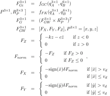
FGi3×1 = fGC(qA3×1, q6×1B ) (2.11) P3×1, R3×3P
= fF K(q3×1A , qB6×1) (2.12)
FG3×1 = (FGW3×1×R3×3P )T
FGW3×1 = [FX, FY, FZ], P3×1= [x, y, z]
FZ =
( −kz−cz˙ ifz <0
0 ifz >0 (2.13)
Fnorm =
( −FZ ifFZ >0
0 ifFZ ≤0 , (2.14)
FX =
( −sign( ˙x)δFnorm if|x|˙ > vd
0 if|x| ≤˙ vd
FY =
( −sign( ˙y)δFnorm if|y|˙ > vd
0 if|y| ≤˙ vd
The leg’s endpoint world coordinates P3×1 are calculated from the leg’s joint angles qA3×1 using forward kinematics, which is necessary to model the contact and the friction (equation 2.12). Along the Z direction one spring-damper system approximates the collision between the ground and the feet (equation 2.13). In XW and YW horizontal directions the homogeneous friction was modeled based on the Karnopp friction model Kikuuwe et al. (2005) (equation 2.14).
Table 6 in Appendix .2.2 contains the variables and parameters of the ground contact model.
2.3 Model Validation
2.3.1 Aim of Validation
The Szabad(ka)-II model was validated based on the measurements performed on the real robot.
The aim was to develop a model with adequate parameters that can be used for prospective
research (developing and optimizing the walking algorithm like in Kecsk´eset al.(2013) and Pap et al. (2010)). After implementing such a walking algorithm on the real robot it would show the same behavior, at least within an acceptable confidence interval.
As the outcome of the validation process it is expected that the difference between the results of the current model and the measurements are within a tolerances. Therefore these tolerances must be defined primarily from the aspects of walking and control.
2.3.2 Validation progress
Fig. 2.6 shows the validation procedure, where the gray blocks are measurement processes performed on the robot, the light gray blocks illustrate the simulation processes, and the white blocks show the validation processes. Basically during validation the measurements on the robot
Figure 2.6: Flow diagram of model validation progress
and the simulation results were compared. First the recorded signals were synchronized, and then statistical methods were used to quantify the differences. If the difference between these results was more than the specified tolerances, further studies were conducted to find the reason of the significant deviation. The reasons of the differences are likely to be the imperfections of the model because it is only an approximated model. Other reasons might be errors occurred in the analog or digital measurement processes. The scope of this validation also includes exploring and correcting these errors, illustrated by the feedback branches in Fig. 2.6. Before comparing the signals, two prior tasks have to be completed:
• Implementing the measurement modules and communication units on the real robot to provide the dynamic measurements taken on the robot towards the PC while walking.