"This accepted author manuscript is copyrighted and published by Elsevier. It is posted here by agreement between Elsevier and MTA. The definitive version of the text was subsequently published in [Carbon, 2019, 147, 476-482; DOI 10.1016/10.1016/j.carbon.2019.02.076]. Available under license CC-BY-NC-ND."
Photocatalytic Properties of TiO
2@Polymer and TiO
2@Carbon Aerogel Composites Prepared by Atomic Layer Deposition
Nóra Justh1, Gergő János Mikula1, László Péter Bakos1, Balázs Nagy2, Krisztina László2, Bence Parditka3, Zoltán Erdélyi3, Viktor Takáts4, János Mizsei5, Imre Miklós Szilágyi1
1Department of Inorganic and Analytical Chemistry, Budapest University of Technology and Economics, H-1111 Budapest, Szt. Gellért tér 4. Hungary;
2Department of Physical Chemistry and Materials Science, Budapest University of Technology and Economics, P.O. Box 92, H–1521 Budapest, Hungary;
3Department of Solid State Physics, University of Debrecen, H-4026 Debrecen, Hungary;
4Institute for Nuclear Research, Hungarian Academy of Sciences (Atomki), Debrecen, Hungary;
5Department of Electron Devices, Budapest University of Technology and Economics, H-1521 Budapest, Hungary
Email: imre.szilagyi@mail.bme.hu
Abstract
Monolithic structured TiO2/aerogel composites were prepared from resorcinol-formaldehyde polymer aerogel (RFA) and its carbon aerogel (RFCA) derivative. A resorcinol-formaldehyde hydrogel was synthesized in a sol-gel reaction and transformed into polymer aerogel by supercritical drying. The RFA was converted to carbon aerogel by pyrolysis at 900 °C in dry N2. Amorphous and crystalline TiO2 layers were grown from TiCl4 and H2O precursors by atomic layer deposition (ALD) at 80 °C and 250 °C, respectively, on both RFA and RFCA. The substrates and the composites were studied by N2 adsorption, TG/DTA-MS, Raman, SEM-EDX and TEM techniques. Their photocatalytic activity was compared in the UV catalyzed decomposition reaction of methyl orange dye.
Keywords
resorcinol-formaldehyde polymer aerogel, carbon aerogel, photocatalysis, ALD, TiO2
1. Introduction
Beside crystalline carbonaceous nanomaterials such as fullerene, graphene, graphene oxide, nanodiamond, carbon nanospheres, carbon nanotubes; mesoporous carbon aerogels have attracted a great deal of attention. Carbon aerogels, available also in monolithic form, have several favorable properties, for example they can be used as adsorbents or as substrates for catalysts, because of their robustness and high specific surface area [1,2]. They are also excellent thermal and phonic insulators, while conduct electricity. These properties can be tuned through their synthesis conditions. [3–7]
Resorcinol-formaldehyde (RF) organic aerogels, that Pekala and co-workers synthetized for the first time [8], undergo two main stages during preparation. In the first stage a hydrogel is prepared by a sol-gel process and in the second stage after drying the aerogel is obtained. The resorcinol-formaldehyde polymer aerogel becomes a carbon aerogel in a consecutive third stage, which is carbonization occasionally followed by activation. Depending on the conditions carbonization or activation influence the structural and performance characteristics, like the specific surface area, significantly [9–12].
Photocatalytic carbon nanocomposites have great potential in the field of environmental remediation, water splitting and self-cleaning surfaces [13,14]. Among the various semiconductor oxide photocatalysts TiO2 is researched widely, due to being stable and nontoxic. TiO2 has ideal band gap width for the half reactions of water splitting and its composites with other nanomaterials, such as carbon nanostructures, may enhance the photocatalytic activity. However, its use still faces some difficulties, such as a narrow light response range limited to UV. The carbon nanostructure inhibits the recombination by promoting the charge separation as an electron acceptor. This effect and the widening of the wavelength response range through Ti-O-C bonds as well as modifying the photocatalytic selectivity are three advantages of TiO2 composites [3,15–18]. Moreover, a number of studies indicates that nanoporous or nanostructured carbon materials, such as activated carbon or graphene-oxide, show significant photocatalytic activity by themselves, even when compared to titania. The origin of this phenomenon is said to be that they behave as semiconductors.
Their electric properties depend on their oxidized/reduced states and the number and nature
of their functional groups. Nevertheless, the photocatalytic activity of carbon nanostructures needs considerable further studies [19–24].
There are several ways how photocatalytic oxide layers can be deposited on monolithic substrates as the aerogels (e.g. sol-gel synthesis, CVD, sputtering) [18]. However, the coating of these aerogels still faces some challenges, because of their narrow pore size and high surface area. Atomic layer deposition (ALD) is a surface controlled, gas phase deposition technique and it enables the coating of complex nanostructures in a conformal and homogeneous manner, with a precise control of the grown film thickness at nanometer scale [25–30]. Therefore it is an ideal tool to coat uniformly polymer and carbon aerogels. By now, there have been several ALD depositions of semiconductor oxides on carbon substrates [3,31], however; there have been only a few metal and semiconductor oxide depositions on aerogels [32–35], and these composites were not used as photocatalysts, to the best of our knowledge.
Hence, our aim was to prepare polymer and carbon aerogel/TiO2 composites from resorcinol- formaldehyde aerogel (RFA) and its carbon aerogel (RFCA) derivative by ALD. The RF hydrogel was prepared by sol-gel method from resorcinol and formaldehyde. In the second stage the wet gel was dried in supercritical CO2 to obtain the polymer aerogel (RFA). The carbon aerogel (RFCA) was obtained by pyrolyzation at 900 °C. TiO2 was grown from TiCl4 and H2O precursors at 80 °C and 250 °C on both RFA and RFCA aerogels by ALD. Deposited at 80 °C, the TiO2 was amorphous, while at 250 °C it was crystalline. The substrates and the composites were examined by several techniques: N2 adsorption, TG/DTA-MS, Raman, SEM-EDX and TEM. To test the application of the composites their photocatalytic properties were studied. The decomposition of methyl-orange dye under UV radiation was followed by UV-Vis technique.
2. Materials and Methods
2.1. Preparation of resorcinol-formaldehyde polymer aerogel (RFA)
RF polymer hydrogel was prepared by the method of Pekala modified by Lin and Ritter. The aqueous precursor solution contained resorcinol (R) (Merck), formaldehyde (F) (37 % aq.
solution, Merck) and sodium carbonate (C) (Reanal) as catalyst [8,9]. The R/F and R/C molar ratios were 0.5 and 50, respectively, and the overall concentration of the solution was 5 w/w%. The initial pH was adjusted to 6.0 with diluted HNO3. After 30 min stirring the sol was sealed into glass vials (i.d. 4 mm, length ca. 10 cm) and cured at 85 °C for 7 days. Over the one-
week period the initially colorless solution became brick red as the RF hydrogel was forming.
After the seven-day incubation the water content of the hydrogel rods was exchanged to acetone, which was removed by supercritical CO2 to yield the polymer aerogel.
2.2. Preparation of the carbon aerogel (RFCA)
Polymer aerogels were converted to carbon in a rotary quartz reactor for 1 h under high purity dry nitrogen flow (99.996 %, Linde, 25 mL/min) at 900 °C.
2.3. Atomic layer deposition on the substrates
TiO2 was deposited on the aerogel substrates in a Beneq TFS-200-186 flow type thermal ALD reactor using TiCl4 and H2O as precursors. The pulse times were 0.3 s for both the metal and oxygen precursors, 3 s for the nitrogen purge between them, and 200 ALD cycles were used.
The depositions were carried out at 80 °C and 250 °C, the pressure in the reactor was 1 mbar.
2.4. Characterization
TG/DTA-MS measurements were conducted on a TA Instruments SDT 2960 simultaneous TG/DTA device in He atmosphere (130 mL /min) using an open platinum crucible and 10 °C/min heating rate. EGA-MS (evolved gas analytical) curves were recorded by a Balzers Instruments Thermostar GSD 200T quadruple mass spectrometer (MS) coupled on-line to the TG/DTA instrument. The on-line coupling between the two parts was provided through a heated (T=200 °C), 100 % methyl deactivated fused silica capillary tube (inner diameter of 0.15 mm).
SEM-EDX data were obtained by a JEOL JSM-5500LV scanning electron microscope after sputtering an Au/Pd layer on the samples. The average EDX data (neglecting the sputtered layer) were calculated from 6 measured points at each sample.
Powder XRD patterns were recorded on a PANanalytical X’Pert Pro MPD X-ray diffractometer using Cu Kα radiation.
TEM images were taken with a FEI Morgagni 268 transmission electron microscope operating at 300 keV. Prior to the measurements. The samples were dispersed in EtOH, dropped on Cu grids and covered with a 10 nm Formvar film.
Raman spectra were collected with an Olympus BX41 microscope combined with a Jobin Yvon Labram microspectroscope using a frequency duplicated green Nd-YAG laser with a wavelength of 532 nm. The spectra were taken in the 100 to 1800 cm-1 range.
Nitrogen adsorption was measured at -196 °C with a NOVA 2000e (Quantachrome) computer controlled volumetric gas adsorption apparatus. Pre-treatment of the samples was performed at 100 °C at 3 x10⁻⁴ mbar pressure for 24 h. The apparent surface area (SBET) was calculated from the Brunauer–Emmett–Teller (BET) model. The NLDFT equilibrium model with slit/pore geometry gave the best fit for the pore size distribution of the carbon aerogel. As no kernel is available for polymers and TiO2 doped substrates, the same model was used to estimate the pore size distribution of all the composites.
Diffuse reflectance spectra were collected was between 250 and 800 nm on a JASCO V-750 UV-VIS spectrophotometer equipped with an integrating sphere. The reference material was BaSO4.
Photoluminescence spectra were recorded on a Edinburgh Instruments FS5 spectrofluorometer, using four different excitation wavelengths: 320, 380, 480 and 600 nm.
For photocurrent tests, the samples were placed on interdigitated platinum electrodes on Al2O3 substrates. The resistance was measured by a Keithley 616 Digital Electrometer with and without UV light irradiation. The light source was the same as the UV light used for the photocatalytic experiments, and it was 2 cm away from the samples.
X-ray photoelectron spectra (XPS) were taken on a PHOIBOS HSA3500 100 R6 machine. The specimens were put on silicon sample holders. The data were evaluated by CasaXPS software using Shirly background.
2.5. Photocatalysis
The photocatalytic activity of the RFA and RFCA composites was determined from their methyl orange (MO) degradation capability under UV light at 25 °C. In a 4 mL quartz cuvette 1.0 mg sample was suspended in 3 ml 4×10⁻⁵ mol/L MO solution. The RFA related samples were kept in dark for 90 minutes to reach constant absorbance. In order to obtain reliable photocatalysis data on the RFCA related gels, the initial MO concentration was doubled (8x10⁻⁵ mol/L) and the suspensions were kept in dark for 24 h. After the dark adsorption the cuvettes were placed between two parallel UV lamps (Osram 18 W UV-A blacklights), 5 cm away from each lamp.
The decomposition of MO was followed by measuring the absorption at 464 nm in every
30 min by a Jasco V-550 UV-Vis spectrophotometer. The relative absorbance (the absorbance after an irradiation time t, related to the absorbance at t=0) was calculated so that the results could be compared. For reference material, Degussa P25 TiO2 was used.
3. Results and discussion
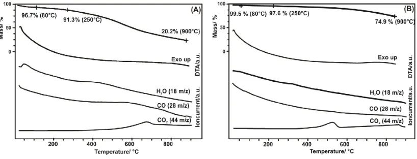
The thermoanalytical curves of the RFA and RFCA substrates are presented in Figure 1. When heating the RFA in inert He atmosphere to 900 °C, it goes through a significant mass loss, i.e.
79.8 % (Figure 1. A), which is due to the release of the retained solvent and at higher temperature to the degradation of the polymer allowing the detection of water, carbon monoxide and dioxide. Basically, a similar process takes place when the RFA is converted to RFCA in inert N2 atmosphere. At the relatively low temperature (80 and 250 °C), where the ALD was performed, the mass loss of the RFA is only a few percent, i.e. the polymer gel is hardly damaged. Hence, at the chosen ALD reaction temperatures there are sufficient remaining polar nucleation sites for the deposition [36,37]. Upon annealing the RFCA has a considerably lower mass loss, only 25.1 % at 900 °C (Figure 1. B). Although this substrate is the pyrolyzation product of RFA, some of the degradation products might be entrapped in the matrix. Moreover, when the as-prepared RFCA comes in contact with ambient air after cooling down in nitrogen, it could react with the atmospheric oxygen. Accordingly, H2O, CO and CO2
can be still detected due to the decomposition of the functional groups of RFCA.
SEM images were taken about the substrates and the composites (Figure S1). Based on EDX data (Table 1 and Table S1), the estimated O content is considerably lower and the C content is much higher in the RFCA than in the RFA, showing the effect of pyrolysis. These pictures reveal the porous 3D structure of the RFA and RFCA aerogels formed by interconnected spherical building units. The ALD TiO2 films deposited at both 80 and 250 °C uniformly coat elementary spherical beads of both RFA and RFCA. According to EDX data, Ti was detected in all the deposited samples, i.e. the TiO2 growth was successful on both substrates at both temperatures. Moreover, the O content increased in the composites, a sign of the as- deposited oxide material. Traces of Cl were also detected in the composite samples; as residual impurity from the TiCl4 precursor.
The apparent surface area of the samples was determined by N2 adsorption using the BET- model (Table 2). The estimated effect of the carbonization and ALD on the pore size
distribution is shown in Figure S2. Due to the pyrolyzation process the surface area of the carbon aerogel became three times higher, compared to the polymer aerogel. In the case of the RFA the deposition of the ALD oxide did not change SBET remarkably; the surface area of the composites only differs a few 10 m2/g smaller than for the bare RFA. In contrast, the TiO2
deposition on the RFCA substrate lowered its surface area to its 3/4. The reason for this is that the density of RFA is ca. 0.1 g/cm3 and that even lowers during the carbonization process [8].
Crystalline anatase TiO2 has a density of 3.9 g/cm3 [32]. When a high density oxide is deposited on a light weight material, and there is no significant change in the morphology, the average density increases, leading to a decrease in the specific surface area [39–41].
The TEM images taken of the composites deposited at 250 °C are presented in Figure 2. The RFA and RFCA substrates have similar porous structure, featuring the 3D network of beads. In Figure 2a we can see the as-grown oxide layers on the RFA substrate, showing the excellent quality of ALD deposited layers. On Figure 2b the RFCA/TiO2 composites are shown. Here, in some cases island type growth mechanism is visible. The thickness of the layers was approximately 7 nm in the case of RFA/TiO2/250, and around 5 nm for the RFCA/TiO2/250.
Figure 3 shows the Raman spectra of the samples. The characteristic D (diamond/defect, sp3, 1582 cm-1) and G (graphite, sp2, 1332 cm-1) carbon peaks appear on all spectra. The RFA polymer certainly contains abundant amount of heteroatoms, it is less structured and the D and G peaks are wider (Figure 3a). As the result of the pyrolysis the RFCA has more defined D and G peaks (Figure 3b) [39–41]. In the composites, the crystalline TiO2 has characteristic Raman peaks, among them the 141 cm-1 is the most significant [42]. Both composites deposited at 250 °C contain this distinguishable, intensive 141 cm-1 peak, but the ones grown at 80 °C do not. This means that the oxide layers grown at 250 °C are crystalline (anatase), while the ones deposited at 80 °C are amorphous [42]. Examples of amorphous TiO2 deposited by low temperature ALD can be found in the literature [28,43–45].
Based on the powder XRD data both the polymer and carbon aerogels are amorphous (Figure S3). At this scale the aerogels are not arranged in a highly ordered structure; therefore, the amorphous nature of the substrates is expected. Deposited at 80 °C, the TiO2 is amorphous, while at 250 °C it is crystalline (anatase). Unfortunately, no TiO2 peaks could be detected probably due to the low amount of TiO2 deposited.
Diffuse reflectance spectra in Figure S4 shows that the RFA absorbs light uniformly below 500 nm, while above that the absorbance decreases, as it is an orange colored material. After
TiO2 deposition, the color and the spectrum remain similar, but the absorption edge of the TiO2 appears around 390 nm. The RFCA is black, even after the atomic layer deposition of TiO2; thus, the RFCA and its TiO2 composite absorb light across the entire measured wavelength range. The absorption edge of the titania is not visible in this case.
Photoluminescence spectra (Fig. S5-8) depict no activity for the RFA and RFCA. Although TiO2
by itself is usually active in photoluminescence, no activity was observed from samples RFA/TiO2/250°C and RFCA/TiO2/250°C. No TiO2 related peaks are visible, because it is present only as a very thin layer on the aerogel substrates. There were no photoluminescent peaks related to the interaction between the aerogels and the TiO2 as well.
In the photocurrent measurements, anatase TiO2 (Sigma-Aldrich) was tested for reference, and it revealed a clear photoelectric effect. Its resistance decreased from 31.4 GΩ to 22.1 GΩ under UV light (30 % change), because of the generated charge carriers. RFA had no photoelectric response; its resistance was 25.4 GΩ and stayed the same under UV irradiation.
After TiO2 deposition, the RFA/TiO2/250°C showed obvious photocurrent, as its initial 20.1 GΩ resistance decreased to 15.5 GΩ under UV light, which corresponded to a 23 % reduction. The carbonized aerogel, the RFCA was a significantly better conductor with its 20 kΩ resistance, compared to RFA, however, it was not affected by the UV light. The composite RFCA/TiO2/250°C had base 0.65 MΩ resistance. In the case of this sample, no photoelectric effect was observable under UV irradiation. This composite had much lower initial resistance than the as-deposited anatase TiO2. Although the photogenerated charge carriers improved the conductivity of the TiO2 layer, this was such a small effect compared to the much more conductive RFCA substrate, that it was below the detection limit.
XPS spectra could only be taken from the RFA and RFCA (Fig S9-10), while from the Ti containing composites not. Table 3 shows the relative amount of the different carbon bonds on samples RFA and RFCA. The amount of C-C bonds increased after the carbonization process, as the amount of C-O-C and O-C=O decreased, but they are still present on the RFCA. The measured Si signal is explained with the silicon sample holder.
The photocatalytic activity is affected by various experimental conditions, i.e., the surface area, the number of active sites, the concentration of the dye molecules present, the occupation of the active centers, the orientation of the adsorbed dye, the kinetics of the adsorption, decomposition and the desorption of the degradation products, the diffusion and local pH conditions, etc. Moreover, the mechanism of the catalysis might be different on the
chemically significantly different surfaces. Even in the case of chemically similar species various crystalline forms show drastically different activity. Although the SEM images show a continuous layer deposition, it cannot be excluded that the MO molecules have access directly to the substrate surface as well.
In our experiments prior to the catalytic test the adsorption equilibrium of the dye molecules was practically achieved, nevertheless, with the different samples it resulted in different surface coverage. The whole UV-Vis spectrum was recorded each time to follow the concentration of the remaining MO. The position of the maximum was always at 464 nm.
The results of the photocatalytic test are demonstrated in Figure 4. Figure 4a shows that the RFA alone degrades the MO dye slightly under UV light [46]. This photocatalytic effect becomes more significant after growing TiO2 on the RFA substrate [39,40,47]. Due to the relatively similar surface area the results can be directly compared. Even the 80 °C ALD TiO2
containing composite has a stronger photocatalytic activity with the amorphous oxide layer.
The RFA composite with the crystalline anatase TiO2 proved to be the most effective among them, as anatase is known to have high photocatalytic activity.
In the case of the RFCA composites more effective photocatalytic activity was achieved than in the case of the RFA, due to the higher surface area and more active reaction sites of the substrate (Figure 4b). Unexpectedly, the bare RFCA substrate was proved to be more active photocatalyst than its composites. According to the N2 adsorption data (Table 2) the TiO2
deposition reduces the apparent surface are of the RFCA substrate. Since for the photocatalytic measurements samples with identical mass were used, the surface area and perhaps the number of active sites were lower in the samples after the ALD oxide growth. To compensate this, the relative absorbance was normalized to the surface area to get comparable results. The 80 °C RFCA composite was used as the base of the normalization, e.g.
𝐴’ 𝑅𝐹𝐶𝐴 𝑇𝑖𝑂2 (250 °𝐶) =𝐴 𝑅𝐹𝐶𝐴 TiO2 (250°C) *S 𝑅𝐹𝐶𝐴 𝑇𝑖𝑂2 (250 °𝐶) /S 𝑅𝐹𝐶𝐴𝑇𝑖𝑂2 (80 °𝐶). The normalized photocatalytic data for RFCA and their composites can be found in Figure 4c. Now, based on the compensated curves the 80 °C composite with the amorphous TiO2 is a better photocatalyst than the RFCA substrate. However, the 250 °C ALD TiO2 coated RFCA composite still has lowest photocatalytic activity, compared to the bare RFCA. As was demonstrated on the TG/DTA-MS curves (Figure 1b) the RFCA loses functional groups, when heated to 250 °C, and this may have a deteriorating effect on photocatalysis. In the case of RFA, when heated to 250 °C, still considerable amount of heteroatoms are there in the structure (Figure 1a). To
test this, the bare RFCA was heated to 250 °C in N2 atmosphere to simulate the effect of heat treatment on the substrate during the ALD process. We presumed that this heat treatment does not change the BET surface area. This heated substrate was also tested for photocatalytic activity and normalized with the specific surface area of the RFCA substrate. After the 250 °C inert atmosphere annealing, the photocatalytic activity of the RFCA decreased. Now, compared to annealed RFCA, the composite with the 250 °C ALD deposited anatase TiO2
shows a better performance, demonstrating that the deposited oxide layers increased the photocatalytic activity of the RFCA substrate. Interestingly, the RFCA/80 °C amorphous TiO2
composite is more active photocatalyst, than the RFCA/250 °C crystalline TiO2 composite. This might be explained by i) the sample contains less TiO2 and in spite of the visibly continuous coverage, the MO molecules have also access to the reactive photocatalytic sites of RFCA; ii) the TiO2 is much better distributed and provide more advantageous access to the catalytic decomposition. Nevertheless, the fact that amorphous TiO2 grown by ALD has photocatalytic effect is an unexpected result. TiO2 was considered to be an active photocatalyst only in crystalline form. Recently, amorphous TiO2 grown by low temperature ALD on lotus leaf [28]
or on C60-OH [45] also showed also photocatalytic property. Our present result is a further support for this phenomenon.
4. Conclusions
In this study the application of the atomic layer deposition was extended for depositing TiO2
on resorcinol-formaldehyde aerogel (RFA) and carbon aerogel (RFCA) substrates to obtain composites for photocatalytic purposes. The samples were studied by N2 adsorption, TG/DTA- MS, Raman, SEM-EDX and TEM. The aerogels were made up by a 3D chain of spherical beads.
Due to the low ALD temperature at 80 °C, the TiO2 deposited on both substrates was amorphous, while grown at 250 °C it was in crystalline anatase phase. The RFA had negligible photocatalytic activity, while the crystalline TiO2 deposited on it increased it significantly, and even the amorphous TiO2 had observable photocatalytic property. Our results clearly demonstrate that the RFCA substrate alone has photocatalytic activity, owing to its higher specific surface area and semiconductor nature. When RFCA was covered with amorphous or crystalline TiO2 by ALD, unexpectedly the photocatalytic activity decreased. This was rationalized by that due the oxide coating the average density and hence the specific surface
area of the RSCA decreased, yielding a lower photocatalytic performance. In addition, the heat treatment of the RFACE substrate during the ALD reaction at 250 °C resulted loss of functional groups and photocatalytic reactive sites. When the decrease in specific surface area and the annealing effect were compensated, it was obvious that the ALD TiO2 layers improved significantly the photocatalytic activity of RFCA. All carbonized samples showed better activity than the reference P25 TiO2.
As a conclusion, when porous carbon nanostructures are coated by ALD oxide layers, several factors have to be taken into account when studying the composites in various applications.
The ALD layer might improve certain properties or provide new functionalities. However, the change in overall density and hence in specific surface are must be paid attention to, and it might be considered how much the heat treatment, which the substrate receives during the ALD reaction, might change the functional properties of the substrates.
Interestingly, photocatalytic property of amorphous TiO2 grown by ALD was confirmed. It is obvious that low temperature ALD of photocatalytic amorphous TiO2 has a high potential, and can be used in e.g. coating highly structured heat sensitive substrates with self-cleaning films.
Declarations of interest: none
Acknowledgements
I. M. Szilágyi thanks for a János Bolyai Research Fellowship of the Hungarian Academy of Sciences. The ÚNKP-18-4-BME-238 New National Excellence Program of the Ministry of Human Capacities, Hungary. A GINOP-2.2.1-15-2017-00084, an NRDI K 124212 and an NRDI TNN_16 123631 grants are acknowledged. The work performed within project VEKOP-2.3.2- 16-2017-00013 was supported by the European Union and the State of Hungary, co-financed by the European Regional Development Fund. The research reported in this paper was supported by the Higher Education Excellence Program of the Ministry of Human Capacities in the frame of Nanotechnology and Materials Science research area of Budapest University of Technology (BME FIKP-NAT). The research was financed by the Higher Education Institutional Excellence Programme of the Ministry of Human Capacities in Hungary, within the framework of the Energetics thematic programme of the University of Debrecen. The authors thank Prof. Miklós Kubinyi and Dr. Zoltán Szakács (Department of Physical Chemistry
and Materials Science, Budapest University of Technology and Economics) for the photoluminescence measurements.
References
[1] H. Maleki, N. Hüsing, Current status, opportunities and challenges in catalytic and photocatalytic applications of aerogels: Environmental protection aspects, Appl. Catal.
B Environ. 221 (2018) 530–555. doi:10.1016/J.APCATB.2017.08.012.
[2] G.M. Pajonk, Some catalytic applications of aerogels for environmental purposes, Catal. Today. 52 (1999) 3–13. doi:10.1016/S0920-5861(99)00057-7.
[3] R. Leary, A. Westwood, Carbonaceous nanomaterials for the enhancement of TiO2 photocatalysis, Carbon N. Y. 49 (2011) 741–772. doi:10.1016/j.carbon.2010.10.010.
[4] Q. Xiang, J. Yu, M. Jaroniec, Graphene-based semiconductor photocatalysts., Chem.
Soc. Rev. 41 (2012) 782–96. doi:10.1039/c1cs15172j.
[5] S. Ravi, S. Vadukumpully, Sustainable carbon nanomaterials: Recent advances and its applications in energy and environmental remediation, J. Environ. Chem. Eng. 4 (2016) 835–856. doi:10.1016/j.jece.2015.11.026.
[6] C. Santhosh, V. Velmurugan, G. Jacob, S.K. Jeong, A.N. Grace, A. Bhatnagar, Role of nanomaterials in water treatment applications: A review, Chem. Eng. J. 306 (2016).
doi:http://dx.doi.org/10.1016/j.cej.2016.08.053.
[7] P.. You, S.K. Kamarudin, Recent Progress of Carbonaceous Materials In Fuel Cell Applications: An Overview, Chem. Eng. J. 309 (2016) 489–502.
doi:10.1016/j.cej.2016.10.051.
[8] R.W. Pekala, L. Liverrnore, Organic aerogels from the polycondensation of resorcinol with formaldehyde, J. Mater. Sci. 24 (1989) 3221–3227. doi:10.1007/BF01139044.
[9] C. Lin, J. a. Ritter, Effect of synthesis pH on the structure of carbon xerogels, Carbon N.
Y. 35 (1997) 1271–1278. doi:10.1016/S0008-6223(97)00069-9.
[10] O. Czakkel, K. Marthi, E. Geissler, K. László, Influence of drying on the morphology of resorcinol-formaldehyde-based carbon gels, Microporous Mesoporous Mater. 86 (2005) 124–133. doi:10.1016/j.micromeso.2005.07.021.
[11] O. Czakkel, E. Geissler, I.M. Szilágyi, K. László, TiO2-doped resorcinol–formaldehyde (RF) polymer and carbon gels with photocatalytic activity, Nanomater. Environ. 1
(2013) 23–30. doi:10.2478/nanome-2013-0001.
[12] B. Nagy, O. Czakkel, K. László, Novel synthesis route of metal doped resorcinol- formaldehyde polymer xerogels with tuned porosity, Microporous Mesoporous Mater. 185 (2014) 66–71. doi:10.1016/j.micromeso.2013.11.004.
[13] X. Shao, W. Lu, R. Zhang, F. Pan, Enhanced photocatalytic activity of TiO2-C hybrid aerogels for methylene blue degradation, Sci. Rep. 3 (2013) 3018.
doi:10.1038/srep03018.
[14] A.M. Ramirez, N. De Belie, Application of TiO2 Photocatalysis to Cementitious Materials for Self-Cleaning Purposes, in: Appl. Titan. Dioxide Photocatal. to Constr.
Mater., Springer Netherlands, Dordrecht, 2011: pp. 11–15. doi:10.1007/978-94-007- 1297-3_3.
[15] J. Schneider, M. Matsuoka, M. Takeuchi, J. Zhang, Y. Horiuchi, M. Anpo, D.W.
Bahnemann, Understanding TiO 2 Photocatalysis : Mechanisms and Materials, Chem.
Rev. 114 (2014) 9919–9986. doi:10.1021/cr5001892.
[16] G. Liu, L. Wang, H.G. Yang, H.M. Cheng, G.Q. Lu, Titania-based photocatalysts - Crystal growth, doping and heterostructuring, J. Mater. Chem. 20 (2010) 831–843.
doi:10.1039/b909930a.
[17] V. Apostolopoulou, J. Vakros, C. Kordulis, A. Lycourghiotis, Preparation and characterization of [60] fullerene nanoparticles supported on titania used as a photocatalyst, Colloids Surfaces A Physicochem. Eng. Asp. 349 (2009) 189–194.
[18] N.R. Khalid, A. Majid, M.B. Tahir, N.A. Niaz, S. Khalid, Carbonaceous-TiO2
nanomaterials for photocatalytic degradation of pollutants: A review, Ceram. Int. 43 (2017) 14552–14571. doi:10.1016/j.ceramint.2017.08.143.
[19] J. Matos, V. Fierro, R. Montaña, E. Rivero, A.M. de Yuso, W. Zhao, A. Celzard, High surface area microporous carbons as photoreactors for the catalytic
photodegradation of methylene blue under UV–vis irradiation, Appl. Catal. A Gen. 517 (2016) 1–11. doi:10.1016/j.apcata.2016.02.031.
[20] L.F. Velasco, R.J. Carmona, J. Matos, C.O. Ania, Performance of activated carbons in consecutive phenol photooxidation cycles, Carbon N. Y. 73 (2014) 206–215.
doi:10.1016/j.carbon.2014.02.056.
[21] L.F. Velasco, I.M. Fonseca, J.B. Parra, J.C. Lima, C.O. Ania, Photochemical behaviour of activated carbons under UV irradiation, Carbon N. Y. 50 (2012) 249–258.
doi:10.1016/j.carbon.2011.08.042.
[22] L.F. Velasco, J.B. Parra, C.O. Ania, Role of activated carbon features on the photocatalytic degradation of phenol, Appl. Surf. Sci. 256 (2010) 5254–5258.
doi:10.1016/j.apsusc.2009.12.113.
[23] N. Justh, B. Berke, K. László, L.P. Bakos, A. Szabó, K. Hernádi, I.M. Szilágyi, Preparation of graphene oxide/semiconductor oxide composites by using atomic layer deposition, Appl. Surf. Sci. 453 (2018) 245–251. doi:10.1016/j.apsusc.2018.05.064.
[24] S. Perathoner, C. Ampelli, S. Chen, R. Passalacqua, D. Su, G. Centi, Photoactive materials based on semiconducting nanocarbons – A challenge opening new possibilities for photocatalysis, J. Energy Chem. 26 (2017) 207–218.
doi:10.1016/j.jechem.2017.01.005.
[25] S.M. George, Atomic layer deposition: an overview., Chem. Rev. 110 (2010) 111–31.
doi:10.1021/cr900056b.
[26] I.M. Szilágyi, D. Nagy, Review on one-dimensional nanostructures prepared by electrospinning and atomic layer deposition, J. Phys. Conf. Ser. 559 (2014) 012010.
doi:10.1088/1742-6596/559/1/012010.
[27] M. Knez, K. Nielsch, L. Niinistö, Synthesis and Surface Engineering of Complex Nanostructures by Atomic Layer Deposition, Adv. Mater. 19 (2007) 3425–3438.
doi:10.1002/adma.200700079.
[28] I.M. Szilágyi, G. Teucher, E. Härkönen, E. Färm, T. Hatanpää, T. Nikitin, L. Khriachtchev, M. Räsänen, M. Ritala, M. Leskelä, Programming nanostructured soft biological
surfaces by atomic layer deposition., Nanotechnology. 24 (2013) 245701.
doi:10.1088/0957-4484/24/24/245701.
[29] H. Kim, H.-B.-R. Lee, W.-J. Maeng, Applications of atomic layer deposition to
nanofabrication and emerging nanodevices, Thin Solid Films. 517 (2009) 2563–2580.
doi:10.1016/j.tsf.2008.09.007.
[30] C. Marichy, M. Bechelany, N. Pinna, Atomic Layer Deposition of Nanostructured Materials for Energy and Environmental Applications, Adv. Mater. 24 (2012) 1017–
1032. doi:10.1002/adma.201104129.
[31] C. Marichy, N. Pinna, Carbon-nanostructures coated/decorated by atomic layer deposition: Growth and applications, Coord. Chem. Rev. 257 (2013) 3232–3253.
doi:10.1016/j.ccr.2013.08.007.
[32] J.S. King, A. Wittstock, J. Biener, S.O. Kucheyev, Y.M. Wang, T.F. Baumann, S.K. Giri, A.
V. Hamza, M. Baeumer, S.F. Bent, Ultralow loading Pt nanocatalysts prepared by atomic layer deposition on carbon aerogels, Nano Lett. 8 (2008) 2405–2409.
doi:10.1021/nl801299z.
[33] J.W. Elam, J.A. Libera, M.J. Pellin, A. V. Zinovev, J.P. Greene, J.A. Nolen, Atomic layer deposition of W on nanoporous carbon aerogels, Appl. Phys. Lett. 89 (2006) 1–4.
doi:10.1063/1.2245216.
[34] F. Yang, J. Zhu, X. Zou, X. Pang, R. Yang, S. Chen, Y. Fang, T. Shao, X. Luo, L. Zhang, Three-dimensional TiO 2 /SiO 2 composite aerogel films via atomic layer deposition with enhanced H 2 S gas sensing performance, Ceram. Int. 44 (2018) 1078–1085.
doi:10.1016/j.ceramint.2017.10.052.
[35] A.U. Mane, J.P. Greene, J.A. Nolen, U. Sampathkumaran, T.W. Owen, R. Winter, J.W.
Elam, Refractory nanoporous materials fabricated using tungsten atomic layer deposition on silica aerogels, Appl. Surf. Sci. 258 (2012) 6472–6478.
doi:10.1016/j.apsusc.2012.03.063.
[36] F. Scholz, Active sites of heterogeneous nucleation understood as chemical reaction sites, Electrochem. Commun. 13 (2011) 932–933. doi:10.1016/J.ELECOM.2011.06.003.
[37] P. Veselá, V. Slovák, Monitoring of N-doped organic xerogels pyrolysis by TG-MS, in: J.
Therm. Anal. Calorim., Springer Netherlands, 2013: pp. 209–217. doi:10.1007/s10973- 012-2923-0.
[38] M. Castellote, N. Bengtsson, Principles of TiO2 Photocatalysis, in: Appl. Titan. Dioxide Photocatal. to Constr. Mater., Springer Netherlands, Dordrecht, 2011: pp. 5–10.
doi:10.1007/978-94-007-1297-3_2.
[39] Y. Jin, M. Wu, G. Zhao, M. Li, Photocatalysis-enhanced electrosorption process for degradation of high-concentration dye wastewater on TiO2/carbon aerogel, Chem.
Eng. J. 168 (2011) 1248–1255. doi:10.1016/J.CEJ.2011.02.026.
[40] Y. Wang, Z. Pan, D. Qin, S. Bai, Q. Peng, Preparation of Ce-TiO2/carbon aerogel electrode and its performance in degradation of 4-chlorophenol, J. Rare Earths.
(2018). doi:10.1016/J.JRE.2017.10.006.
[41] S. Wang, Y. Xu, M. Yan, Z. Zhai, B. Ren, L. Zhang, Z. Liu, Comparative study of metal- doped carbon aerogel: Physical properties and electrochemical performance, J.
Electroanal. Chem. 809 (2018) 111–116. doi:10.1016/J.JELECHEM.2017.12.045.
[42] N. Wetchakun, B. Incessungvorn, K. Wetchakun, S. Phanichphant, Influence of calcination temperature on anatase to rutile phase transformation in TiO2
nanoparticles synthesized by the modified sol–gel method, Mater. Lett. 82 (2012) 195–198. doi:10.1016/J.MATLET.2012.05.092.
[43] I.S. Kim, R.T. Haasch, D.H. Cao, O.K. Farha, J.T. Hupp, M.G. Kanatzidis, A.B.F.
Martinson, Amorphous TiO 2 Compact Layers via ALD for Planar Halide Perovskite Photovoltaics, ACS Appl. Mater. Interfaces. 8 (2016) 24310–24314.
doi:10.1021/acsami.6b07658.
[44] M. Li, X. Li, W. Li, X. Meng, Y. Yu, X. Sun, Atomic layer deposition derived amorphous TiO2 thin film decorating graphene nanosheets with superior rate capability,
Electrochem. Commun. 57 (2015) 43–47. doi:10.1016/J.ELECOM.2015.05.005.
[45] N. Justh, T. Firkala, K. László, J. Lábár, I.M. Szilágyi, Photocatalytic C60-amorphous TiO2 composites prepared by atomic layer deposition, Appl. Surf. Sci. 419 (2017) 497–
502. doi:10.1016/J.APSUSC.2017.04.243.
[46] G. Zhang, C. Ni, L. Liu, G. Zhao, F. Fina, J.T.S. Irvine, Macro-mesoporous resorcinol–
formaldehyde polymer resins as amorphous metal-free visible light photocatalysts, J.
Mater. Chem. A. 3 (2015) 15413–15419. doi:10.1039/C5TA03628C.
[47] Y. Zhang, Y. Jin, X. Huang, H. Shi, G. Zhao, H. Zhao, Nanocrystalline {001} TiO2/carbon aerogel electrode with high surface area and enhanced photoelectrocatalytic
oxidation capacity, Electrochim. Acta. 130 (2014) 194–199.
doi:10.1016/J.ELECTACTA.2014.03.010.
Figures
Figure 1. TG/DTA-MS results of (A): RFA and (B): RFCA substrates.
Figure 2. TEM pictures of (A): RFA/TiO2/250°C and (B): RFCA/TiO2/250°C composites
Figure 3. Raman spectra of the RFA and RFCA substrates and their composites
Figure 4. Photocatalytic results of (A): RFA and its composite, (B): RFCA and its composites and (C): specific surface area and heating corrected data of RFCA and its composites.
Tables
Sample Element (atom %)
C O Cl Ti
RFA 77.5 22.5 0.0 0.0
RFA/TiO2/80°C 73.0 26.0 0.2 0.7
RFA/TiO2/250°C 64.3 32.6 0.3 2.9
RFCA 94.7 5.3 0.0 0.0
RFCA/TiO2/80°C 91.8 7.8 0.1 0.3
RFCA/TiO2/250°C 89.3 8.7 0.3 1.8
Table 1. EDX data of the samples
Sample SBET
m2/g
RFA 262
RFA/TiO2/80°C 242 RFA/TiO2/250°C 232
RFCA 870
RFCA/TiO2/80°C 615 RFCA/TiO2/250°C 645
Table 2. Apparent surface area (SBET) of the samples
Bond Concentration in sample (%)
RFA RCA
C-C 65.11 77.54
O-C=O 6.87 4.23
C-O-C 18.37 14.90
C-Si 9.66 3.32
Table 3. XPS results