Flame retardancy of microcellular poly(lactic acid) foams prepared by supercritical CO2-assisted extrusion
Dániel Vadas1, Tamás Igricz1, Johan Sarazin2, Serge Bourbigot2,György Marosi∗1, Katalin Bocz1
1Department of Organic Chemistry and Technology, Faculty of Chemical Technology and Biotechnology, Budapest University of Technology and Economics, Műegyetem rkp. 3., H-1111 Budapest, Hungary
2R2Fire group/UMET – UMR CNRS 8207, ENSCL, University of Lille, France
Abstract
Flame-retardant-treated cellulose (FR-cell) was used as bio-based charring agent in combination with ammonium polyphosphate (APP) based intumescent flame retardant (IFR) system to reduce the flammability of poly(lactic acid) (PLA) foams produced by supercritical carbon dioxide (sc-CO2) assisted extrusion. FR-cell was obtained by surface treatment of cellulose with diammonium phosphate (DAP) and boric acid (BA). To enhance foamability, the inherently low melt strength and slow crystallization rate of PLA was increased by adding epoxy-based chain extender (CE) and montmorillonite (MMT) nanoclay, respectively. The morphology of the foams was examined using water displacement method, scanning electron microscopy (SEM) and energy dispersive X-ray spectrometry (EDS). Thermal properties were assessed using differential scanning calorimetry (DSC) and thermogravimetric analysis (TGA). Flammability was evaluated by limiting oxygen index (LOI) UL-94 test and pyrolysis combustion flow calorimetry (PCFC) methods. The continuous extrusion foaming technique allowed the preparation of low density PLA foams with uniform microcellular structure and void fractions higher than 90% accompanied with increased crystallinity of up to 19%.
Despite the high expansion ratios (i.e. high surface area), the PLA foams showed excellent flame retardancy, UL-94 V-0 rate and LOI value of 31.5 vol% was achieved with an additive content as small as 19.5%. However, the flame retardant synergism evinced between IFR and MMT proved to be less pronounced in the expanded foams compared to bulk materials with identical additive contents.
Keywords:
poly(lactic acid), extrusion foaming, flame retardancy, intumescence, cellulose 1 Introduction
Over the last few years, the foaming of biopolymers has undergone a considerable improvement. The motivation of these research activities is strongly related to the implication of sustainability to the plastics industry. The sector’s dependence on fossil fuels as well as the environmental damages caused by plastic wastes require long-term solutions. An obvious alternative is the use of polymers that can be produced from renewable resources and that are biodegradable at the same time. Another approach to sustainability is the reduction of the mass (and therefore the demand of raw materials) of the products, which can be effectively achieved by foaming.
Based on well-founded forecasts, polylactic acid (PLA) foams will substitute a significant proportion of polystyrene (PS) and polyethylene (PE) foams produced in
∗ Corresponding author: tel: +36 1-463-3654, e-mail: gmarosi@mail.bme.hu, address: Budafoki út 8, Budapest, 1111, Hungary
tremendous volume [1,2]. Nevertheless, the mass production of low density PLA foams using the environmentally preferred physical blowing agents, such as nitrogen or carbon dioxide, proved to be challenging due to the inherent low melt strength and low crystallization rate of the polymer. Pilla et al. proposed that with chain extenders (CEs) the polymer can be reactively modified, besides, with the use of nucleating agents the crystallization kinetics can be enhanced [2]. Both methods result in an improvement in the rheological properties and expandability. In addition, increased crystallinity has beneficial effect on the mechanical properties (such as compression strength) of the products, which, this way, become comparable with the mechanical performance of expanded PS [3]. The effects of epoxy- functionalized CE and various nanoparticles have been investigated on the foamability of PLA by Zhai et al. [4] and Nofar et al. [5,6]. The experiments were performed on a tandem extrusion system, proving that even a 40-fold expansion ratio with an average cell size of 50 μm is achievable. Keshtkar et al. obtained PLA foams with appropriate morphology using 9%
w/w CO2 and 1-5% w/w montmorillonite (MMT) and revealed that above 1% w/w MMT content the expansion ratio did not improve significantly [7]. Bocz et al. investigated the strengthening effect of cellulose and basalt fibres in PLA foams besides using 2% w/w CE and 2% w/w nucleating agent for optimal expandability [8].
Nevertheless, regarding the industrial application of PLA foams, not only the mechanical properties are the crucial factors, but also the foams must meet a number of safety requirements, depending on the application area. Like most organic materials, polymeric foams are generally classified as easily combustible and highly flammable substances.
Therefore, flame retardancy of PLA foams is also essential in order to be widespread in the targeted packaging, automotive, electronics and construction industries, resulting in reduced usage of the highly polluting PS and polyurethane (PU) foams.
In the literature, intumescent flame retardant (IFR) systems are favourably used to reduce the flammability of PLA [9,10,11]. It was also found that the efficiency of the IFR system can be noticeably increased by combining it with nanoparticles such as sepiolite (SEP) [12,13] or montmorillonite (MMT) [14,15,16,17]. Furthermore, the charring ability of the IFR system has also been enhanced by renewable carbonization agents such as starch [18] and cellulose [19,20].
Nevertheless, flame retardancy of PLA foams is a special, new field of research, therefore only limited sources of literature exist, which, moreover, exclusively deal with batch foaming technologies. These pioneering works have been carried out by Zhai et al., [21,22], who prepared phosphorous flame retardant PLA foams by solid state foaming, and by using starch and graphene as coactive additives, respectively. The produced foams showed non- uniform cell structure, which they explained by the poor cell nucleation ability but cell growth facilitating property of the used flame retardant particles, and their weak interfacial bonding with the matrix. Therefore, it is still an actual challenge of research to produce microcellular PLA foams in flame retarded form, preferably by means of the industrially more relevant extrusion technology [7,23].
In this work, flame retarded, low density PLA foams were successfully manufactured by supercritical carbon dioxide (sc-CO2) assisted extrusion. The flammability of the highly porous material was effectively reduced by incorporating ammonium polyphosphate based flame retardant (FR) additive and FR-treated cellulose, functioning both as bio-based charring agent and potential reinforcement, besides using CE and MMT for adequate rheology and foamability. The MMT clays were also expected to contribute to the flame retardant performance. The effects of the used additives and fillers were comprehensively investigated on the morphology, and thermal and flammability characteristics of the manufactured PLA foams.
2 Materials and methods 2.1 Materials
Ingeo™ Biopolymer 3052D type PLA, purchased from NatureWorks LLC (Minnetonka, MN, USA), was used. As material properties, in the product datasheet a specific gravity of ρ = 1.24 g/cm3, a crystalline melt temperature of 145-160°C and a melt flow index (MFI) of 14 g/10 min (210ºC/2.16 kg) are given by the producer. The PLA resin was dried at 85ºC for 8 hours prior to processing.
To increase the melt viscosity of the PLA grade Joncryl ADR4368-C type chain extender (CE), kindly supplied by BASF SE (Lugwigshafen, Germany), was added.
Cloisite 116®, a non-treated montmorillonite (MMT) clay, was purchased from BYK- Chemie GmbH, (Moosburg, Germany). MMT was used to serve both as nucleating agent and as potential synergist with the intumescent flame retardant system.
Exolit AP462, received from Clariant GmbH (Frankfurt am Main, Germany), a melamine formaldehyde resin micro-encapsulated ammonium polyphosphate (APP) based additive, was used as intumescent flame retardant agent (IFR).
Ultrafine cellulose fibre (Arbocel UFC100 J. Rettenmaier & Sohne GmbH, Rosenberg, Germany) with average fibre length of 8 µm was used serving as biobased charring agent and potential reinforcement in the flame retarded PLA foams.
Diammonium phosphate (DAP) and boric acid (BA), the reagents used for flame retardant treatment of cellulose fibres, were purchased from Sigma-Aldrich Co. (St. Louis, MO, USA) and Merck KGaA (Darmstadt, Germany), respectively.
As physical blowing agent, CO2 with a purity of 99,98% (Linde Gas Hungary Co. Cltd.) was used.
2.2 Sample preparation
Flame-retardant-treatment of cellulose fibres
For flame retardant treatment, the cellulose fibres were rigorously stirred in 10-fold aqueous solution of 5.00% DAP and 1.25% BA for 2 h. The cellulose fibres were then filtered and dried in an oven at 120°C overnight.
Compounding
In order to prevent hydrolytic degradation of PLA, all materials were dried at 85°C for at least 8 h before melt processing and extrusion foaming.
PLA blends were compounded by using a Labtech Scientific LTE 26-44 modular twin screw extruder (Labtech Engineering Co., Samutprakarn, Thailand) with a screw diameter of 26 mm and a length to diameter (L/D) ratio of 44. The screw speed was set to constant 20 rpm and the following temperature profile was applied on the extruder zones: zone1-3=175°C, zone4-6=180°C, zone7-9=185°C, zone10=190°C, die=190°C. The strands were air cooled on a conveyor and pelletized.
Six types of PLA blends were manufactured, the compositions of which are shown in Table 1. As it can be seen, 2% CE was used in each blend to compensate the unavoidable decrease of molecular weight of PLA during the two-fold thermo-mechanical processing (compounding and extrusion foaming) and to provide adequate melt-strength by forming branched molecular structure. The effect of 2% CE addition on the dynamic viscosity of the used PLA grade was investigated in our previous work [8].
Table 1 Compositions of the PLA blends
PLA (wt%)
CE (wt%)
MMT (wt%)
IFR (wt%)
cell (wt%)
FR-cell (wt%) PLA/CE
PLA/CE/MMT PLA/CE/IFR
PLA/CE/MMT/IFR PLA/CE/MMT/IFR/cell PLA/CE/MMT/IFR/FR-cell
98.0 2.0 - - - -
96.5 2.0 1.5 - - -
83.0 2.0 - 15.0 - -
81.5 2.0 1.5 15.0 - -
78.5 2.0 1.5 15.0 3.0 -
78.5 2.0 1.5 15.0 - 3.0
Extrusion foaming
Sc-CO2 assisted extrusion foaming was carried out on a modified Collin Teach-Line ZK 25T type co-rotating twin screw extruder (Dr Collin GmbH, Ebersberg, Germany) with a screw diameter of 25 mm and a L/D ratio of 24. The apparatus consists of 5 heating zones, the sc-CO2 was introduced into the 4th zone using a syringe pump (Teledyne Isco 260D, Lincoln, NE, USA). Firstly the extruder was heated up according to temperature profile T1 indicated in Table 2, and pure 3052D type PLA was extruded conventionally. Since CO2 is in supercritical state above 74 bar (and 31°C), the injection of fluid state CO2 could be started when the head pressure exceeded 80 bars. As sc-CO2 is introduced into the barrel, it dissolves in the PLA melt and acts like a plasticizer by reducing the melt viscosity of the polymer. This effect was compensated by lowering the temperature of the last three zones to temperature profile T2
(Table 2). By reducing the foaming temperature, the cell density increases together with the increasing melt strength and even microcellular foams can be obtained.
Table 2 Temperature profiles used before (T1) and during (T2) sc-CO2-aided foam extrusion
After reaching the steady state of the extrusion foaming process, the pure PLA was replaced by the previously compounded PLA blends. During extrusion foaming, CO2 was injected at 145-150 bars, introducing ~9 m/m% of sc-CO2 inside the melt. The appropriate pressure was set by varying the screw speed between 10 and 20 rpm. PLA foams were collected using a conveyor.
2.3 Methods
Fourier-transform infrared (FTIR) spectra were collected from the non-treated and FR- treated cellulose fibres using a Bruker Tensor 37 type FTIR Spectrometer equipped with DTGS detector (Bruker Corporation, Billerica, Massachusetts, USA). The additives were grinded with KBr and cold-pressed into suitable discs at 200 bars. The measurement was carried out in transmission mode, in a spectral range of 400-4000 cm-1 with a resolution of 4 cm−1. The device produced the ultimate spectrum as an average of 16 spectra.
Scanning electron microscopic (SEM) images were taken from the razor blade cut surfaces of the foams. A JEOL JSM-5500 LV type apparatus (JEOL Ltd., Akishima, Tokyo, Japan) was used for the examination with accelerating voltages of 10 and 15 keV, respectively. All the samples were coated with gold–palladium alloy before examination in order to prevent charge build-up on the surface. The dispersion of the additives was
Die (°C)
Zone 4 (°C)
Zone 3 (°C)
Zone 2 (°C)
Zone 1 (°C) T1
T2
140 160 165 165 170
85-100 125 135 165 170
investigated via energy dispersive X-ray spectrometry (EDS) using the same apparatus.
Element mapping was carried out with an accelerating voltage of 15 keV and an amplification of ×500.
The void fraction and expansion ratio of the foams was determined by water displacement method (Archimedes method). Void fraction or porosity is defined as a fraction of the volume of voids over the total volume as a percentage. The percentage of void fraction (Vf) was calculated from the foams’ apparent density (ρapp) and the density of the non-foamed extrudate (ρ) according to Equation (1):
−
= ρ
ρapp
Vf 100* 1 (1)
The bulk density (ρ) of the extrudate was calculated based on the composition (Table 1).
The density of the PLA and the additives were considered to be 1.24 g/cm3 (PLA) [24], 1.90 g/cm3 (IFR) [25], 2.35 g/cm3 (MMT) [26] and 1.50 g/cm3 (starch, cellulose), respectively.
The apparent density of the foamed samples was determined by water displacement method, based on ASTM D792-00. The expansion ratio (Φ) was calculated according to Equation (2):
ρapp
φ = ρ (2)
A TA Instruments (New Castle, NH, USA) Q2000 type instrument was used for differential scanning calorimetry (DSC). DSC measurements were carried out at a heating rate of 10°C/min under 50 ml/min nitrogen gas flow, covering a temperature range of 25-200°C.
About 5 mg of sample was used in each test.
The degree of crystallinity (χc) of the samples was calculated according to Equation (3), where ΔHm indicates the melting enthalpy, ΔHcc is the cold crystallization enthalpy, ΔHm0
is the melting enthalpy of the 100% crystalline PLA equal to 93 J/g [27], and α is the weight fraction of the additives.
(
1)
*1000 −α
∆
∆
−
= ∆
m cc m
H H
X H (3)
Thermogravimetric analysis (TGA) measurements were carried out using a TA Instruments (New Castle, NH, USA) Q5000 type instrument with a heating rate of 10°C/min under 25 ml/min nitrogen gas flow, covering a temperature range of 25-500°C. About 4-10 mg of sample was used in each test. The TGA measurements were repeated three times for each type of sample.
The flame retardant performance of the prepared samples was characterized by Standard UL-94 flammability tests (ASTM D 635 and ASTM D 3801). UL-94 classification is used to determine dripping and flame spreading rates.
Limiting oxygen index (LOI) measurements were performed according to the ASTM D 2863 standard. The LOI value expresses the lowest oxygen to nitrogen ratio where specimen combustion is still self-supporting.
Pyrolysis combustion flow calorimetry (PCFC) (Fire Testing Technology FAA Micro Calorimeter) was used to assess the flammability of the formulations. Tests were performed according to ASTM D-7309 at a heating rate of 1 °C/s, a maximum pyrolysis temperature of 750 °C and a combustion temperature of 900 °C. The flow was a mixture of O2/N2 20/80 cm3 min-1 and the sample weight was 6 ± 0.1 mg. All experiments were made in triplicate and HRR values are reproducible to within ±5%. The results obtained were corrected after conducting TGA under nitrogen atmosphere of each sample. The residual mass at a given temperature allowed the calculation of the specific heat release rate at any given temperature [28].
3 Results and discussion
3.1 Characterization of flame retardant treated cellulose
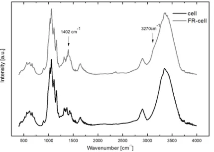
The FTIR spectra of the untreated (cell) and flame-retardant-treated cellulose fibres (FR-cell) are compared in Fig. 1. The presence of DAP on the surface of the FR-treated fibres was confirmed by the appearance of the characteristic bands at 1402 cm-1 and 3270 cm-1, both assigned to the vibrations of ammonium [29]. The small amount of BA absorbed on the surface of the cellulose fibres was not detectable by this method.
Fig. 1. FTIR spectra of untreated and FR-treated cellulose fibres
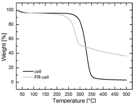
In Fig. 2, the effect of FR-treatment on the thermal degradation of cellulose can be followed. Due to the treatment with DAP and BA containing solution the initial decomposition temperature of cellulose was lowered by 50°C. The shift to lower temperature is typical for treatments with phosphates; in our previous works about 90°C lower onset temperatures of decomposition were measured both for ammonium-phosphate [30] and diammonium-phosphate-treated natural fibres [31]. It is presumed that in this case the early pyrolysis of the phosphate-treated cellulose was compensated by the addition of BA, which promoted the formation of a glassy film on the surface of the cellulose fibres [32] and thus increased their thermal stability by about 40°C compared to the phosphate-treated fibre, but still below that of the non-treated fibres. Nevertheless, the thermal decomposition of the FR- treated cellulose fibres starts at 235°C, which is higher than the typical processing temperature of PLA foams. On the other hand, the combined treatment with DAP and BS effectively promoted the formation of solid residues and char. The char amount at 500 °C for the FR-treated fibres was 36.5 %, while only 3.0% ash remained from the non-treated cellulose. Based on the significant char formation ability of the FR-treated fibres, advantageous effect was expected on the flame retardant properties of the FR-cellulose containing PLA foams.
Fig. 2. TGA curves of the non-treated (cell) and FR-treated cellulose fibres (FR-cell)
3.2 Morphology of the flame retarded PLA foams
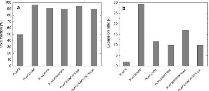
The void fraction and expansion ratio of the PLA foams, prepared by sc-CO2-aided extrusion foaming, are shown in Fig. 3. It can be seen that the additive-free PLA (PLA/CE) could be expanded only to its double volume, having approximately 50% void fraction. In the case of all the composite foams, however, microcellular foam structures with void fractions higher than 90% were obtained, presumably as a result of the increased melt viscosity and effective heterogeneous cell nucleation promoted by the used additives. Compared to the pure PLA foam (PLA/CE) significantly increased expansion ratios were achieved for all the additive containing foams, but the highest expansion ratio of 29.3 was achieved for the MMT containing FR-free foam (PLA/CE/MMT). These results are in connection with the heterogeneous nucleation ability of the used additives, which is in strong relation with the particle size; the nucleation effect of the larger size IFR and cellulose is moderate compared to that of the MMT nanoclays. Although the introduction of FR particles at higher loadings could noticeably hinder the foam expansion due to the reduced amount of polymer resin and increased stiffness of the polymer matrix [21,22], in our case an expansion ratio as high as 16.9 was reached for the PLA/CE/MMT/IFR/cell foam with 19.5% additive content.
Nevertheless, when FR-treated cellulose was added (PLA/CE/MMT/IFR/FR-cell), the expansion ratio decreased to 9.9, which is explained by the weak compatibility of FR-cell with the PLA matrix, causing increased number of interfacial defects, which favours the escape of CO2 during the foaming process.
Fig. 3. Void fraction (a) and expansion ratio (b) of the PLA foams
Fig. 4. SEM micrographs of the PLA foams (with ×500 amplification)
SEM images taken from the cross-sections of the PLA foams are presented in Fig. 4 and Fig. 5. In Fig. 4, the structure of PLA foams with the six different compositions are shown. Uniform, closed cellular foam structures can be observed, the average diameter of the cells is approximately 100-150 μm in all cases. As it was noticed based on the expansion ratio results (Fig. 3), PLA containing CE alone (Fig. 4 a) was not sufficiently foamable, instead of thin-walled cells, a coherent porous structure with low void fraction can be seen. Without the nucleating agent, slow crystallization and the absence of heterogeneous cell nucleation hindered the formation of high porosity foam structure. In the case of the PLA/CE/MMT foam (Fig. 4 b), uniform cell structure can be observed as an evidence of increased melt strength, effective cell nucleation and faster crystallization promoted by the incorporated MMT nanoparticles. The effect of the used FR agents on the morphology of the PLA foams was also examined. It was found that the larger size IFR particles themselves are less effective regarding heterogeneous nucleation, resulting in broader cell size distribution of the PLA/CE/IFR foam (Fig. 4 c). The addition of cellulose resulted in higher cell density (Fig. 4 e) and greater expansion ratio (see also in Fig. 3), however, with the FR-cell additive (Fig. 4 f) the structure of the foam became similar to that of the PLA/CE/MMT/IFR foam (Fig. 4 d) composed of slightly larger cells.
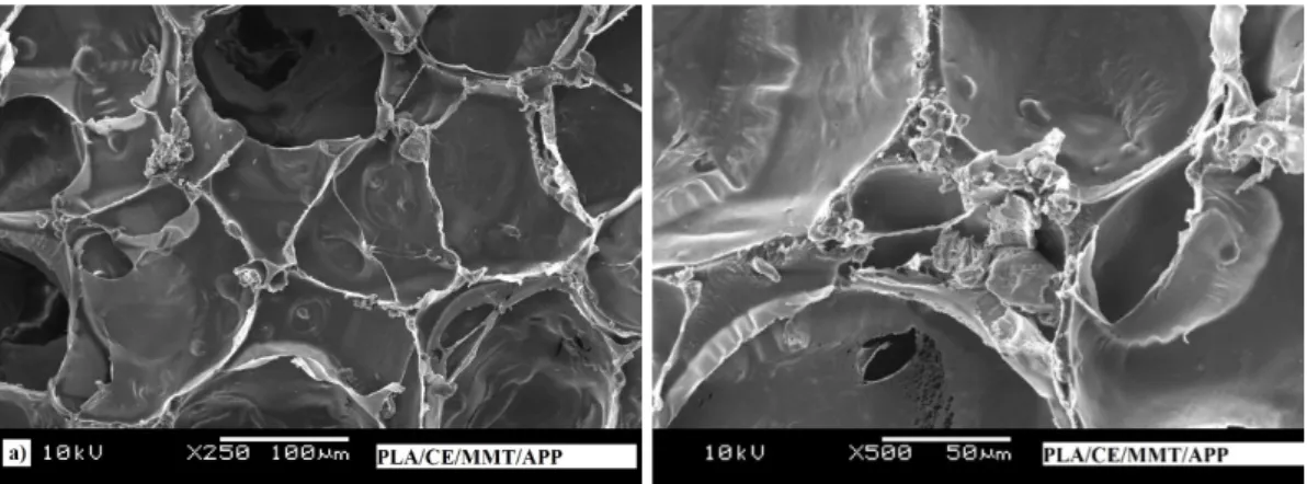
Fig. 5. SEM micrographs of the PLA/CE/MMT/IFR foam (×250, ×500)
As it can be seen from the SEM images presented in Fig. 5, the FR particles are well embedded in the PLA matrix material and they are mainly located in the cell wall junction regions. The high void fraction and expansion ratio values can be explained by the relatively thin cell walls and high cell density. It can be concluded that, despite the relatively high additive contents (almost 20 wt%), flame retarded PLA foams with adequate morphology could be manufactured by the extrusion foaming technology.
The distribution of the FR particles in the foamed samples was examined by EDS method. According to the micrographs presented in Fig. 6, the IFR additive system is well dispersed in the polymer matrix, the IFR particles with diameters of 10-30 µm can be identified with adequate distribution. The FR-treated cellulose particles (length of which was 8 µm) could not be distinguished from the PLA matrix this way since their elemental compositions are similar, and their mass fraction was only 3 m/m%.
Fig. 6. EDS mapping of PLA/CE/MMT/IFR/FR-cell foam
3.3 Thermal properties of the flame retarded PLA foams
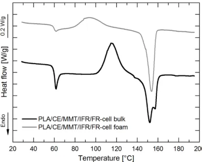
DSC analysis revealed that crystallization during the sc-CO2-assisted foaming process is fundamentally different from that of simple extrusion. As an example, in the thermograms of FR-cell containing bulk and foamed PLA samples (Fig. 7), glass transition temperature (Tg ~ 61°C), cold-crystallization temperature (Tcc) and melting temperature (Tm) can be examined. Concerning the curve of bulk PLA, a considerable cold-crystallization exotherm (Tcc ~110-130°C) can be observed alongside with two melting endothermic peaks at 152°C and 157°C corresponding to melting of the less ordered α’ and the thermodynamically more stable α crystals [8,33]. On the other hand, the foamed sample with same composition has much smaller exothermic peak in the range of 90-110°C and only one melting peak around 154°C, indicating higher crystallinity in the form of the ordered α crystals. The shift of cold- crystallization exotherm to lower temperature is attributed to the strain-induced nucleation enhanced crystallization of the stretched amorphous phase in the cell walls [34]. During foaming, PLA chains in the cell walls undergo significant bi-axial stretching, and when heated in the DSC, the crystallization of the aligned amorphous chains that did not crystallize during foaming is facilitated by the presence of the pre-existing crystals.
IMG1
30 µm 30 µm C K 30 µm P K 30 µm O K
100 µm
Fig. 7. DSC thermograms of FR-cell containing bulk and foamed PLA
The degree of crystallinity of the PLA blends before and after foaming was estimated and presented in Fig. 8. As it can be seen, the foams have significantly higher crystallinity then the bulk materials. It is mentioned in the literature [8] that cell expansion during the extrusion foaming process favours the formation of ordered crystals, and higher expansion ratio is accompanied with higher proportion of crystallinity. It is assumed that foaming of PLA blends causes chain orientation, and crystallinity is increased by strain-induced crystallization. The results showed that not only the MMT acts as nucleating agent, but the presence of IFR also promotes crystallization, furthermore, by adding neat or FR-treated cellulose, the foams’ crystallinity exceeded even 19%. Based on the enhanced crystallinity composed of the more stable α form, improved thermo-mechanical properties can be supposed for these foamed materials [35].
Fig. 8. Degree of crystallinity of the PLA blends before and after foaming
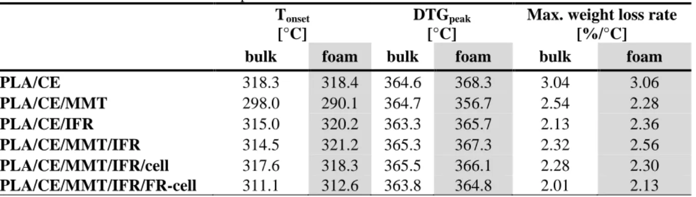
Characteristic parameters of TGA of the prepared PLA compounds before and after foaming are compared in Table 3 while the residual masses obtained at 500°C are shown in Fig. 9 (average value and standard deviation were determined from three repeated measurements). Based on the data of Table 3, it can be realized that the Tonset (initial degradation temperature) and DTGpeak (temperature of degradation rate maximum) of the foamed materials correlate with their expansion ratio (see in Fig. 3). Moderate expansion results in a slight shift to higher temperatures due to the lower heat conductivity (until the foamed structure exists). At much higher expansion ratio (samples PLA/CE/MMT and PLA/CE/MMT/IFR/cell), however, enhanced surface area is exposed to degradation, which process can overcome the delay caused by lower heat conductivity.
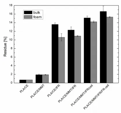
Based on the residual masses obtained at 500°C (Fig. 9) it can be seen that despite the identical FR contents, lower amount of char formed from the foamed samples. This is the consequence of the inhomogeneous distribution of the FR particles among the cells. As it was found during SEM examination (Fig. 5), the FR particles are aggregated mainly in the cell wall joints, while the thin cell walls are typically FR poor and therefore their charring cannot be initiated.
When considering the effect of the used additives on the thermal degradation, same tendencies can be observed for the bulk and foamed samples. MMT, when applied by itself (PLA/CE/MMT), caused slight decrease of the initial degradation temperature, but noticeably lowered the weight loss rate compared to the additive free reference samples (PLA/CE). The introduction of IFR further moderated the weight loss rate and effectively promoted the charring of the PLA samples, at 500°C more than 10% residue remained from all the IFR- containing samples (Fig. 9). The lowest maximal weight loss rate and the biggest residual mass were obtained, however, when FR-treated cellulose fibres were combined with the IFR system (PLA/CE/MMT/IFR/FR-cell). It is assumed that phosphorus and boron, being present right on the surface of cellulose, can initiate the charring and ceramisation of cellulose with high efficiency.
Table 3 TGA characteristic parameters of flame retarded PLA bulk and foamed materials Tonset
[°C]
DTGpeak
[°C]
Max. weight loss rate [%/°C]
bulk foam bulk foam bulk foam
PLA/CE 318.3 318.4 364.6 368.3 3.04 3.06
PLA/CE/MMT 298.0 290.1 364.7 356.7 2.54 2.28
PLA/CE/IFR 315.0 320.2 363.3 365.7 2.13 2.36
PLA/CE/MMT/IFR 314.5 321.2 365.3 367.3 2.32 2.56 PLA/CE/MMT/IFR/cell 317.6 318.3 365.5 366.1 2.28 2.30 PLA/CE/MMT/IFR/FR-cell 311.1 312.6 363.8 364.8 2.01 2.13
Fig. 9. Comparison of the residues of flame retarded bulk and foamed samples obtained at 500°C of TGA analyses performed in nitrogen atmosphere
3.4 Flammability characteristics of the flame retarded PLA foams
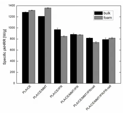
Pyrolysis combustion flow calorimetry (PCFC) was carried out on both the foamed and unfoamed flame retarded PLA samples. By this method, no significant difference could be evinced between the specific heat release rate (HRR) curves of the counterparts with identical composition. The evaluated specific peak of heat release rate (pkHRR) values are compared in Figure 10. Nevertheless, it can be seen that the specific pkHRR value of PLA/CE was effectively reduced by the applied IFR systems; the best result, about 40% reduction was achieved when MMT and cellulose were combined with the commercial IFR additive in the foamed and unfoamed samples alike. These results confirm the beneficial char promoting effect of the applied minor components of the flame retardant composition.
Figure 10. Specific pkHRR values of the flame retarded bulk and foamed samples obtained from PCFC measurements
Standard UL-94 tests and LOI measurements were performed to characterize the flame retardant performance of the prepared PLA foams also in comparison with that of the unfoamed samples with identical chemical composition. The results are shown in Table 4 and Fig. 11, respectively. The additive-free PLA foam (PLA/CE) with void fraction of about 50%
acted similarly to its unfoamed counterpart; horizontally mounted it burned with an average flame spreading rate of 39 mm/min and a LOI of 20.0 vol% was determined for this sample.
Thanks to the beneficial effect of MMT on the foaming process, highly porous structure (Vf= 96.6%) was obtained from the PLA/CE/MMT blend, the horizontal burning rate of which, however, became extremely rapid due to the readily available oxygen within the foam and failed the UL-94 test. On the contrary, the LOI of this foam sample increased to 24.0 vol%, the same value as that of its unfoamed counterpart. It is presumed that during LOI measurement, where the vertically mounted specimen is ignited from the top, the char promoting effect of MMT prevails over the fire feeding effect of the accelerated oxygen supply [36]. This means that MMT has multifunctional role in this system; it acts both as nucleating agent and flame retardant component. IFR content of 15% proved to be sufficient to pass V-0 classification according to the UL-94 standard for both types of samples, and to reach a LOI as high as 29.0 and 30.0 vol%, respectively.
In accordance with the literature [14,15], the combined application of MMT and IFR proved to be advantageous in both systems and resulted in increase of the LOI values, but the efficiency of the synergism proved to be moderate in the foamed samples. Despite the identical chemical composition, 9-10 vol% higher LOI values were reached in the case of the bulk materials than for the foamed samples containing both IFR and MMT additives. Zhai et al. also found that the foaming process reduces the LOI values of flame retarded PLA, which they attributed to two reasons; the increased contact area between PLA matrix and air and the decreased volume concentration of the used flame retardants in the expanded foam structures [21,22]. Interestingly, in our work significant differences between the LOI values of the foamed and unfoamed samples were only evidenced when both IFR and MMT were applied.
It is presumed that essential congregation of the MMT plates on the charring surface can
occur only in the case of the bulk samples, while the barrier effect of the nanoclay particles being concentrated in the cell wall joints cannot prevail.
When the effect of cellulose, applied as cost-effective filler with reinforcing potential, is evaluated, it can be seen that the LOI of the cellulose containing samples increased further.
The introduction of 3 wt% FR-cell led to 31.5 vol% LOI value of the foamed specimens. The flame retardant properties achieved in the case of the extruded PLA foams with high foam expansion ratios (Φ=16.9 and 9.9) noticeably outperform the flammability test results (LOI=
26.4%) published by Zhai et al. [21] on solid state foamed PLA foams with similar flame retardant composition (15% nitrogen and phosphorus containing FR + 3% starch) but lower expansion ratio. The increased expansion ratio and better flame retardant performance of the extruded foams can be ascribed probably to the dissimilar distribution of the FR particles compared to the solid state foamed samples. During extrusion, the foaming occurs at higher temperature coupled with continuous mixing, therefore the arrangement of FR particles and fillers in the polymer melt occurs simultaneously with the cell growth. As a result, significant part of the FR particles will be located in the cell wall joints (as observed in Fig. 5) where the major part of the polymer mass is present. The more FR particles are well embedded in the polymer matrix, the less is the possibility for interfacial debonding and formation of microholes enabling gas escape. In the case of the lower temperature solid state foaming technology, however, the inherent FR distribution within the polymer matrix does not remarkably change during cell growth, consequently more microholes will be induced at the filler-matrix interfaces, especially at the thin cell walls, hindering the cell growing ability and resulting in increased open-cell ratio accompanied with decreased expansion ratio.
Nevertheless, Zhai et al. also reported that with increasing foaming temperature (to 80°C) the cell structure of flame retardant loaded PLA foams, prepared by solid state foaming, became more uniform [22]. Similar conclusions can be drawn regarding the flame retardant properties; considering the morphology of the extruded foams, for the well embedded FR particles at the cell wall joints more polymer mass is available to be affected and thus better flame retardant efficiency can be observed. In this sense, it could be concluded that in the case of polymer foams, surprisingly, the special (in the cell wall joints) aggregated structure of the active fillers is favourable over their homogeneous distribution.
Table 4 UL94 rating of the prepared PLA foams
Sample UL-94
[rating]
bulk foam
PLA/CE HB* (31) HB* (39)
PLA/CE/MMT HB* (33) NR* (313)
PLA/CE/IFR V-0 V-0
PLA/CE/MMT/IFR V-0 V-0
PLA/CE/MMT/IFR/cell V-0 V-0
PPLA/CE/MMT/IFR/FR-cell V-0 V-0
*in parenthesis the flame spreading rates [mm/min] are indicated
Fig. 11. LOI values of the prepared flame retarded bulk and foamed samples
4 Conclusions
Flame retarded microcellular PLA foams were successfully manufactured by sc-CO2- assisted extrusion foaming technology. During production, CE was used to improve the rheological behaviour and MMT was applied as nucleating agent for better foamability and as potential FR synergist at the same time. In spite of the fact that foams are more flammable than their solid polymeric counterparts, significant flame retardancy was achieved by incorporating APP based IFR additive in the cellular structure. The efficiency of the IFR was enhanced by combining it with FR-treated cellulose fibres, which noticeably increased the charring ability of the system, as revealed by the TGA results and PCFC measurements. As a result, 40% reduction in specific peak of heat release rate, UL94 V-0 rating accompanied with LOI value as high as 31.5 vol% were reached for the IFR and FR-cell containing PLA foam.
Also, among the examined foams, the highest degree of crystallinity reached 19%, composed of the more stable α form, indicating nucleating effect of the used bio-based charring agent.
The prepared flame retarded biocomposite foams could potentially find application as cushion packaging for electronics or airline industry.
Supercritical CO2-aided extrusion resulted in low-density foams having void fractions higher than 90% accompanied with expansion ratios of 10-20, depending on the filler-matrix compatibility even at relatively high (almost 20 wt%) additive contents. SEM images revealed that the effectively flame retarded PLA foams have uniform cellular structure with characteristic cell diameters of 100-150 μm. Major part of the FR particles was found to be embedded in the cell wall joints, which is of key importance regarding expandability and charring ability. From this respect, extrusion foaming was found to be favorable compared to the batch technologies due to the continuous mixing of the components and the typically higher temperature applied during foam forming, which allows the active fillers to allocate in the polymer melt simultaneously with the cell growth. As a result, fewer microholes will be induced at the filler-matrix interfaces in the thin cell walls, and thus lower open-cell ratios and higher expansion ratios can be obtained. Considering the flame retardant properties, more
polymer is available for the well-embedded active fillers, located in the cell wall joints, to be affected and thus enhanced char forming and improved flame retardant properties can be obtained.
5 Acknowledgement
The research was financially supported by the Hungarian Scientific Research Fund (OTKA K112644 and PD121171). This work was supported by the National Research, Development and Innovation Fund in the frame of NVKP_16-1-2016-0012 and GINOP-2.2.1-15-2016- 00015 projects. K. Bocz is thankful for the János Bolyai Research Scholarship of the Hungarian Academy of Sciences.
6 References
[1] M. Niaounakis: Biopolymers: Processing and Products. Plastics Design Library (PDL) Handbook Series 2015;327
[2] Pilla S, Kim SG, Auer GK, Gong S, Park CB. Microcellular extrusion-foaming of polylactide with chain-extender. Polym Eng Sci 2009;49:1653–1660
[3] Parker K, Garancher J-P, Shah S, Weal S, Fernyhough A. Polylactic acid (PLA) foams for packaging applications. In: Pilla S (eds). The handbook of bioplastics and biocomposites engineering pplications, Hoboken, N.J.: John Wiley & Sons Inc., 2011;161–175.
[4] Wang J, Zhu W, Zhang H, Park CB. Continuous processing of low-density, microcellular poly(lactic acid) foams with controlled cell morphology and crystallinity.
Chem Eng Sci 2012;75:390–399
[5] Nofar M. Effects of nano-/micro-sized additives and the corresponding induced crystallinity on the extrusion foaming behavior of PLA using supercritical CO2. Mater Des 2016;101:24–34
[6] Nofar M, Park CB. Heterogeneous Cell Nucleation Mechanisms in Polylactide Foaming. In: Biofoams: Science and Applications of Bio-based Cellular and Porous Materials, Boca Raton, FL: CRC Press, 2015;153-174
[7] Keshtkar M, Nofar M, Park CB, Carreau PJ. Extruded PLA/clay nanocomposite foams blown with supercritical CO2. Polymer 2014;55:4077-4090
[8] Bocz K, Tábi T, Vadas D, Sauceau M, Fages J, Marosi Gy. Characterisation of natural fibre reinforced PLA foams prepared by supercritical CO2 assisted extrusion.
Express Polym Lett 2016;10:771-779
[9] Fontaine G, Bourbigot S. Intumescent polylactide: a nonflammable material. J Appl Polym Sci 2009;113:3860–3865
[10] Ding Y, McKinnon MB, Stoliarov SI, Fontaine G, Bourbigot S. Determination of kinetics and thermodynamics of thermal decomposition for polymers containing reactive flame retardants: Application to poly(lactic acid) blended with melamine and ammonium polyphosphate. Polym Degrad Stabil 2016;129:347–362
[11] Feng C, Liang M, Jiang J, Huang J, Liu H. Flame retardant properties and mechanism of an efficient intumescent flame retardant PLA composites. Polym Adv Technol 2016;27:693-700
[12] Hapuarachchi TD, Peijs T. Multiwalled carbon nanotubes and sepiolite nanoclays as flame retardants for polylactide and its natural fibre reinforced composites.
Composites Part A, 2010;41(8):954-963
[13] Tang G, Deng D, Chen J, Zhou K, Zhang H, Huang X, Zhou Z. The influence of organo-modified sepiolite on the flame-retardant and thermal properties of intumescent flame-retardant polylactide composites. J Therm Anal Calorim 2017;130.763-772 [14] Li S, Yuan H, Yu T, Yuan W, Ren J. Flame-retardancy and anti-dripping effects of intumescent flame retardant incorporating montmorillonite on poly(lactic acid). Polym Adv Technol, 2009;20:1114–1120
[15] Bocz K, Domonkos M, Igricz T, Kmetty Á, Bárány T, Marosi G. Flame retarded self-reinforced poly(lactic acid) composites of outstanding impact resistance. Compos Part A Appl Sci and Manuf 2015;70:27–34
[16] Li S, Yuan H, Yu T, Yuan W, Ren J. Flame-retardancy and anti-dripping effects of intumescent flame retardant incorporating montmorillonite on poly (lactic acid).
Polymer Adv Techn 2009;20:1114-1120
[17] Isitman NA, Kaynak C. Nanostructure of montmorillonite barrier layers: a new insight into the mechanism of flammability reduction in polymer nanocomposites.
Polym Degrad Stabil 2011;96:2284-2289
[18] Pack S, Bobo E, Muir N, Yang K, Swaraj S, Ade H, Cao C, Korach CS, Kashiwagi T, Rafailovich MH. Engineering biodegradable polymer blends containing flame retardant-coated starch/nanoparticles. Polymer 2012;53:4787-4799
[19] Gaan S, Sun G. Effect of phosphorus flame retardants on thermo-oxidative decomposition of cotton. Polym Degrad Stab 2007;92:968-974
[20] Grexa O, Lübke H. Flammability parameters of wood tested on a cone calorimeter.
Polym Degrad Stab 2001;74:427–432
[21] Wang J, Ren Q, Zheng W, Zhai W. Improved Flame-Retardant Properties of Poly(lactic acid) Foams Using Starch as a Natural Charring Agent. Ind Eng Chem Res 2014;53:1422-1430
[22] Wang K, Wang J, Zhao D, Zhai W. Preparation of microcellular poly(lactic acid) composites foams with improved flame retardancy. J Cell Plast 2016;22:1-19
[23] Sauceau M, Fages J, Common A, Nikitine C, Rodier E. New challenges in polymer foaming: A review of extrusion processes assisted by supercritical carbon dioxide. Prog Polym Sci 2011;36:749-766
[24] NatureWorks: Ingeo™ Biopolymer 3052D Technical Data Sheet (2011, last viewed: 2017)
http://www.natureworksllc.com/~/media/Technical_Resources/Technical_Data_Sheets /TechnicalDataSheet_3052D_injection-molding_pdf.pdf
[25] Clariant – Products – Exolit® AP 462: Specifications (2014, last viewed: 2017) http://www.clariant.com/en/Solutions/Products/2014/03/18/16/31/Exolit-AP-462 [26] Cloisite Technical Data Sheet (2013, last viewed: 2017)
https://www.byk.com/en/additives/additives-by-name/cloisite-116.php
[27] Fischer EW, Sterzel HJ, Wegner G. Investigation of the structure of solution grown crystals of lactide copolymers by means of chemical reactions. Colloid Polym Sci, 1973;251:980–990
[28] Ramgobin A, Fontaine G, Penverne C, Bourbigot S. Thermal stability and fire properties of salen and metallosalens as fire retardants in thermoplastic polyurethane (TPU). Materials, 2017; 10:665
[29] Suardana NPG, Ku MS, Lim JK. Effects of diammonium phosphate on the flammability and mechanical properties of bio-composites. Mater Des 2011;32:1990–
1999
[30] Bocz K, Szolnoki B, Wladyka-Przybylak M, Bujnowicz K, Harakály Gy, Bodzay B, et al. Flame retardancy of biocomposites based on thermoplastic starch. Polimery 2013;58:385-394
[31] Bocz K, Szolnoki B, Marosi A, Tábi T, Wladyka-Przybylak M, Marosi Gy. Flax fibre reinforced PLA/TPS biocomposites flame retarded with multifunctional additive system. Polym Degrad Stabil, 2014;106:63-73
[32] Nussbaum RM. The Effect of Low Concentration Fire Retardant Impregnations on Wood Charring Rate and Char Yield. J Fire Sci 1988;6:290-306
[33] Le Marec PE, Ferry L, Quantin JC, Benezet JC, Bonfils F, Guilbert S, Bergeret A.
Influence of melt processing conditions on poly(lactic acid) degradation: Molar mass distribution and crystallization. Polym Degrad Stabil 2014;110:353-363
[34] Garancher JP, Fernyhough A. Expansion and dimensional stability of semi- crystalline polylactic acid foams. Polym Degrad Stab 2014;100:21-28
[35] Battegazzore D, Bocchini S, Frache A. Crystallization kinetics of poly(lactic acid)- talc composites. Express Polym Lett 2011;5:849–858
[36] Modesti M, Lorenzetti A. FR design for foam materials. In: Wilkie CA, Morgan AB. (eds). Fire Retardancy of Polymeric Materials, Second Edition J Boca Raton, FL:
CRC Press, 2009;763-777