Improved Model for Indoor Propagation Loss in the 5G FR2 Frequency Band
MARCH 2021 • VOLUME XIII • NUMBER 1 2
INFOCOMMUNICATIONS JOURNAL
1,2Department of Broadband Infocommunications and Electromagnetic Theory, Budapest University of Technology and Economics, Hungary.
1 (e-mail: makara.arpadlaszlo@edu.bme.hu)
2 (e-mail: csurgai-horvath.laszlo@vik.bme.hu)
Improved Model for Indoor Propagation Loss in the 5G FR2 Frequency Band
Árpád László Makara1 and László Csurgai-Horváth2
DOI: 10.36244/ICJ.2021.1.1
> REPLACE THIS LINE WITH YOUR PAPER IDENTIFICATION NUMBER (DOUBLE-CLICK HERE TO EDIT) < 1
Abstract—One of the latest developments today is the 5G, or 5th generation mobile network. In addition to a number of innovations, the new system also includes millimeter-wavelength frequency ranges denoted with FR2, that formerly not applied for these specific purposes. Proper management of the transmitter and receiver antenna beams is required for efficient communication in this frequency range. For future use, the simplest implementation way is electronically shaping the antenna beams by an algorithm to orient the antennas in the best possible direction. The prerequisites for these algorithms are appropriate propagation models, which are currently lacking, and those that publicly available are not accurate enough for practical use.
Due to its complexity, solving this task is expected to be feasible only with artificial intelligence based solutions that require large amounts of input data for training. This amount of data requires long-term measurement data, which is not a feasible solution considering the rate of development. There are two possible ways to solve this: creating more accurate propagation models or apply simulations. For the latter solutions, it may also be necessary to validate based on measurement results and models.
In this paper we provide an overview of the wave propagation conditions in the new FR2 frequency range in the case of indoor use, intending to create an accurate propagation model. We present the existing models in other fields of applications and the typical propagation conditions in these bands in view of the existing research in this area. By analyzing the measurements performed at the department, we point out the shortcomings of the previous models and the parameters to be taken into account.
Then we present an improved model based on the ITU recommendation for indoor propagation.
Index Terms—5G, environmental coefficient, FR2 band, indoor propagation, path loss model
I. INTRODUCTION
HE next generation of wireless networks is the 5th generation mobile network, for which some of the standards are still being developed today. The need to develop a new system is caused by the drastic increase in consumer demand [1], based on current trends. The number of devices on the network simultaneously is continuously growing, requiring a faster and higher capacity network creation.
With regard to the standardization processes, it is worth saying a few words about the bigger and more significant organizations. The 3GPP (3rd Generation Partnership Project) umbrella organization brings together the various
1,2Department of Broadband Infocommunications and Electromagnetic Theory, Budapest University of Technology and Economics, Hungary
standardization processes of mobile communication. The ITU is the UN specialized agency whose task is international facilitating telecommunications cooperation. In this work, IMT-2020 (International Mobile Telecommunications-2020) standard was the guideline for specifications and standards [2].
A. 5G system requirements
In 5G a number of new uses are planned, based on past trends [1]. With the new system for wireless connections in existing areas a drastic increase in speed would be achievable. Without wishing to be exhaustive, the main areas of application are: [2]:
Support for real time video calls.
High-speed data connection support (50 MB/s or higher).
Serving high-speed users (up to 500 km/hr).
IoT support (such as wireless operation of sensor networks).
Ultra-reliable communications (URC).
Massive machine type communications (mMTMC).
Enhanced mobile broadband (eMBB).
In fact, to meet user needs (existing and future) requirements for the 5G network [3], assumed increasing number of assets necessitated the designation of new frequency bands as listed in Table I:
The new frequency bands used previously only for satellite- to-Earth communications or in the access network of the mobile communications system. The characteristics of these new domains are different for mobile communication bands so far used, so their empirical description is particularly important for implementation.
B. The frequency range examined
One of the many designated frequency bands is 38 GHz (and vicinity), which is the main subject of this paper. However, the
E-mail: csurgai-horvath.laszlo@vik.bme.hu
Improved Model for Indoor Propagation Loss in the 5G FR2 Frequency Band
Árpád László Makara1, László Csurgai-Horváth2
T
TABLEI 5GREQUIREMENTS User data speed Downlink: 100 Mbps - 1 Gbps
Uplink: 50 Mbps - 500Mbps Maximal data speed Downlink:20 Gbps; Uplink: 10 Gbps Bandwidth 100 MHz – 1 GHz
Mobility Up to 500 km/hr
Delay Ultra-Reliable and Low Latency Communications: 0.5 ms Enhanced Mobile BroadBand: 4 ms Connections density 250.000 user/km2
Local traffic capacity 15 Mbps/m2
> REPLACE THIS LINE WITH YOUR PAPER IDENTIFICATION NUMBER (DOUBLE-CLICK HERE TO EDIT) < 2 statements made are similar to the other higher frequency
ranges. The signal propagation in the investigated band has a different nature than the traditional lower frequencies. In addition, it is no longer negligible that solid bodies are also have significant attenuation effect [4]. Among other things, this is why we can talk about different indoors and outdoors models.
In such a high frequency range, the transmitter and receiver antenna beam orientations are particularly critical [5] for good reception conditions, in fact, for as long as a device is connected to the network. In many application areas the receiver moves relative to the transmitter while connected to the network. But even if both the transmitter and the receiver are in a constant, fixed position, a change can and will happen in the space between them. For all these reasons, it is essential that at least in the receiver, be able to control the antenna beam, thus provide better reception conditions [6]. However, the time required for control should be as short as possible, regardless of outdoor or indoor use, and no user can feel that there is significant fluctuation in the received signal level.
Summarizing all this, it becomes necessary to change the operational environment as quickly as possible by adaptive beamforming, in order to maximize the transmitter and receiver antenna directing at each other, over the entire range of operating time. The beamforming control must be such that the user does not take anything from it and the quality of service also meets the expectations.
The complexity of the task is predicted to require an adaptive beamformer solution based on artificial intelligence algorithms in the future application of higher frequency ranges. With all this, the goal is to ultimately produce a model with which the necessary beamforming algorithms will be trainable for future use.
C. The structure of the paper
In Section 2, we present the frequency ranges of the 5G radio interface. Following this, in Section 3, we describe the various public propagation models, highlighting them separately the one that is best used for our purpose.
After all, we will briefly summarize how the department developed the competence required for the task in Section 4 and what tools are available to us to perform the measurements.
Next, in Section 5, we analyze the completed measurements and compare these results with the relevant models and show what further steps are taken necessary for the end use. Finally, in Section 6, we present a new model designed to facilitate adaptive beamforming based on the experience shared in the previous chapters.
II. 5GFREQUENCY BANDS AND THEIR CHARACTERISTICS 5G NR (Abbreviation for 5G New Radio) [8] stands for layer radio access technology (standard abbreviation: RAT) [9]. The 5G NR defines two frequency bands, and several within subbands:
Frequency Range 1 (FR1): Bands below 6 GHz
Frequency Range 2 (FR2): Between 24.25 and 52.5 GHz There are also currently plans to expand the FR1 range to
410 MHz and 7125 MHz and that, in the case of FR2, bands up to 100 GHz should be established. How much bandwidth will eventually be needed will be determined by the user needs.
In 2018, the n260 has already been allocated for use in the US (among other things) [10]. In the case of Hungary, during 2019 they were only allocated in FR1 bands for the operation of 5G [11]. The mobile service providers that have won these bands are already advertised as an available service.
This paper covers the frequency range of 38 GHz and surrounding in the FR2 band for a more thorough examination.
A. Path loss in FR2 frequency bands
When using 5G, the radio waves will in most cases propagate in the air, respectively sometimes through walls, objects, but ultimately in a dominant path in open space. The relative dielectric constant of air is the function of frequency, temperature, pressure and humidity [12] (only the very first parameter has an actual influence). For outdoor use, this means that this frequency band is already highly exposed to the weather [14]. From a practical application point of view, the attenuation of the medium will change, which will be proportional to the distance [12].
Another significant factor besides attenuation is the occurrence of reflections (related to even the issue of transmission, but this is now secondary). The electromagnetic wave reflected at a certain percentage at the medium boundary.
The degree of reflections is basically affected by material properties or the frequency, while the physical size of the reflecting object must be larger than the wavelength.
It is important to talk about interference on the topic of reflections. Interference occurs when two or more waves meet and their phases are different. We can speak of constructive or destructive interference, depending on whether the amplitude of the wave (signal) will be larger or smaller than it was originally. Where there is reflection, there is a high chance of interference that is greater it is likely to be destructive rather than constructive.
B. Uses of the 38 GHz band to date
The department has former experience with this frequency band for Alphasat (Inmarsat-4A F4) [15] to communicate with a satellite and during these the main propagation characteristics were examined. A feature of this application is that the exact position of the satellite is always known, so the antennas are directed at each other without any particularly great obstacle in the path. The most important factor of the mode of use is the individual antennas orientation [5]. In terms of practical implementation, it is typically narrow in direction antennas with high gain are used.
In addition to satellite reception, the department has previously conducted a shorter research on 38 GHz band. In 2018 [7] we examined how behave electromagnetic waves at this frequency indoors, including in cases when antenna orientation to each other was not ensured. Measurements related to the project results were compared with ITU-R Recommendation P.1238 [16], during which it is concluded that the recommended model gives an acceptable result as long as
Improved Model for Indoor Propagation Loss in the 5G FR2 Frequency Band INFOCOMMUNICATIONS JOURNAL
MARCH 2021 • VOLUME XIII • NUMBER 1 3
> REPLACE THIS LINE WITH YOUR PAPER IDENTIFICATION NUMBER (DOUBLE-CLICK HERE TO EDIT) < 2 statements made are similar to the other higher frequency
ranges. The signal propagation in the investigated band has a different nature than the traditional lower frequencies. In addition, it is no longer negligible that solid bodies are also have significant attenuation effect [4]. Among other things, this is why we can talk about different indoors and outdoors models.
In such a high frequency range, the transmitter and receiver antenna beam orientations are particularly critical [5] for good reception conditions, in fact, for as long as a device is connected to the network. In many application areas the receiver moves relative to the transmitter while connected to the network. But even if both the transmitter and the receiver are in a constant, fixed position, a change can and will happen in the space between them. For all these reasons, it is essential that at least in the receiver, be able to control the antenna beam, thus provide better reception conditions [6]. However, the time required for control should be as short as possible, regardless of outdoor or indoor use, and no user can feel that there is significant fluctuation in the received signal level.
Summarizing all this, it becomes necessary to change the operational environment as quickly as possible by adaptive beamforming, in order to maximize the transmitter and receiver antenna directing at each other, over the entire range of operating time. The beamforming control must be such that the user does not take anything from it and the quality of service also meets the expectations.
The complexity of the task is predicted to require an adaptive beamformer solution based on artificial intelligence algorithms in the future application of higher frequency ranges. With all this, the goal is to ultimately produce a model with which the necessary beamforming algorithms will be trainable for future use.
C. The structure of the paper
In Section 2, we present the frequency ranges of the 5G radio interface. Following this, in Section 3, we describe the various public propagation models, highlighting them separately the one that is best used for our purpose.
After all, we will briefly summarize how the department developed the competence required for the task in Section 4 and what tools are available to us to perform the measurements.
Next, in Section 5, we analyze the completed measurements and compare these results with the relevant models and show what further steps are taken necessary for the end use. Finally, in Section 6, we present a new model designed to facilitate adaptive beamforming based on the experience shared in the previous chapters.
II. 5GFREQUENCY BANDS AND THEIR CHARACTERISTICS 5G NR (Abbreviation for 5G New Radio) [8] stands for layer radio access technology (standard abbreviation: RAT) [9]. The 5G NR defines two frequency bands, and several within subbands:
Frequency Range 1 (FR1): Bands below 6 GHz
Frequency Range 2 (FR2): Between 24.25 and 52.5 GHz There are also currently plans to expand the FR1 range to
410 MHz and 7125 MHz and that, in the case of FR2, bands up to 100 GHz should be established. How much bandwidth will eventually be needed will be determined by the user needs.
In 2018, the n260 has already been allocated for use in the US (among other things) [10]. In the case of Hungary, during 2019 they were only allocated in FR1 bands for the operation of 5G [11]. The mobile service providers that have won these bands are already advertised as an available service.
This paper covers the frequency range of 38 GHz and surrounding in the FR2 band for a more thorough examination.
A. Path loss in FR2 frequency bands
When using 5G, the radio waves will in most cases propagate in the air, respectively sometimes through walls, objects, but ultimately in a dominant path in open space. The relative dielectric constant of air is the function of frequency, temperature, pressure and humidity [12] (only the very first parameter has an actual influence). For outdoor use, this means that this frequency band is already highly exposed to the weather [14]. From a practical application point of view, the attenuation of the medium will change, which will be proportional to the distance [12].
Another significant factor besides attenuation is the occurrence of reflections (related to even the issue of transmission, but this is now secondary). The electromagnetic wave reflected at a certain percentage at the medium boundary.
The degree of reflections is basically affected by material properties or the frequency, while the physical size of the reflecting object must be larger than the wavelength.
It is important to talk about interference on the topic of reflections. Interference occurs when two or more waves meet and their phases are different. We can speak of constructive or destructive interference, depending on whether the amplitude of the wave (signal) will be larger or smaller than it was originally. Where there is reflection, there is a high chance of interference that is greater it is likely to be destructive rather than constructive.
B. Uses of the 38 GHz band to date
The department has former experience with this frequency band for Alphasat (Inmarsat-4A F4) [15] to communicate with a satellite and during these the main propagation characteristics were examined. A feature of this application is that the exact position of the satellite is always known, so the antennas are directed at each other without any particularly great obstacle in the path. The most important factor of the mode of use is the individual antennas orientation [5]. In terms of practical implementation, it is typically narrow in direction antennas with high gain are used.
In addition to satellite reception, the department has previously conducted a shorter research on 38 GHz band. In 2018 [7] we examined how behave electromagnetic waves at this frequency indoors, including in cases when antenna orientation to each other was not ensured. Measurements related to the project results were compared with ITU-R Recommendation P.1238 [16], during which it is concluded that the recommended model gives an acceptable result as long as
> REPLACE THIS LINE WITH YOUR PAPER IDENTIFICATION NUMBER (DOUBLE-CLICK HERE TO EDIT) < 2 statements made are similar to the other higher frequency
ranges. The signal propagation in the investigated band has a different nature than the traditional lower frequencies. In addition, it is no longer negligible that solid bodies are also have significant attenuation effect [4]. Among other things, this is why we can talk about different indoors and outdoors models.
In such a high frequency range, the transmitter and receiver antenna beam orientations are particularly critical [5] for good reception conditions, in fact, for as long as a device is connected to the network. In many application areas the receiver moves relative to the transmitter while connected to the network. But even if both the transmitter and the receiver are in a constant, fixed position, a change can and will happen in the space between them. For all these reasons, it is essential that at least in the receiver, be able to control the antenna beam, thus provide better reception conditions [6]. However, the time required for control should be as short as possible, regardless of outdoor or indoor use, and no user can feel that there is significant fluctuation in the received signal level.
Summarizing all this, it becomes necessary to change the operational environment as quickly as possible by adaptive beamforming, in order to maximize the transmitter and receiver antenna directing at each other, over the entire range of operating time. The beamforming control must be such that the user does not take anything from it and the quality of service also meets the expectations.
The complexity of the task is predicted to require an adaptive beamformer solution based on artificial intelligence algorithms in the future application of higher frequency ranges. With all this, the goal is to ultimately produce a model with which the necessary beamforming algorithms will be trainable for future use.
C. The structure of the paper
In Section 2, we present the frequency ranges of the 5G radio interface. Following this, in Section 3, we describe the various public propagation models, highlighting them separately the one that is best used for our purpose.
After all, we will briefly summarize how the department developed the competence required for the task in Section 4 and what tools are available to us to perform the measurements.
Next, in Section 5, we analyze the completed measurements and compare these results with the relevant models and show what further steps are taken necessary for the end use. Finally, in Section 6, we present a new model designed to facilitate adaptive beamforming based on the experience shared in the previous chapters.
II. 5GFREQUENCY BANDS AND THEIR CHARACTERISTICS 5G NR (Abbreviation for 5G New Radio) [8] stands for layer radio access technology (standard abbreviation: RAT) [9]. The 5G NR defines two frequency bands, and several within subbands:
Frequency Range 1 (FR1): Bands below 6 GHz
Frequency Range 2 (FR2): Between 24.25 and 52.5 GHz
410 MHz and 7125 MHz and that, in the case of FR2, bands up to 100 GHz should be established. How much bandwidth will eventually be needed will be determined by the user needs.
In 2018, the n260 has already been allocated for use in the US (among other things) [10]. In the case of Hungary, during 2019 they were only allocated in FR1 bands for the operation of 5G [11]. The mobile service providers that have won these bands are already advertised as an available service.
This paper covers the frequency range of 38 GHz and surrounding in the FR2 band for a more thorough examination.
A. Path loss in FR2 frequency bands
When using 5G, the radio waves will in most cases propagate in the air, respectively sometimes through walls, objects, but ultimately in a dominant path in open space. The relative dielectric constant of air is the function of frequency, temperature, pressure and humidity [12] (only the very first parameter has an actual influence). For outdoor use, this means that this frequency band is already highly exposed to the weather [14]. From a practical application point of view, the attenuation of the medium will change, which will be proportional to the distance [12].
Another significant factor besides attenuation is the occurrence of reflections (related to even the issue of transmission, but this is now secondary). The electromagnetic wave reflected at a certain percentage at the medium boundary.
The degree of reflections is basically affected by material properties or the frequency, while the physical size of the reflecting object must be larger than the wavelength.
It is important to talk about interference on the topic of reflections. Interference occurs when two or more waves meet and their phases are different. We can speak of constructive or destructive interference, depending on whether the amplitude of the wave (signal) will be larger or smaller than it was originally. Where there is reflection, there is a high chance of interference that is greater it is likely to be destructive rather than constructive.
B. Uses of the 38 GHz band to date
The department has former experience with this frequency band for Alphasat (Inmarsat-4A F4) [15] to communicate with a satellite and during these the main propagation characteristics were examined. A feature of this application is that the exact position of the satellite is always known, so the antennas are directed at each other without any particularly great obstacle in the path. The most important factor of the mode of use is the individual antennas orientation [5]. In terms of practical implementation, it is typically narrow in direction antennas with high gain are used.
In addition to satellite reception, the department has previously conducted a shorter research on 38 GHz band. In 2018 [7] we examined how behave electromagnetic waves at this frequency indoors, including in cases when antenna orientation to each other was not ensured. Measurements related to the project results were compared with ITU-R Recommendation P.1238 [16], during which it is concluded that
> REPLACE THIS LINE WITH YOUR PAPER IDENTIFICATION NUMBER (DOUBLE-CLICK HERE TO EDIT) < 3 antenna orientation towards each other is ensured.
III. EXISTING PROPAGATION MODELS
The models can be divided into three large groups: indoor, outdoor and free space. In addition we can distinguish between empirical, deterministic, and semi-empirical models.
For empirical models a correlation based on a statistical approach can be given. Easily and are quick to use, in return they are not always the most accurate. In a deterministic case based on some preliminary model, the propagation in the given space is calculated to get the quantity sought.
For mobile communication networks, outdoor and indoor models are important, however, outdoor propagation models can also be used for a kind of control (but these are best for point-to-point connections in particular).
The number of models dedicated to this frequency band is very low in the literature. Due to the nature of the problem, deterministic modelling methods are accurate but require more computing capacity, while the ray-tracing methods can be used along affordable computational capacities [13].
From end use, it follows that we want to perform as few calculations as possible in order to get results as soon as possible. In this paper, we deal only with the examination of empirical models.
A. Free-space propagation
In the case of outdoor propagation, most models assume direct vision or other special circumstances. The attenuation per unit length thus calculated is typically lower as for indoor propagation models, but of a similar order of magnitude [17].
Hence an estimate can be used in indoor modelling (taking into account its limitations). The most common such relationship, which we simply refer to as outdoor attenuation hereinafter [21]
takes the following form:
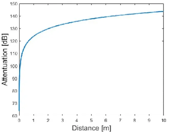
𝑃𝑃𝐿𝐿= 20 ∙ log10(𝑑𝑑) + 20 ∙ log10(𝑓𝑓) + 92.45 (1) where dis the distance in kilometres,fis the frequency in GHz, and the result is given in decibels and describes the outdoor attenuation between isotropic antennas in vacuum. Once the medium in which the wave propagates is already air, additional attenuation occurs up. For low distances Fig. 1. depicts the path loss calculated with Equation (1).
B. Close-in free space reference distance path loss model The Close-in free space reference distance path loss model [22] (hereinafter CI) is a reference model based on outdoor propagation and it is applied for comparison multiple indoor signal propagation results:
𝑃𝑃𝐿𝐿(𝐶𝐶𝐶𝐶)= FSPL(𝑓𝑓, 𝑑𝑑0) + 10 ⋅ 𝑛𝑛 ⋅ log10(𝑑𝑑
𝑑𝑑0) + 𝑋𝑋σ𝐶𝐶𝐶𝐶 (2) where FSPL(f,d0)is the outdoor attenuation at the reference distance (d0is 1 meter) at the given frequency fmeasured in GHz,nis the path loss factor (PLE) and XσCIis a zero-valued Gaussian random variable with σ standard deviation. The measured PLE [23] coefficients found in the literature are largely the same in the ITU model of indoor signal propagation with distance-based loss coefficients. A semi-outdoor, semi- indoor measurement can be found in the literature where the measured PLE is double of the ITU model, however, a high value for standard deviation was measured here [24].
C. Outdoor propagation models
Outdoor propagation models usually differentiate cases according to how they are built and whether the area is environmental or natural. In addition, one can count on individual models on topography, degree of incorporation, location of the transmitting antenna, climate characteristics and other similar factors. In a sense, the simplest such model is the ITU surface model [25]. Of interest for classification are models that are essentially outdoor, but are used in a somewhat enclosed built environment. In the literature can be found a measurement procedure (and, in fact, a result) that is a corridor open from one side were thus considered to be predominantly outdoor measurements [24].
One of the most common relationships describing outdoor propagation is the Okumura model [23], in the following form:
𝑃𝑃𝐿𝐿= 𝑙𝑙𝑓𝑓 + 𝐴𝐴𝑚𝑚𝑚𝑚(𝑓𝑓, 𝑑𝑑) − 𝐺𝐺(ℎ𝑡𝑡𝑡𝑡)− 𝐺𝐺(ℎ𝑟𝑟𝑡𝑡)− 𝐺𝐺𝑎𝑎𝑟𝑟𝑡𝑡𝑎𝑎 (3) where Pl is the attenuation, lf is the free-space attenuation, Amu(f,d) is the relative median attenuation outdoors (as a function of frequency and distance), G(hte) is the transmitter gain, G(hre)is the receiver gain,Gareais the amplification of the environment. The model is actually breaks down the attenuation into two parts: into an outdoor component and factors that modify the environment, and to the amplifying of the environment (which can even be attenuation).
An improved version of the Okumura model is the Hata model [22], which distinguishes the outdoor locations depending on built-in rate.
The COST-Hata model [23], (a further development of the Hata model) takes the following form:
𝑃𝑃𝐿𝐿= 46.3 + 33.9 ∙ log10(𝑓𝑓) − 13.82 ∙ log10(ℎ𝐵𝐵)
− 𝑎𝑎(ℎ𝑅𝑅, 𝑓𝑓)
+ (4.9 − 6.55 ∙ log10(ℎ𝐵𝐵))
∙ log10(𝑑𝑑) + 𝐶𝐶𝑚𝑚
(4)
where PLis the median loss/attenuation, fis the frequency in statements made are similar to the other higher frequency
ranges. The signal propagation in the investigated band has a different nature than the traditional lower frequencies. In addition, it is no longer negligible that solid bodies are also have significant attenuation effect [4]. Among other things, this is why we can talk about different indoors and outdoors models.
In such a high frequency range, the transmitter and receiver antenna beam orientations are particularly critical [5] for good reception conditions, in fact, for as long as a device is connected to the network. In many application areas the receiver moves relative to the transmitter while connected to the network. But even if both the transmitter and the receiver are in a constant, fixed position, a change can and will happen in the space between them. For all these reasons, it is essential that at least in the receiver, be able to control the antenna beam, thus provide better reception conditions [6]. However, the time required for control should be as short as possible, regardless of outdoor or indoor use, and no user can feel that there is significant fluctuation in the received signal level.
Summarizing all this, it becomes necessary to change the operational environment as quickly as possible by adaptive beamforming, in order to maximize the transmitter and receiver antenna directing at each other, over the entire range of operating time. The beamforming control must be such that the user does not take anything from it and the quality of service also meets the expectations.
The complexity of the task is predicted to require an adaptive beamformer solution based on artificial intelligence algorithms in the future application of higher frequency ranges. With all this, the goal is to ultimately produce a model with which the necessary beamforming algorithms will be trainable for future use.
C. The structure of the paper
In Section 2, we present the frequency ranges of the 5G radio interface. Following this, in Section 3, we describe the various public propagation models, highlighting them separately the one that is best used for our purpose.
After all, we will briefly summarize how the department developed the competence required for the task in Section 4 and what tools are available to us to perform the measurements.
Next, in Section 5, we analyze the completed measurements and compare these results with the relevant models and show what further steps are taken necessary for the end use. Finally, in Section 6, we present a new model designed to facilitate adaptive beamforming based on the experience shared in the previous chapters.
II. 5GFREQUENCY BANDS AND THEIR CHARACTERISTICS 5G NR (Abbreviation for 5G New Radio) [8] stands for layer radio access technology (standard abbreviation: RAT) [9]. The 5G NR defines two frequency bands, and several within subbands:
Frequency Range 1 (FR1): Bands below 6 GHz
Frequency Range 2 (FR2): Between 24.25 and 52.5 GHz There are also currently plans to expand the FR1 range to
410 MHz and 7125 MHz and that, in the case of FR2, bands up to 100 GHz should be established. How much bandwidth will eventually be needed will be determined by the user needs.
In 2018, the n260 has already been allocated for use in the US (among other things) [10]. In the case of Hungary, during 2019 they were only allocated in FR1 bands for the operation of 5G [11]. The mobile service providers that have won these bands are already advertised as an available service.
This paper covers the frequency range of 38 GHz and surrounding in the FR2 band for a more thorough examination.
A. Path loss in FR2 frequency bands
When using 5G, the radio waves will in most cases propagate in the air, respectively sometimes through walls, objects, but ultimately in a dominant path in open space. The relative dielectric constant of air is the function of frequency, temperature, pressure and humidity [12] (only the very first parameter has an actual influence). For outdoor use, this means that this frequency band is already highly exposed to the weather [14]. From a practical application point of view, the attenuation of the medium will change, which will be proportional to the distance [12].
Another significant factor besides attenuation is the occurrence of reflections (related to even the issue of transmission, but this is now secondary). The electromagnetic wave reflected at a certain percentage at the medium boundary.
The degree of reflections is basically affected by material properties or the frequency, while the physical size of the reflecting object must be larger than the wavelength.
It is important to talk about interference on the topic of reflections. Interference occurs when two or more waves meet and their phases are different. We can speak of constructive or destructive interference, depending on whether the amplitude of the wave (signal) will be larger or smaller than it was originally. Where there is reflection, there is a high chance of interference that is greater it is likely to be destructive rather than constructive.
B. Uses of the 38 GHz band to date
The department has former experience with this frequency band for Alphasat (Inmarsat-4A F4) [15] to communicate with a satellite and during these the main propagation characteristics were examined. A feature of this application is that the exact position of the satellite is always known, so the antennas are directed at each other without any particularly great obstacle in the path. The most important factor of the mode of use is the individual antennas orientation [5]. In terms of practical implementation, it is typically narrow in direction antennas with high gain are used.
In addition to satellite reception, the department has previously conducted a shorter research on 38 GHz band. In 2018 [7] we examined how behave electromagnetic waves at this frequency indoors, including in cases when antenna orientation to each other was not ensured. Measurements related to the project results were compared with ITU-R Recommendation P.1238 [16], during which it is concluded that the recommended model gives an acceptable result as long as statements made are similar to the other higher frequency
ranges. The signal propagation in the investigated band has a different nature than the traditional lower frequencies. In addition, it is no longer negligible that solid bodies are also have significant attenuation effect [4]. Among other things, this is why we can talk about different indoors and outdoors models.
In such a high frequency range, the transmitter and receiver antenna beam orientations are particularly critical [5] for good reception conditions, in fact, for as long as a device is connected to the network. In many application areas the receiver moves relative to the transmitter while connected to the network. But even if both the transmitter and the receiver are in a constant, fixed position, a change can and will happen in the space between them. For all these reasons, it is essential that at least in the receiver, be able to control the antenna beam, thus provide better reception conditions [6]. However, the time required for control should be as short as possible, regardless of outdoor or indoor use, and no user can feel that there is significant fluctuation in the received signal level.
Summarizing all this, it becomes necessary to change the operational environment as quickly as possible by adaptive beamforming, in order to maximize the transmitter and receiver antenna directing at each other, over the entire range of operating time. The beamforming control must be such that the user does not take anything from it and the quality of service also meets the expectations.
The complexity of the task is predicted to require an adaptive beamformer solution based on artificial intelligence algorithms in the future application of higher frequency ranges. With all this, the goal is to ultimately produce a model with which the necessary beamforming algorithms will be trainable for future use.
C. The structure of the paper
In Section 2, we present the frequency ranges of the 5G radio interface. Following this, in Section 3, we describe the various public propagation models, highlighting them separately the one that is best used for our purpose.
After all, we will briefly summarize how the department developed the competence required for the task in Section 4 and what tools are available to us to perform the measurements.
Next, in Section 5, we analyze the completed measurements and compare these results with the relevant models and show what further steps are taken necessary for the end use. Finally, in Section 6, we present a new model designed to facilitate adaptive beamforming based on the experience shared in the previous chapters.
II. 5GFREQUENCY BANDS AND THEIR CHARACTERISTICS 5G NR (Abbreviation for 5G New Radio) [8] stands for layer radio access technology (standard abbreviation: RAT) [9]. The 5G NR defines two frequency bands, and several within subbands:
Frequency Range 1 (FR1): Bands below 6 GHz
Frequency Range 2 (FR2): Between 24.25 and 52.5 GHz There are also currently plans to expand the FR1 range to
410 MHz and 7125 MHz and that, in the case of FR2, bands up to 100 GHz should be established. How much bandwidth will eventually be needed will be determined by the user needs.
In 2018, the n260 has already been allocated for use in the US (among other things) [10]. In the case of Hungary, during 2019 they were only allocated in FR1 bands for the operation of 5G [11]. The mobile service providers that have won these bands are already advertised as an available service.
This paper covers the frequency range of 38 GHz and surrounding in the FR2 band for a more thorough examination.
A. Path loss in FR2 frequency bands
When using 5G, the radio waves will in most cases propagate in the air, respectively sometimes through walls, objects, but ultimately in a dominant path in open space. The relative dielectric constant of air is the function of frequency, temperature, pressure and humidity [12] (only the very first parameter has an actual influence). For outdoor use, this means that this frequency band is already highly exposed to the weather [14]. From a practical application point of view, the attenuation of the medium will change, which will be proportional to the distance [12].
Another significant factor besides attenuation is the occurrence of reflections (related to even the issue of transmission, but this is now secondary). The electromagnetic wave reflected at a certain percentage at the medium boundary.
The degree of reflections is basically affected by material properties or the frequency, while the physical size of the reflecting object must be larger than the wavelength.
It is important to talk about interference on the topic of reflections. Interference occurs when two or more waves meet and their phases are different. We can speak of constructive or destructive interference, depending on whether the amplitude of the wave (signal) will be larger or smaller than it was originally. Where there is reflection, there is a high chance of interference that is greater it is likely to be destructive rather than constructive.
B. Uses of the 38 GHz band to date
The department has former experience with this frequency band for Alphasat (Inmarsat-4A F4) [15] to communicate with a satellite and during these the main propagation characteristics were examined. A feature of this application is that the exact position of the satellite is always known, so the antennas are directed at each other without any particularly great obstacle in the path. The most important factor of the mode of use is the individual antennas orientation [5]. In terms of practical implementation, it is typically narrow in direction antennas with high gain are used.
In addition to satellite reception, the department has previously conducted a shorter research on 38 GHz band. In 2018 [7] we examined how behave electromagnetic waves at this frequency indoors, including in cases when antenna orientation to each other was not ensured. Measurements related to the project results were compared with ITU-R Recommendation P.1238 [16], during which it is concluded that the recommended model gives an acceptable result as long as
> REPLACE THIS LINE WITH YOUR PAPER IDENTIFICATION NUMBER (DOUBLE-CLICK HERE TO EDIT) < 2 statements made are similar to the other higher frequency
ranges. The signal propagation in the investigated band has a different nature than the traditional lower frequencies. In addition, it is no longer negligible that solid bodies are also have significant attenuation effect [4]. Among other things, this is why we can talk about different indoors and outdoors models.
In such a high frequency range, the transmitter and receiver antenna beam orientations are particularly critical [5] for good reception conditions, in fact, for as long as a device is connected to the network. In many application areas the receiver moves relative to the transmitter while connected to the network. But even if both the transmitter and the receiver are in a constant, fixed position, a change can and will happen in the space between them. For all these reasons, it is essential that at least in the receiver, be able to control the antenna beam, thus provide better reception conditions [6]. However, the time required for control should be as short as possible, regardless of outdoor or indoor use, and no user can feel that there is significant fluctuation in the received signal level.
Summarizing all this, it becomes necessary to change the operational environment as quickly as possible by adaptive beamforming, in order to maximize the transmitter and receiver antenna directing at each other, over the entire range of operating time. The beamforming control must be such that the user does not take anything from it and the quality of service also meets the expectations.
The complexity of the task is predicted to require an adaptive beamformer solution based on artificial intelligence algorithms in the future application of higher frequency ranges. With all this, the goal is to ultimately produce a model with which the necessary beamforming algorithms will be trainable for future use.
C. The structure of the paper
In Section 2, we present the frequency ranges of the 5G radio interface. Following this, in Section 3, we describe the various public propagation models, highlighting them separately the one that is best used for our purpose.
After all, we will briefly summarize how the department developed the competence required for the task in Section 4 and what tools are available to us to perform the measurements.
Next, in Section 5, we analyze the completed measurements and compare these results with the relevant models and show what further steps are taken necessary for the end use. Finally, in Section 6, we present a new model designed to facilitate adaptive beamforming based on the experience shared in the previous chapters.
II. 5GFREQUENCY BANDS AND THEIR CHARACTERISTICS 5G NR (Abbreviation for 5G New Radio) [8] stands for layer radio access technology (standard abbreviation: RAT) [9]. The 5G NR defines two frequency bands, and several within subbands:
Frequency Range 1 (FR1): Bands below 6 GHz
Frequency Range 2 (FR2): Between 24.25 and 52.5 GHz There are also currently plans to expand the FR1 range to
410 MHz and 7125 MHz and that, in the case of FR2, bands up to 100 GHz should be established. How much bandwidth will eventually be needed will be determined by the user needs.
In 2018, the n260 has already been allocated for use in the US (among other things) [10]. In the case of Hungary, during 2019 they were only allocated in FR1 bands for the operation of 5G [11]. The mobile service providers that have won these bands are already advertised as an available service.
This paper covers the frequency range of 38 GHz and surrounding in the FR2 band for a more thorough examination.
A. Path loss in FR2 frequency bands
When using 5G, the radio waves will in most cases propagate in the air, respectively sometimes through walls, objects, but ultimately in a dominant path in open space. The relative dielectric constant of air is the function of frequency, temperature, pressure and humidity [12] (only the very first parameter has an actual influence). For outdoor use, this means that this frequency band is already highly exposed to the weather [14]. From a practical application point of view, the attenuation of the medium will change, which will be proportional to the distance [12].
Another significant factor besides attenuation is the occurrence of reflections (related to even the issue of transmission, but this is now secondary). The electromagnetic wave reflected at a certain percentage at the medium boundary.
The degree of reflections is basically affected by material properties or the frequency, while the physical size of the reflecting object must be larger than the wavelength.
It is important to talk about interference on the topic of reflections. Interference occurs when two or more waves meet and their phases are different. We can speak of constructive or destructive interference, depending on whether the amplitude of the wave (signal) will be larger or smaller than it was originally. Where there is reflection, there is a high chance of interference that is greater it is likely to be destructive rather than constructive.
B. Uses of the 38 GHz band to date
The department has former experience with this frequency band for Alphasat (Inmarsat-4A F4) [15] to communicate with a satellite and during these the main propagation characteristics were examined. A feature of this application is that the exact position of the satellite is always known, so the antennas are directed at each other without any particularly great obstacle in the path. The most important factor of the mode of use is the individual antennas orientation [5]. In terms of practical implementation, it is typically narrow in direction antennas with high gain are used.
In addition to satellite reception, the department has previously conducted a shorter research on 38 GHz band. In 2018 [7] we examined how behave electromagnetic waves at this frequency indoors, including in cases when antenna orientation to each other was not ensured. Measurements related to the project results were compared with ITU-R Recommendation P.1238 [16], during which it is concluded that the recommended model gives an acceptable result as long as