https://doi.org/10.7163/GPol.0162
INSTITUTE OF GEOGRAPHY AND SPATIAL ORGANIZATION POLISH ACADEMY OF SCIENCES www.igipz.pan.pl www.geographiapolonica.pl
FLOODPLAIN FORMS ALONG THE LOWLAND MAROS RIVER, HUNGARY
Márton Balogh
1• Tímea Kiss
1• Károly Fiala
2• István Fehé- rváry
21 Department of Physical Geography and Geoinformatics University of Szeged
Egyetem u. 2-6, 6722, Szeged: Hungary
e-mail: baloghmarton.geo@gmail.com (corresponding author)
2 Lower Tisza District Water Directorate Stefánia 4, 6720, Szeged: Hungary
Abstract
The floodplain forms of lowland rivers act as fluvial archives, as their morphology, material and spatial char- acteristics refer to the hydromorphological changes of the river and (dis)connectivity of the alluvial system. The aims of the research are (1) to identify natural levees, crevasses, and point-bars on the Hungarian floodplain section of the Maros River, (2) to measure their morphometric parameters, and (3) to analyse their spatial and temporal variations in connection with various human impacts. Six genetic types of natural levees and point- bar systems developed as the result of various human impacts, thus the development of the forms terminated or became laterally limited.
Key words
natural levee • crevasse • point-bar • human impact • LiDAR survey • Maros River • Hungarian floodplain
Introduction
Floodplain forms are dominantly the result of fluvial processes, and they play a key role in the water and sediment budget of river systems. They could influence the height of floods by controlling the hydraulic con- ductivity of the floodplain (Zwoliński, 1992;
Gomez, Phillips, Magilligan, & James, 1997;
Asselman & Middelkoop, 1998; Schweitzer, Nagy, & Alföldi, 2002). Two main processes
contribute to the evolution of floodplain forms: lateral and vertical accretion. The comparative intensity of these processes is primarily determined by stream power and sediment transport (Nanson, 1986; Brierley
& Hickin, 1992, Zwoliński, 1992). The lateral accretion mainly connected to lateral channel shift (Nanson & Croke, 1992), or to channel narrowing caused by decreasing discharge or sediment flux (Kiss & Blanka, 2012). Verti- cal accretion is connected to floods (Wolfert,
Hommel, Prins, & Stam, 2002), when usually coarse grains accumulate along the banks forming natural levees (Asselman & Mid- delkoop, 1998; Kiss, Sándor, & Gresó, 2004;
Sándor, 2011), while fine grains are deposited on the entire floodplain creating sediment sheets (Nanson & Croke, 1992; Cazanacli &
Smith, 1998; Bridge, 2003; Kiss et al., 2004;
Kiss, Oroszi, Sipos, Fiala, & Benyhe, 2011).
Floodplains could be classified into three main groups based on their development and form assemblage (Brown, 1983). On wide floodplains the lateral channel migration is almost unlimited, thus lateral accretion plays an important role in the development of point-bars, swales, oxbow lakes, aban- doned channel sections and sediment plugs.
Meantime, on vertically accreting floodplains natural levees, crevasses, sand or gravel splays, and backswamps develop. The sedi- mentation of oxbow lakes, channel fragments and sediment plugs are also determined by vertical accretion (Happ, Rittenhouse, &
Dobson, 1940; Lóczy, 2013). On the flood- plain of narrow valleys forms built of colluvial debris could also be apparent, though their lifetime is usually short due to their rapid ero- sion (Dietrich, Wilson, & Reneau, 1986). The development of floodplain forms is greatly dependent on the hydrological characteris- tics of the river, as vertical accretion occurs during floods, while lateral accumulation could be continuous, independently of the water stage (Lóczy, 2013).
Natural levees are ribbon-like accu- mulational forms (Nanson & Croke, 1992;
Zwoliński, 1992; Branß, Dittrich, & Núñez- -González, 2016) adjacent to the concave (Fisk, 1947; Allen, 1965; Sándor, 2011;
Radecki-Pawlik et al., 2016) or straight river banks (Brierley, Ferguson, & Woolfe, 1997;
Klasz et al., 2014). During floods the flood- wave enters to the floodplain, its flow veloc- ity decreases due to the increased friction caused by vegetation and the rapid drop of the water column, thus coarse grains are deposited, and the formation of a narrow and steep natural levee begins (Wolman &
Leopold, 1957; Wolfert et al., 2002). During
high floods coarse grains are transported and deposited on top. Usually, the mate- rial of the natural levees is coarser than the sediments of the floodplain but finer than the bedload (Brierley et al., 1997). The further the sediments are transported from the bankline, the lower of the slope of the natural levee will be (Cazanacli & Smith, 1998). Their size indicates the sediment transport charac- teristics of a river, and the medium-term (100- 1000 y) changes of the flow regime (Hudson
& Heitmuller, 2003). Due to the very dense vegetation and the construction of bank pro- tection (revetment), quite high natural levees could develop (Sándor, 2011), increasing the bankfull level and stream power of floods, con- tributing to the development of devastating floods (Schweitzer et al., 2002).
Crevasses develop on natural levees, and during floods, they dissipate the energy of the flood wave diverting water towards the dis- tal areas of the floodplain, whilst at falling stages, they drain water from the floodplain towards the channel (Smith & Pérez-Arlucea, 2008). They can develop during bankfull stage, when the flood breaks through the loose material of the natural levee, thus a small crevasse channel develops (Gábris, Telbisz, Nagy, & Belardinelli, 2002; Fryirs
& Brierley, 2012). As the flood enters to the floodplain through the crevasse, its velocity decreases, and it deposits the transported material (originating from the channel and also from the natural levee) in a form of fan- shaped crevasse splay (Smith, Cross, Duf- ficy, & Clough, 1989). Later the loose mate- rial of the crevasse splays could be reworked during floods by secondary crevasses, thus a whole crevasse system develops (Smith
& Pérez-Arlucea, 2008). During high floods, even along the crevasses natural levees could build up (Coleman, 1969).
In contrary to natural levees and crevass- es, point-bars develop along concave banks of bends and meanders (Wolman & Leopold, 1957). They stretch from the bottom of the channel to the bankline, thus sediment could be deposited at any stage (Lóczy, 2013). Usu- ally, their grain-size is finer than of the natural
levee on the opposite side of the channel, as the thalweg is located far from the con- cave bank (Bridge, 2003). As the result of lat- eral channel shift and lateral aggradation, point-bar systems could develop (Gábris et al., 2002), between them deeper-lying swales are formed, where fine-grained lay- ers are deposited during floods (Allen, 1965;
Schweitzer et al., 2002; Fryirs & Brierly, 2012).
The horizontal extent of these floodplain forms can vary from metres to several kilo- metres, while their vertical parameters from centimetres to meters (Allen, 1965). Their size depends on the hydro-morphological charac- teristics of the river, as higher floods usually have higher flow velocity and increased sedi- ment discharge, thus they can create larger forms (Brown, 1983; Chalov, 2004; Keen- Zebert et al., 2013). Their size also depends on the slope of the river (Fryirs & Brierley, 2012), its discharge (Taylor, 2002; Sorrells, 2012), and the density of riparian vegetation (Steiger, Tabacchi, Dufour, Corenblit, & Peiry, 2005).
As direct or indirect human impact could influ- ence these hydro-morphological parameters (Gregory, 2004), we supposed that the mor- phology of floodplain forms is also influenced by human impacts (Zwoliński, 1992).
As the dimensions of floodplain features are quite variable, their survey by classical topographical mapping is difficult with suf- ficient accuracy, besides the field survey of large floodplain areas could be laborious and time-consuming due to the dense veg- etation. However, high-resolution LiDAR data allow scientists to obtain fast and accurate terrain measurements over large areas (Lane, Westaway, & Hicks, 2003), and to identify fluvial forms. For example, Notebaert, Ver- straeten, Govers, and Poesen (2009) ana- lysed the spatial characteristics of floodplain forms, whilst Sagar (2013) made an attempt to create an automated delineation method of floodplains and floodplain forms, whereas Wierzbicki, Ostrowski, Mazgajski, & Buja- kowski (2013) measured the vertical accretion rate and its spatial differences.
Very intensive accumulation processes characterise the floodplain of the Maros
River (Kiss et al., 2011), which could be explained by its considerab le sediment discharge. However, the processes of verti- cal and horizontal aggradation is limited by recent channel narrowing and incision (Blanka & Kiss, 2006; Kiss, Nagy, & Balogh, 2017; Kiss, Balogh, Fiala, & Sipos, 2018). The spatial and temporal changes in accumula- tion are known from sedimentary analysis (Kiss et al., 2011), but the various floodplain forms created by the intensive accumulation were unknown due to the missing spatial data. However, a new LiDAR dataset provid- ed an opportunity to identify and evaluate the floodplain forms created by vertical accretion on the floodplain of the 53.7 km long lower reach of the Maros.
The aims of this paper are (1) to identify the natural levees, crevasses and point-bars on the floodplain, (2) to measure their horizon- tal and vertical parameters, (3) to reveal their spatial characteristics, (4) and to evaluate their changes during the last ca. 150 years in connection with human impact.
Study area
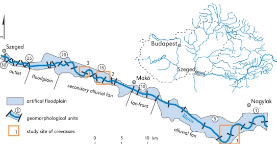
The Hungarian section of the Maros flood- plain was studied in detail, between Nagylak and Szeged (53.7 km). The Maros constitutes the border between Romania and Hungary along the upstream section (units 1-12), then it flows entirely in Hungary until its conflu- ence with the Tisza River. Therefore, the LiDAR survey covers just the northern part of the floodplain along the upstream border section, whilst at downstream (units 13-31) both floodplain sides were analysed (Fig. 1.).
The upstream floodplain section (units 1-8) is located on the alluvial fan of the river with high slope (0.00038), the next sections are the fan-front (units 9-11), and the second- ary alluvial fan (units 12-20), therefore here the floodplain slope decreases to 0.00012- 0.00022. After leaving the alluvial fan the river flows across its natural floodplain (units 21-24) with a slope of 0.00005, whilst on the most downstream section (units 25-31) it drops to 0.00002 (Kiss et al., 2011).
The discharge of the Maros at the Makó gauging station varies between 21-2450 m3 s-1 (Sipos, Kiss, & Fiala, 2007). In the 19-20th centuries the floods lasted for 6-21 days y-1, however, in recent decades floods were miss- ing or lasted just for 1-1.5 days (Kiss, 2014).
The Tisza River also influences the duration of floods on the Maros, as the Tisza impounds the floods from the confluence up ca.
28 km (to Makó). The Maros has a consider- able sediment discharge: the average amount of suspended load is 265 kg s-1 (8.3 mil- lion t y-1), and of the bed-load is 0.9 kg s-1 (28,000 t y-1; Bogárdi, 1971).
On the Maros river regulation works start- ed in the 1850s (Ihrig, 1973). Continuous arti- ficial levee system was built in the study area (Nagylak−Szeged), but along the upstream reach, the levee system is not continuous, as the villages were established on terraces.
The levee system was built along the 19th c. meanders (the channel was straightened later; Ihrig 1973), thus the width of the flood- plain varies (0.5-3.5 km). The river was short- ened (from 260 km to 172 km) by artificial cut-offs between Lipova and Szeged (1846- 1871), thus the mean channel slope doubled (Laczay, 1975). The increased slope resulted
in accelerated bank erosion and channel inci- sion (ca. 1.0 m), thus the amount of transport- ed sediment greatly increased (Kiss, 2014), causing accelerated island and bar forma- tion, which led to the development of island- braided channel pattern in the upstream sec- tion (Sipos, 2006). The overbank aggradation was the most intensive (1.2-2.5 cm y-1) at the time of channel and floodplain regulations as a consequence of increased sediment transport (especially after cut-offs), narrowed floodplain and more frequent floods (Kiss et al., 2011). In the 19-20th centuries the flood- plain aggradation rate was outstanding com- pared to other rivers of the Carpathian Basin (Kiss et al., 2011), however, nowadays the role of floods is minor in the formation of flood- plains, due to the decreased length of floods in connection with water retention and chan- nel incision (Kiss et al., 2017). The lower sec- tion downstream of Makó was designed to have a sinuous pattern, and later, in the 20th c. this section was fixed by groynes and revetments. Since the 1950s the width of the channel decreases (Sipos, 2006) in connection with revetment constructions, water reten- tion, water withdrawal (which caused flood duration decrease), and in-channel gravel
Budapest
Szeged
Maros Szeged
Makó
Nagylak
study site of crevasses
1 2
3
1
$
10 30outlet
floodplain
fan-front
alluvial fan
1
20
15
25 20
secondar
y alluvial fan
Mar 5
os artifical floodplain
geomorphological units 1
0 5 10 km
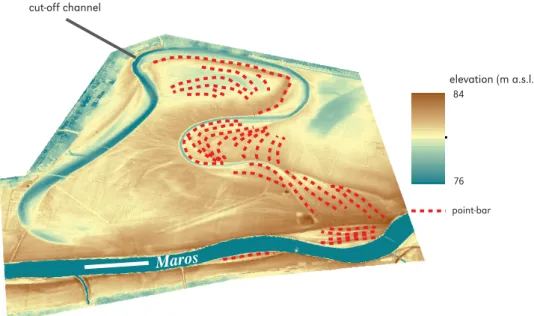
Figure 1. The research was carried out on the floodplain of the Maros River between Nagylak and Szeged. The area was dissected into geomorphological units (1-31). Crevasses were identified and analysed at 3 study sites
mining (Kiss et al., 2017). The narrowing was the most intensive (12-15 m y-1) in the 1950- 1960s, then its rate decreased (Blanka, Sipos,
& Kiss, 2006). The narrowing of the upper (island-braided and meandering) section was greater by 40% that of the lower sinuous sec- tion (Sipos, 2006). The process created new low-lying floodplain sections along the entire studied reach of the Maros (Kiss et al., 2017).
Methods
To study the width conditions of the chan- nel and to identify narrowing sections, the banklines were digitised on the Third Mili- tary Survey (made in 1881, after the channel regulations) and on the LiDAR image (2014).
The channel width was measured at every 100 m perpendicular to the centre-line
of the river. A digital elevation model based on LiDAR survey (vertical accuracy
±0.1 m measured by RTK-dGPS; the DEM was provided by the Lower Tisza District Water Directorate) was applied to identify and measure the morphometric parameters of natural levees, crevasses, and point-bars.
The studied floodplain area is bordered by constructed (artificial) levees and the state border between Romania and Hungary (Fig. 1). The measurements were done using ArcGIS 10.2 software.
The studied reach of the Maros was divided into 31 units (single meanders, bends or straight ones), which were separated by inflexion points. On the digital elevation
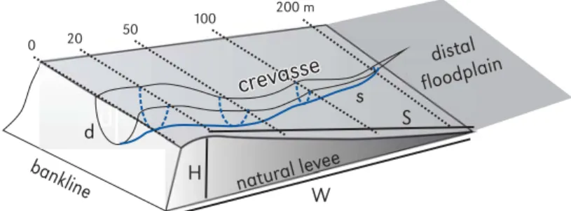
model, the natural levees appeared as almost continuous forms along the slightly sinuous bends, whilst along meandering sections they were intercalated by point-bars. Therefore, the length of these forms could not be meas- ured precisely, thus, it was not quantified. The width and height of natural levees and point- bars were defined in a similar way, drawing cross-sections perpendicular to the centre- line of the river, across the highest point of the forms. In each unit, the measurements were made along with these profiles. The width of the forms was determined by the bankline on one side, while on the other by the break- ing point of the slope (Fig. 2). Their relative height was measured from the bankline. The surface slope (m m-1) of the forms was calcu- lated as the ratio of the relative height and width.
Crevasses appeared only at three units, where they were identified by using the Flow Direction tool in ArcGIS 10.2. Their depth was measured at 20, 50, 100, 250 and 500 m from the bankline (Fig. 2). The density of the crevasses (km km2 -1) and their seg- mentation (junction km2 -1) were also deter- mined. The slope (m m-1) of the crevasses was calculated from their length and the height difference between their two ends.
Results
The channel of the Maros became consid- erably narrower in the last 130 years, as in 1881 the average width was 155 m (max:
d S
natural levee
H W
0 20 50 100 200 m
s
d S
crevasse
bankline
distal floodplain
crevasse
Figure 2. Morphometric parameters of natural levees (H: height, W: width, S: slope) and crevasses (d: depth, s: slope)
490 m; min: 60 m) while in 2014 it reduced to 115 m (max: 176 m; min: 72 m). Thus, the average rate of narrowing was 0.3 m y-1, and it affected 88% of the studied reach.
The greatest width reduction was found for unit 13, where the maximum channel width was reduced by 77% (1881: 490 m; 2014:
113 m). The most intensive narrowing char- acterised the meandering and braided sec- tion (units 1-21), while the channel width of the slightly sinuous downstream section (units 22-31) remained the same, or at the apex of some bends, it even increased.
The process of intensive channel narrow- ing enabled the development of point-bars and created new floodplain surfaces suit- able for natural levee accumulation, though at a lower elevation.
Natural levees
In the study area, 32 active and 20 inactive natural levees were identified. In 16 units only active natural levees were identified, however in 15 units both active and inactive natural levees appeared, thus in some places dou- ble or triple natural levee systems developed as the bankline was removed from the forms due to channel narrowing.
The widest (1022 m) natural levee is locat- ed along a meander on the upstream section (unit 1), where the floodplain is wide (3400 m) and the rate of lateral channel shift is low (0.3 m y-1). The height of this particular natu- ral levee (1.7 m) is just about average (1.7 m), thus its slope is very low (0.0005). The high- est (3.1 m) natural levee developed along a straight section (unit 15) and it is relatively narrow (71 m), therefore it has a greater slope (0.0436). In general, the narrowest natural levees have the greatest slopes (slopemean: 0.0428), while the wider forms have gen- tle slopes (slopemean: 0.0052), thus a nega- tive correlation was found between these parameters.
The narrowest active natural levee (width:
18 m; height: 1.8 m) developed on the new floodplain surface created by channel nar- rowing (unit 9). Here, a double natural levee
developed, as along the inactive bankline the formation of the older natural levee terminat- ed, and by the actual bankline a new, active form is evolving.
The size of the natural levees is influenced by the sinuosity of the channel. Usually, the natural levees along sharp meanders (sinu- osity over 1.4) are 1.7-2.5 times wider, but no clear correlation exists between the height of the forms and channel sinuosity. However, the steepest natural levees are located along slightly sinuous sections.
As the locations of 19th c. artificial cut- offs and 20th c. channel narrowing are known, it is possible to evaluate their role in natural levee development. No cut-offs were made on the upstream section (units 1-6), thus here the natural levees are along three large meanders and they develop con- tinuously (at least) from the 19th c. These old, and still active natural levees are wide (widthmax: 1022 m), and they have low slopes (slopemax: 0.0076). On the downstream part of the study area (units 7-31), several mean- der cut-offs were made, so those natural levees which belonged to them became inactive, and new forms started to develop along the new artificial channel. Thus, these young natural levees have been evolving just for ca. 150 years, therefore they are nar- rower (widthmax: 768 m), though they mean height is almost at the average of all levees (heightmean 1.7 m), as a consequence, they have steeper slopes (slopemax. 0.0420), than of the natural levees along the upstream section. The youngest natural levees evolved on the new, low-lying floodplain sections cre- ated by channel narrowing, resulting in the inactivity of the previous natural levees (Fig. 3). Altogether, they appear in 12 chan- nel units. These young levees are narrow (widthmax: 79 m), but they are the highest (heightmax: 3.1 m) forms, thus they have the steepest slopes (slopemax: 0.0991). As nar- rowing is a quite new process, behind these new natural levees additional older and nowadays inactive natural levees could be identified.
Crevasses
Crevasse systems developed just along such sections where no meander cut-off was made and the channel remained almost in the same position due to low (≤0.3 m y-1) lateral erosion (units 3-4, unit 15, and units 18-19;
Fig. 4). The lateral shift of the channel along these sections is inhibited by cohesive bank material (No. 1. study site) or revetments (No. 2-3 study sites). Identifiable crevasses did not appear along other sections.
The uppermost crevasse system devel- oped along with a meander (No. 1 study site;
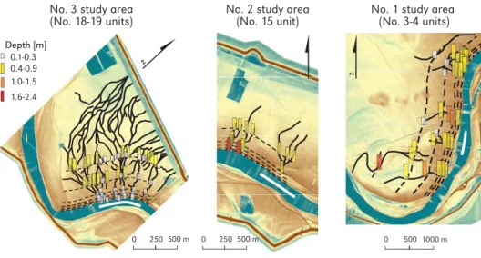
Fig. 4), where the slope of the Maros is great (0.00038). The mean depth of these crevass- es is 0.7 m (depthmax: 0.8 m) at 20 m far from the bankline, and towards the distal parts (50-500 m from the bankline) it decreases to 0.4 m in average. The deepest crevasse (depthmax: 0.8 m) developed at the apex of the meander. In this study area, the crevasses are generally short (400-600 m) and they termi- nate at the rim of the natural levees, because here the cultivation (ploughing) already lev- elled all fluvial forms. In the study area, the total length of the crevasses is 6.6 km, thus their mean density is 2.2 km km2 -1, and they
are not segmented (1.0 junction km2 -1), prob- ably because they stretch just to the edge of the natural levees. The mean slope of the crevasses is 0.00015. The longest (lengthmax: 1.6 km) and the steepest (slopemax: 0.00030) crevasse developed behind a point-bar in the southern part of the study area (indicated by red column on Fig 4, Study site 1), thus dur- ing floods it could act as a chute channel.
On the lower section of the Maros crevass- es developed along a slightly bending section (No. 2 study site) with 0.00012 mean water slope; and along a meander (No. 3 study site) with 0.00005 slope. In No. 2. study site the crevasses are easily identifiable (Fig. 4), as their mean depth is 1.5 m (varies between 1.0-1.8 m) at 20 m far from the bankline. Far- ther from the bankline, at 50 m distance, their depth reduces to 0.7-0.9 m, and their distal sections become even shallower (at 250 m:
0.6 m; at 500 m: 0.4 m). The density of the crevasse system is 2.7 km km2 -1, they have more junctions (4.0 junctions km2 -1), and their mean slope is 0.00017, thus all parameters are greater than in the No. 1. study site. Here the steepest crevasse (slopemax: 0.00041) also developed at the apex of the bend.
Maros
former wide channel
new floodplain surface
natural levee
elevation (m a.s.l.) 86
79
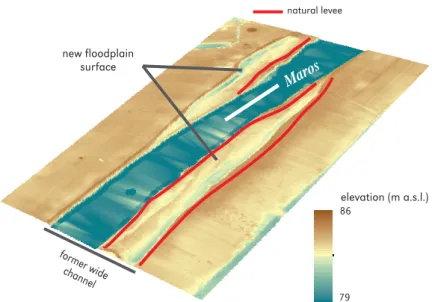
Figure 3. Natural levees could develop behind each other. In the given case younger natural levees developed on low-lying floodplain surfaces created by channel narrowing
The No.3 study site is also located on the downstream section of the Maros, but in contrast to the previous site, it is located at a meander (Fig. 4). Here the crevasse system is the most complex, as its density (8.4 km km2 -1) is 3-4 times higher than of the upstream areas. The crevasses terminate in artificial clay pits in front of the construct- ed levees. The crevasses are quite shallow (0.1-0.3 m) near the bank (at 20 m), but they are getting deeper towards the distal part of the floodplain (50-500 m zones), as their mean depth increases to 0.4 m (depthmax: 1.0 m). The crevasses create a complex sys- tem, as it is reflected by their high segmenta- tion (21 junctions km2 -1). However, the mean slope of the crevasses (0.00015) is similar to the other study areas, but considerably higher than the mean water slope of the main channel. The steepest crevasse (slopemax: 0.00032) is located at the apex of the mean- der, where the thalweg is probably situated closest to the bank.
Point-bar systems
Point-bars were identified at 26 bends, but only 18 point-bars are actively forming, while
at 9 meanders the point-bar systems became inactive as the result of 19th c. artificial cut- offs.
The inactive point-bar systems are dif- ferent on the upper and lower units. In the upper units (units 9-11) the point-bar systems are wide (524-1133 m) containing 11-34 ridg- es. The width of the individual point-bars is 63-79 m. In contrary, in the lower units (units 17-24) the point-bar systems have only 5-22 ridges, and they are narrower (172- 921 m), but the width (50-115 m) of individ- ual point-bars is higher (Fig. 5). Though the maximum height of the point-bars (0.3-1.0 m) does not reflect a downstream trend, but within the point-bar systems the ridges have characteristic height changes. In the upper units the highest point-bars are located in the youngest third of the point-bar system, whilst in the downstream units, the highest ridges are always located right on the banks of the cut-off meanders.
The active point-bar systems are less developed, as in the upper units (units 1-4) they have only 6-11 members and their width changes between 265 and 926 m.
Their height is 0.9-1.4 m (heightmean: 1.2 m), and it decreases downstream. In contrast,
0.1-0.3 0.4-0.9 1.0-1.5 1.6-2.4 Depth [m]
No. 1 study area (No. 3-4 units) No. 2 study area
(No. 15 unit) No. 3 study area
(No. 18-19 units)
0 500 1000 m 0 250 500 m
0 250 500 m
$
$ $
Figure 4. Crevasse systems were identified at three sites. The depth conditions of the crevasses were measured at given distances (0-20-50-100-200-500 m) from the bankline
in the downstream units (units 13-31) the number of point-bars is more variable (4-13), but the width of the point-bar system is only 96-709 m, and they are slightly lower (0.4-1.5 m; mean. 0.8 m).
Discussion
General morphology of natural levees and point-bars
On the floodplain of the 53.7-km long reach of the Maros River the LiDAR-based DEM enabled us to identify 0.3-3.1 m high natu- ral levees, 0.3-2.0 m deep crevasses break- ing through the natural levees and 0.4- 1.5 m high point-bars which form point-bar systems. Whilst natural levees and point-bars were identifiable along the whole reach of the Maros, crevasses appeared just in three areas.
The natural general trend in the dimen- sions of the forms is surpassed by direct and indirect human impacts: the channel develop- ment is modified by cut-offs and narrowing, the floodplain evolution is restricted by con- structed levees which are located to various
distances from the channel, and finally the surface of the floodplain is modified by pla- nation (ploughing) and excavation (clay-pits).
The horizontal growth of natural levees could be limited by constructed levees, clay-pits and other artificial forms (e.g. small dikes, elevated roads, canals).
Along the upper part of the studied reach of the Maros (units 1-12) the lateral growth of the natural levees is not limited by con- structed levees, as here the floodplain is wide (3.4 km). Besides, here the meanders devel- op for centuries (at least they have existed in their present form since the first surveys of the 18th c.), thus hundreds of floods could accumulate the material of the natural levees, widening them and creating gentle slopes, but at the same time the low rate of lateral channel shift (0.3 m y-1) did not destroy them.
These factors created favourable conditions for a long and undisturbed evolution for both the natural levees and their crevasse sys- tems. On the opposite bank, active point-bars and point-bar systems developed. These are the highest and widest point-bars of the study area, as the slow lateral channel migration Maros
cut-off channel
point-bar elevation (m a.s.l.)
84
76
Figure 5. Point-bar systems became inactive along an artificially cut-off channel, but new, active ones developed along the new channel
did not allow point-bar development over extensive areas, thus their rather increased in height and width; and instead of the devel- opment of point-bar system with a high num- ber of members, only some point-bars build them up.
In contrast, along the downstream section (units 13-31) the evolution of the natural lev- ees is controlled by the quite narrow (1.6 km) floodplain, the fast lateral migration of the channel (1.2 my-1), and river engineering works. Here the bends are very close to the constructed levees, therefore, the lateral expansion of the natural levees is limited and their vertical growth could result in the gen- eral aggradation of the floodplain. Here the 19-20th c. clay-pits in front of the construct- ed levees also influence the development of the natural levees, as primarily the mate- rial is deposited here, and the natural levee as a positive form could appear on the digital elevation map only after the clay-pit is filled up. Along this section the development of the point-bars matches to the fast channel migra- tion too, thus they have more numerous, narrower and slightly lower ridges.
General morphology of crevasses Crevasse systems are limited to only three sections, where the channel is at the same location for centuries and the old natural levees are active. The depth of the crevass- es varies with the three study areas: in the upper two sites the crevasses are incised to the half of the height of the natural lev- ees, whilst on the most downstream site they are incised just to 20-25% of the natural lev- ees. The densest and shallowest crevasse system developed on the lowermost section with the lowest slope of the Maros. It could be explained by the length of floods, as at the given section the impoundment of floods is typical: when the floods of the Tisza and Maros coexist, the flood of the Maros is blocked by the backwater effect. There- fore, in the lower section floods are longer and slower, thus, more time is available for the development of a dense crevasse system,
however, the stream power is not enough for their deep incision.
The slope of the crevasses is higher by an order than the slope of the Maros; but while the slope of the river decreases downstream, the slopes of the crevasses remain similar.
The deepest and steepest crevasses devel- oped at the apex of bends and meanders, where the thalweg is closest to the bankline, thus the flow in the crevasse could be the most powerful. In the lowermost study area, at their entrance crevasses are very shallow.
Just in comparison: 20 m far from the bankline in uppermost No. 1 study area the mean cre- vasse depth is 0.6 m, in No. 2 study area it is 1.5 m, and at the lowermost No.3 study area the crevasses are only 0.2 m deep on aver- age. At the same time, the depths at the distal parts of the crevasses are the same:
at 250 m they are uniformly 0.4-0.5 m deep.
Thus, at the lowermost study area probably a sediment plug developed in the crevasses during an impounded flood.
The development and preservation of the forms are highly influenced by direct and indirect human impact. The crevasses could drain water into the deep clay-pits in front of the natural levees, thus artificial hollows could support their water-draining function, and serve as sediment sinks. Therefore, the artificial excavational forms could sustain their development and long existence. In con- trast, the ploughing of agricultural fields could destroy the shallow crevasses, especial- ly in the distal part of the floodplain. On the other hand, water retention related flood fre- quency decrease contributes to their aggra- dation, as sediment plugs developed at their proximal parts.
Human impact on natural levee and point-bar development
Human impact is a very important controlling factor on the evolution of natural levees and point-bar systems, as in both cases active and inactive forms were identified. Active natu- ral levees and point-bars develop along the actual bank-line, whereas their terminated
development is clearly related to bank-line changes, which is explained by artificial cut- offs and channel narrowing caused by indi- rect human impacts. In this way, not only series of point-bars developed, but also dou- ble or even triple natural levees, which is quite unlikely on natural, equilibrium floodplains.
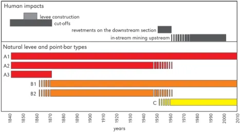
Altogether, six natural levee and point-bar generation types are distinguishable along the Maros River (Fig. 6):
A) well-developed natural levee and point-bar system at the time of the 19th c. river regu- lations with
A1) continuous development ever since;
A2) terminated development due to chan- nel narrowing since the 1950s;
A3) terminated development due to an artificial cut-off in the 19th c.;
B) natural levee and point-bar system develop- ment started during the 19th c. river regula- tions, when a cut-off was made and a new channel was created, and the form has B1) continuous development since that
time;
B2) terminated development due to chan- nel narrowing since the 1950s;
C) the youngest, actively forming natural levee and point-bar started to develop when the channel became narrower (since the 1950s) and on the new floodplain section the evo- lution of the natural levee could start.
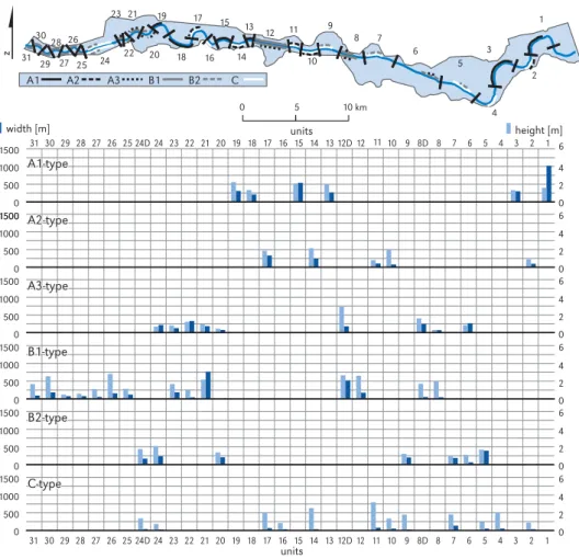
Natural levees belonging to the A1 type develop for centuries, thus, they are the wid- est (widthmean: 441 m, widthmax: 1022 m) forms in the study area, their mean height (height-
mean: 1.8 m) is the greatest of all types (Fig. 7, Tab. 1), thus these natural levees have the smallest slope too (slopemean: 0.0016-0.0076).
The crevasses developed just across this type of natural levee. As the evolution of A2-type natural levees was long, but it terminated by channel narrowing in the mid-20th c., they are narrower (widthmean: 173 m, widthmax: 333 m), and slightly lower (heightmean: 1.4 m) forms than those belong to A1 type. The larg- est number of old natural levees belongs to the A3 type. Their width is similar to A2, but their average height (heightmean: 1.1 m) is the lowest in class A, as due to the cut-offs they got far from the active channel during the last ca. 150 years. The spatial distribution of these types is determined by the spatiality of the 19th c. regulation works. The A1 and A2 type levees survived where the meanders of the Maros were not very sharp, thus they were not cut off. Such, unmanaged units are located in the upstream (1-3 units) and in the middle section (10-19 units). As the evolution of the A3 type terminated by cut-offs, they are mostly located where the channel was straightened, thus they are found behind the members of class B.
Human impacts
A1 A2 A3
B1 B2
C
1900 1910 1920 1930 1940 1950 1960 1970 1980 1990 2000 2010
1840 1850 1860 1870 1880 1890
revetments on the downstream section Natural levee and point-bar types
levee construction
years cut-offs
in-stream mining upstream
Figure 6. Development types of natural levees and point-bars related to various human impacts
B-type natural levees have been develop- ing since the 19th c. cut-offs, on the newly created, usually straight or slightly sinuous
channel sections. Their width (widthmean: 182- 208 m) and height (heightmean: 1.5-1.7 m) are almost the same, or higher, than of the A2 and Table 1. Main characteristics of the identified natural levee types (n: number of studied forms)
Type n Width [m] Height [m] Slope [m m-1]
min mean max min mean max min mean max
A1 6 210 441 1022 1.3 1.8 2.2 0.0016 0.0052 0.0076
A2 4 78 173 333 0.8 1.4 1.9 0.0056 0.0074 0.0092
A3 9 69 187 329 0.3 1.1 2.9 0.0031 0.0061 0.0165
B1 14 42 182 768 0.4 1.7 2.8 0.0051 0.0159 0.0420
B2 7 63 208 391 1.0 1.5 2.1 0.0043 0.0084 0.0174
C 12 18 46 79 0.7 1.6 3.1 0.0220 0.0428 0.0991
1
2 3
4 5 6 7 8 9
10 13 12
14 15
16 17
18 19
20 21
22 23
25 24 26 27 28 29 30 31
11
1500 1000 500
0 0
2 4 6
1000 500
0 0
2 4 1500 6
1500
0 2 4 6 1000
500 0 1500
1000 500
0 0
2 4 6 1500
1000 500
0 0
2 4 1500 6
1000 500
0 0
2 4 6 1500
A1-type
31 30 29 28 27 26 25 24D 24 23 22 21 20 19 18 17 16 15 14 13 12D 12 10 9 8D 8 7 6 5 4 3 2 1 31 30 29 28 27 26 25 24D 24 23 22 21 20 19 18 17 16 15 14 13 12D 12 10 9 8D 8 7 6 5 4 3 2 1
width [m] units height [m]
units A2-type
A3-type
B1-type
B2-type
11 11
$
A1 A2 A3 B1 B2 C
0 5 10 km
A1-type
A2-type
A3-type
B1-type
B2-type
C-type A1-type
A2-type
A3-type
B1-type
B2-type
C-type
Figure 7. Type and morphometric parameters (width and height) of the identified natural levees at a given unit
A3 types (Tab. 1), whilst their slope (slopemean: 0.0084-0.0159) is greater. Probably, this could be explained by the disturbance itself, as at the time of the regulations the amount of sediment transport increased exceptionally (Kiss, 2014), as only a narrow pilot-channel was dug, and the river had to erode the new channel for itself, producing extra sediment load. Thus, an increased amount of sedi- ment was available for the rapid evolution of new natural levees. As the development of B2 type levees stopped due to channel nar- rowing, their parameters are slightly lower than of the continuously developing B1. The channel of the Maros was straightened in the upper section (units 5-12), and downstream of the 20th unit, the B1 and B2 type natural levees appear along with these units.
The members of class C are the young- est, as they evolved on the new, low-lying floodplain surfaces formed by channel nar- rowing (Kiss et al., 2017, 2018). Though these forms are the narrowest (widthmean: 46 m), they are high (heightmean: 1.6 m), therefore they have the steepest slopes (slopemean: 0.0428; Tab. 1). As they all developed on the low-lying surfaces, their aggradation is very intensive, primarily because small but more frequent flood-waves could accumulate sedi- ment here, secondary because these (near- bankfull) floods transport the highest amount of sediment. In contrary, on the higher flood- plain sections, the older natural levees could evolve just during exceptionally large floods (Kiss et al., 2018). C-type natural levees are almost evenly distributed along the studied reach of the Maros, as almost the whole reach is intensively narrowing, though near to the confluence (units 25-31) the members of the C-type are missing, as here the channel slightly widened.
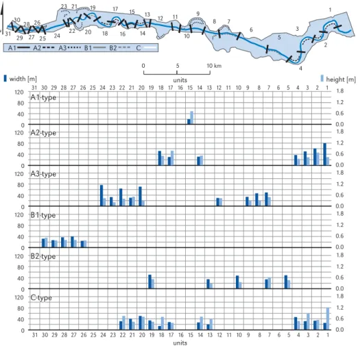
The point-bar systems could be grouped to the same classes as the natural levees, as they developed on the other side of the channel under similar direct or indirect human impacts. A-type point-bar systems have the longest development. A single A1 type point- bar system survived (unit 15) containing only 7 ridges, which follow the slight incision of the
channel, thus their height decreases towards the channel (Fig. 8, Tab. 2). The A2 type point- bar systems developed for a long time, but their evolution was stopped by the narrow- ing of the channel, and they have no active point-bar surface. Their mean height is simi- lar to the A1, but the highest point-bar is usu- ally located at the channel, thus only high floods could built them, thus their morphol- ogy changes towards of a natural levee. The development of the A3 type point-bar sys- tems was terminated by the 19th century artificial cut-offs. They contain the largest number of point-bars (4-17) referring to rapid meander migration before the channel regu- lations (therefore these meanders had to be straightened). Their mean height is similar to A1, but – similarly to A2 – the highest ones are located by the cut-off channel. It could be explained by way of channel regulations:
the cut off was made applying narrow pilot channels, thus in the cut-off section water flow decreased gradually during one or two decades. As the sediment load and the flood levels of the Maros increased during the regu- lation works, they resulted in very intensive point-bar formation during the slow decline of the cut-off channels.
The B-type point-bars develop since the 19th c. channel regulation along the arti- ficially created sinuous channel sections.
They are higher than of the members of the A-class, but height conditions of the point-bar members show no clear tendency towards the channel. Usually, they are getting nar- rower towards the active channel, referring to less active formation since the channel regulations.
The C-type of point-bar systems is the youngest, as they develop on the new, low- lying floodplain surfaces created by chan- nel narrowing. Though they are young, they already contain 3-7 ridges, but these are the highest and narrowest ones of all point-bar systems, similarly to the C-type of natural levees. The development of the C-type point- bars the most closely related to channel dynamics: at intensively narrowing channel sections they develop very rapidly, thus their
1
2 3
4 5 6 7 8 9
10 13 12
14 15
16 17
18 19
20 21
22 23
25 24 26 27 28 29 30 31
120 80 40
0 0.0
0.6 1.2 1.8
120 80 40
0 0.0
0.6 1.2 1.8
120 80 40
0 0.0
0.6 1.2 1.8
120 80 40
0 0.0
0.6 1.2 1.8
120 80 40
0 0.0
0.6 1.2 1.8
120 80 40
0 0.0
0.6 1.2 1.8
A1-type
units A2-type
A3-type
B1-type
B2-type
units
A1 A2 A3 B1 B2 C
11
width [m] height [m]
$
0 5 10 km
31 30 29 28 27 26 25 24 23 22 21 20 19 18 17 16 15 14 13 1211 10 9 8 7 6 5 4 3 2 1
31 30 29 28 27 26 25 24 23 22 21 20 19 18 17 16 15 14 13 1211 10 9 8 7 6 5 4 3 2 1
A1-type
A2-type
A3-type
B1-type
B2-type
C-type A1-type
A2-type
A3-type
B1-type
B2-type
C-type
Figure 8. Type and mean morphometric parameters (width and height) of the identified point-bars at a given unit
Table 2. Main characteristics of the identified point-bar systems
Type
Point-bar systems Single point-bar within point-bar systems
height width
members mean width [m] min.
[m] mean
[m] max.
[m] min.
[m] mean
[m] max.
[m]
A1 7 165 0.2 0.4 0.9 12 24 58
A2 6-10 477 0.2 0.5 1.4 8 58 139
A3 5-34 579 0.1 0.4 1.0 6 49 115
B1 5-7 159 0.2 0.5 1.5 6 29 63
B2 4-13 268 0.2 0.5 1.6 8 141 132
C 3-7 121 0.3 0.6 1.7 8 30 60
height is decreasing towards the channel, while along less intensively narrowing sec- tions their height is increasing, due to the limited lateral aggradation.
Conclusions
The detailed LiDAR-based DEM enabled us to identify the fluvial forms of the flood- plain and to analyse their morphology. Ear- lier studies had already emphasized the role of human impact on various rivers (Gregory, 2004; Steiger et al., 2005), however they usu- ally focused on their hydrological or channel pattern changes (Łajczak, Plit, Soja, Starkel,
& Warowna, 2006, Sipos et al., 2007), but in lack of detailed elevation data on flood- plain forms it was impossible to evaluate the human impact on floodplain form assem- blage. However, Falkowski (1990) theoreti- cally proved, that various development state of the river channel (e.g. young or mature) resulted in different floodplain forms and sedimentary environments, thus we could also suppose that creating artificial chan- nel sections and cutting off meanders could influence floodplain forms.
The 18 artificial cut-offs shortened the studied length of the Maros by 38%, while channel narrowing affected 88% of the reach.
The narrowing is connected to (1) the incision of the base level (Tisza River) caused by chan- nel regulation (Kiss, 2014), (2) in-stream gravel mining (Urdea, Sipos, Kiss, & Onaca, 2012), (3) dam and reservoir constructions, and (4) the resulted decreasing frequency and magnitude of floods (Kiss, 2014). Both human impacts resulted in the disconnection of the older nat- ural levees, crevasses, and point-bars from the channel, thus their classical development terminated, though during large floods sus- pended sediment could be deposited on their surface. On the contrary, along the artificially created channel sections, and on the newly developed low-lying floodplain surfaces new natural levees and point-bar systems develop. Their rapid evolution is reflected by their considerable height, as during the dis- turbance (digging new pilot channels) the
sediment transport of the Maros increased considerably (Kiss et al., 2014), supporting the rapid evolution of the studied near bank forms. However, crevasses were not identi- fied in these areas, thus the form assemblage impoverished due to human impact.
Based on the spatial and temporal char- acteristics of the natural levees and point- bar systems six generation types were dis- tinguished, considering the beginning (i.e.
pre-19th c., 19th c., and 20th c.) and the end of their development (19thc., 20th c., or still active). These differences are undoubtedly connected to human impact on the river.
The studied natural levees, crevasses and point-bar systems could be considered as cou- pling forms between the channel and the flood- plain, as the development of these floodplain forms is primarily controlled by water and sed- iment transport. From this point of view, the studied forms on the Maros floodplain reflect weakening connection between the channel and the floodplain, as their development is not continuous and undisturbed, nor in space neither in time. Even the development of the newly born (19-20th c.) natural levees and point-bars could terminate, if the channel nar- rowing continues in the future, thus gradually the floodplain will be decoupled.
Comparing the size of the floodplain forms of the Maros with other river’s (see Bown &
Kraus, 1987; Brierley et al., 1997; Cazana- cli & Smith, 1998), it seems that the dimen- sions of the natural levees are quite different, depending on the water and sediment dis- charge of the rivers, the width of the flood- plain and the human impacts.
Acknowledgement
The research was supported by the Hungar- ian Research Foundation (OTKA 119193).
Thanks for Prof. G. Mezősi for his useful advic- es and support.
Editors‘ note:
Unless otherwise stated, the sources of tables and figures are the authors‘, on the basis of their own research.
References
Allen, J.R.L. (1965). A review of the origin and characteristics of recent alluvial sediments. Sedimentology, 5, 89-191. https://doi.org/10.1111/j.1365-3091.1965.tb01561.x
Asselman, N.E.M., Middelkoop, H. (1998). Temporal variability of contemporary floodplain sedimentation in the Rhine-Meuse Delta, the Netherlands. Earth Surface Processes and Landforms, 23, 595-609.
https://doi.org/10.1002/(sici)1096-9837(199807)23:7<595::aid-esp869>3.0.co;2-y
Blanka, V., Kiss, T. (2006). Case study on meander development of the downstream section of River Maros. Hidrológiai Közlöny 86(4), 19-22. [in Hungarian]
Blanka, V., Sipos, Gy., Kiss, T. (2006). Spatial and temporal changes of meander formation on the Hun- garian section of the River Maros. In Kertész, Á., Dövényi, Z., Kocsis, K., (Eds.), III. Magyar Földrajzi Konferencia (pp. 1-10), Budapest: MTA-FKI. [in Hungarian]
Bogárdi, J. (1971). Sediment transport of rivers. Budapest, Hungary: Akadémiai Kiadó. [In Hungarian].
Bown, T.M., Kraus, M.J. (1987). Integration of channel and floodplain suites, I. Developmental sequence and lateral relations of alluvial paleosols. Journal of Sedimentary Petrology, 57, 587-601.
https://doi.org/10.1306/212f8bb1-2b24-11d7-8648000102c1865d
Branß, T., Dittrich, A., Núñez-González, F. (2016). River flow. In Constantinescu G., Garcia M., Hanes D.
(Eds.), Reproducing natural levee formation in an experimental flume (pp. 1122-1128.), London: Taylor &
Francis Group.
Bridge, J.S. (2003). Rivers and floodplain: Form, processes, and sedimentary record. Oxford: Blackwell,.
Brierley, G.J., Ferguson, R.J., Woolfe, K.J. (1997). What is a fluvial levee? Sedimentary Geology, 114(1-4), 1-9. https://doi.org/10.1016/S0037-0738(97)00114-0
Brierley, G.J., Hickin, E.J. (1992). Floodplain development based on selective preservation of sediments, Squamish River, British Columbia. Geomorphology 4, 381-391.
https://doi.org/10.1016/0169-555X(92)90033-K
Brown, A.G. (1983). An analysis of overbank deposits of a flood at Blandford-Forum, Dorset, England.
Revue Geomorphologie Dynamique, 32(3), 95-99.
Cazanacli, D., Smith, N.D. (1998). A study of morphology and texture of natural levees, Cumberland Marshes, Saskatchewan, Canada. Geomorphology, 25, 43-55.
https://doi.org/10.1016/S0169-555X(98)00032-4
Chalov, R.S. (2004). Morphological expressions of river sediment transport and their role in channel processes. IAHS Publication, 288, 205-211.
Coleman, J.M. (1969). Brahmaputra River: Channel processes and sedimentation. Sedimentary Geology, 3, 129-239.
Dietrich, W.E., Wilson, C.J., Reneau, S.L. (1986). Hollows, colluvium, and landslides in soil-mantled land- scapes. In Abrahams, A.D. (Ed.), Hillslope processes (pp. 361-388). Boston: Allen and Unwin.
Falkowski, E. (1990). Morphogenetic classification of river valleys developing in formerly glaciated areas for the needs of mathematical and physical modelling in hydrotechnical projects. Geographia Polonica, 77(2), 55-68.
Fisk, H.N. (1947). Fine-grained alluvial deposits and their effects on Mississippi River activity. Vicksburg, Miss.: Waterways Experiment Station, Mississippi River Commission.
Fryirs, K.A., Brierley, G.J. (2012). Geomorphic analysis of river systems: An approach to reading the landscape.
In K. Fryirs, G. J., Brierley, Geomorphic analysis of river systems (pp. 1-8). Chichester: Wiley-Blackwell.
Gábris, Gy., Telbisz, T., Nagy, B., Belardinelli, E. (2002). Accumulation of the floodplain of the Tisza and its geomorphological background. Vízügyi Közlemények, 84, 305-318. [in Hungarian]
Gomez, B., Phillips, D., Magilligan, F.J., James, L.A. (1997). Floodplain sedimentation and sensitivity:
Summer 1993 flood, Upper Mississippi Valley. Earth Surface Processes and Landforms, 22, 923-936.
https://doi.org/10.1002/(sici)1096-9837(199710)22:10<923::aid-esp763>3.0.co;2-e
Gregory, K.J. (2004). Human activity transforming and designing river landscapes: A review perspective.
Geographia Polonica, 77(2), 5-20.
Happ, S., Rittenhouse, G., Dobson, G. (1940). Some principles of accelerated stream and valley sedimen- tation. Technical Bulletin, 695, US Department of Agriculture.
Hudson, P.F., Heitmuller, F.T. (2003). Local and watershed-scale controls on the spatial variability of natu- ral levee deposits in a large fine-grained floodplain: lower Pánuco Basin, Mexico. Geomorphology, 56, 255-269. https://doi.org/10.1016/s0169-555x(03)00155-7
Ihrig, D. (1973). History of the river regulations in Hungary. Budapest: Orszá gos Ví zü gyi Hivatal. [in Hungarian]
Keen-Zebert, A., Tooth, S., Rodnight, H., Duller, G.A.T., Roberts, H.M., Grenfell, M. (2013). Late Quater- nary floodplain reworking and the preservation of alluvial sedimentary archives in unconfined and confined valleys in the eastern interior of South Africa. Geomorphology, 185, 54-66.
https://doi.org/10.1016/j.geomorph.2012.12.004
Kiss, T. (2014). Alterations of fluvial processes due to anthropogenic impacts: Study on Equilibrium and sensitivity in fluvial environment. University of Szeged, Hungary. (Doctoral dissertation, in Hungarian) Kiss, T., Balogh, M., Fiala, K., Sipos, Gy. (2018). Morphology of fluvial levee series along a river under
human influence, Maros River, Hungary. Geomorphology, 303, 309-321.
https://doi.org/10.1016/j.geomorph.2017.12.014
Kiss, T., Blanka, V. (2012). River channel response to climate- and human-induced hydrological changes:
Case study on the meandering Hernád River, Hungary. Geomorphology, 175-176, 115-125.
https://doi.org/10.1016/j.geomorph.2012.07.003
Kiss, T., Nagy, Z., Balogh, M. (2017). Floodplain level development induced by human activity – case study in the Lower Maros/Mures River, Romania and Hungary. Carpathian Journal of Earth and Environmen- tal Sciences, 12 (1), 83-93.
Kiss, T., Oroszi, V.G., Sipos, G., Fiala, K., Benyhe, B. (2011). Accelerated overbank accumulation after nineteenth century river regulation works: A case study on the Maros River, Hungary. Geomorphology 135, 191-202. https://doi.org/10.1016/j.geomorph.2011.08.017
Kiss, T., Sándor, A., Gresó, Zs. (2004). Investigations on the rate of floodplain sediment accumulation in the Mártély embayment of the Lower Tisza. Acta Universitatis Szegediensis Acta Geographica, 38, 15-26.
Klasz, G., Reckendorfer, W., Gabriel, H., Baumgartner, C., Schmalfuss, R., Gutknecht, D. (2014). Natural levee formation along a large and regulated river: The Danube in the National Park Donau-Auen, Austria. Geomorphology, 215, 20-33. https://doi.org/10.1016/j.geomorph.2013.12.023
Laczay, I. (1975). River system of the Maros. In Vízrajzi Atlasz, 19 (pp. 4-23). Budapest: VITUKI. [in Hungar- ian]
Lane, S.N., Westaway, R.M., Hicks, D.M. (2003). Estimation of erosion and deposition volumes in a large gravel-bed, braided river using synoptic remote sensing. Earth Surface Processes and Landforms 28, 249-271. https://doi.org/10.1002/esp.483
Lóczy, D. (2013). Geomorphological classifications of floodplains in international scientific papers. Földra- jzi Közlemények, 137, 105-120. (in Hungarian)
Łajczak, A., Plit, J., Soja, R., Starkel, L., Warowna, J. (2006). Changes of the Vistula River channel and floodplain in the last 200 Years. Geographia Polonica 79(2), 65-88.
Nanson, G.C. (1986). Episodes of vertical accretion and catastrophic stripping: A model of disequilibrium flood-plain development. Geological Society of America Bulletin, 97, 1467-1475.
https://doi.org/10.1130/0016-7606(1986)97<1467:eovaac>2.0.co;2
Nanson, G.C., Croke, J.C. (1992). A genetic classification of floodplains. Geomorphology, 4, 459-486.
https://doi.org/10.1016/0169-555x(92)90039-q
© Márton Balogh et al.
© Geographia Polonica
© Institute of Geography and Spatial Organization Polish Academy of Sciences • Warsaw • 2020
Article first received • June 2019 Article accepted • December 2019 Open acces article under the CC BY 4.0 license Notebaert, B., Verstraeten, G., Govers, G., Poesen, J. (2009). Qualitative and quantitative applications
of LiDAR imagery in fluvial geomorphology. Earth Surface Processes and Landforms, 34, 217-231.
https://doi.org/10.1002/esp.1705
Radecki-Pawlik, A., Wyżga, B., Czech, W., Mikuś, P., Zawiejska, J., & Ruiz-Villanueva, V. (2016). Modelling hydraulic parameters of flood flows for a Polish Carpathian river subjected to variable human impacts.
In Kundzewicz Z., Stoffel M., Niedźwiedź T., Wyżga B. (Eds.), Flood Risk in the Upper Vistula Basin.
GeoPlanet: Earth and Planetary Sciences. Springer, Cham GeoPlanet: Earth and Planetary Sciences (pp. 127-151). Cham: Springer. https://doi.org/10.1007/978-3-319-41923-7_7
Sagar, S.D. (2013). Improved Floodplain Delineation Method Using High-Density LiDAR Data. Computer- Aided Civil and Infrastructure Engineering, 28(1), 68-79.
https://doi.org/10.1111/j.1467-8667.2012.00774.x
Sándor, A. (2011). Review on the process of floodplain accumulation: case study on the Middle- and Lower-Tisza. (PhD dissertation), Szeged: SZTE. [in Hungarian]
Schweitzer, F., Nagy, I., Alföldi, L. (2002). Recent point-bar formation and floodplain accumulation on the Middle-Tisza. Földrajzi Értesítő, 51(3-4), 257-278. [in Hungarian]
Sipos, Gy. (2006). Review on the dynamic of the riverbed: case study on the Hungarian section of the River Maros. (PhD dissertation), Szeged: SZTE. (in Hungarian)
Sipos, Gy., Kiss, T., Fiala, K. (2007). Morphological alterations due to channelization along the Lower Tisza and Maros Rivers (Hungary). Geografia Fisica e Dinamica Quarternaria, 30, 239-247.
Smith, N.D., Cross, T.A., Dufficy, J.P., Clough, S.R. (1989). Anatomy of an avulsion. Sedimentology, 36, 1-23.
Smith, N.D., Pérez-Arlucea, M. (2008). Natural levee deposition during the 2005 flood of the Saskatch- ewan River. Geomorphology, 101, 583-594. https://doi.org/10.1016/j.geomorph.2008.02.009 Sorrells, R.M. (2012). Hydrogeomorphology of alluvial benches in an anabranching reach of the upper
Yadkin River, North Carolina. (PhD dissertation), Greensboro: University of North Carolina.
Steiger, J., Tabacchi, E., Dufour, S., Corenblit, D., Peiry, J.L. (2005). Hydrogeomorphic processes affecting riparian habitat within alluvial channel-floodplain river systems: A review for the temperate zone. River Research and Applications, 21, 719-737. https://doi.org/10.1002/rra.879
Taylor, C. (2002). Recognising channel and floodplain forms. Water & Rivers Commision, Report No. RR17. Perth, Australia.
Urdea, P., Sipos, Gy., Kiss, T., Onaca, A. (2012). River Maros. In Sipos, Gy. (Ed.), A Maros folyó múltja, jelene, jövője (pp. 9-32). Szeged: SZTE.
Wierzbicki, G., Ostrowski, P., Mazgajski, M., Bujakowski, F. (2013). Using VHR multispectral remote sens- ing and LIDAR data to determine the geomorphological effects of overbank flow on a floodplain (the Vistula River, Poland). Geomorphology, 183, 73-81. https://doi.org/10.1016/j.geomorph.2012.06.020 Wolfert, H.P., Hommel, P.W.F.M., Prins, A.H., Stam, M.H. (2002). The formation of natural levees as a dis-
turbance process significant to the conservation of riverine pastures. Landscape Ecology, 17(1), 47-57.
https://doi.org/10.1023/A:1015229710294
Wolman, M.G., Leopold, L.B. (1957). River floodplains: Some observations on their formation. USGS Professional Papers, 282C, 87-107.
Zwoliński, Z. (1992). Sedimentology and geomorphology of overbank flows on meandering river flood- plains. Geomorphology, 4(6), 367–379. https://doi.org/10.1016/0169-555X(92)90032-J