Aligned cellulose
nanocrystals thin films
by Levente Csóka
Dissertation submitted to the Hungarian Academy of Sciences, in partial fulfillment of the requirements for the degree of Doctor of the Hungarian Academy
of Sciences
April 2016
To K.
Preface
Cellulose nanocrystals (CNCs) owes much of its versatility to its surface characteristics and molecular structure, as these can be tailored to a variety of applications. Characterizing and controlling these properties with sophisticated tools is central to thin-film formation and piezoelectric product development. Our intent in compiling this work is to provide the collective experience of cellulose nanocrystal manipulation at nano scale level and film formation for new product development. We hope that the book will allow the reader to quickly understand the used theory in a given problem. Results and the advanced models described may be applied to understand and control the alignment of CNCs during film formation and piezoelectric, static energy harvesting applications. Furthermore, the scientific background of calculated polarizability of prolate objects in aqueous solution was used to describe electrophoretic phenomena of CNCs subjected to electric fields are also discussed. Moreover quantum-mechanical calculation is performed on basic crystal structure of cellulose for polarization calculation as well. The body of this work is organized into five numbered chapters based on our recently published, but significantly supplemented articles. Chapter I, the General Introduction provides limited information to readers who are less familiar with the unique characteristics of cellulose and cellulose nanocrystals.
Chapters II-IV are stand-alone documents with the supplemented works, containing all the necessary sections including references. Chapter V contains an overall summary and the conclusions in the form of theses. There are few individuals who contributed to these works. They are mentioned by name in the Acknowledgements section. Nonetheless, to salute those who provided scientific and physical help, encouragement, friendship and love during the course of this undertaking, the plural version “we” is practiced in this write-up.
Levente Csóka
Acknowledgement
Special recognition for Dr. Ilona Peszlen, Dr. Perry Peralta and Dr. Orlando Rojas at Institute of Forest biomaterials at North Carolina State University, Raleigh, NC and Dr. George Grozdits at Louisiana Tech University should receive for their valuable contributions to my postdoctoral research, resulting in a number of great publications. They provided the opportunity to compliment my postdoctoral education in a research oriented, challenging environment.
I would like to express my deepest gratitude to Dr. Vladimir Djokovic, who supervised my scientific work from Vinca Institute of Nuclear Sciences, deserves tremendous credit for his gifted, scientific mind and for his friendship towards me. He was always tireless for providing guidance in the
“jungle” of technical writing in English.
I am indebted to Prof. Josef Makovitzky at Institute of Anatomy II, Jena, who introduced me the human amyloid structure giving an opportunity to working with him on Alzheimer disease observation with carbohydrate fibril’s histochemistry studies.
Partners and colleagues at the University of West Hungary, Sopron included: Drs. Ferenc Divós, László Elek, András Winkler, Róbert Németh, Péter Takáts and Tibor Alpár, Gábor Dóka at Aqua-Filt Ltd and Ottó Kolonics at celltech-paper Ltd. Without their significant contributions, many of our Institutional projects would not have been possible.
Dr. Katalin Halász, Dr. Veronika Nagy and Dr. Dimitrios Tsalagkas former graduate students - should receive enormous appreciation for their exceptional research work during the course of their studies. Their attitude made my life as a faculty member more bearable.
Table of content
... 5
1.1. References ... 14
... 16
2.1. Introduction ... 16
2.2. Materials and methods ... 17
2.2.1 Materials ... 17
2.2.2 Preparation of CNC films ... 18
2.3. Theoretical consideration ... 20
2.4. Results and discussion ... 28
2.5. CNC polarization using quantum-mechanical approach ... 40
2.6. Conclusion ... 44
2.7. References ... 45
... 48
3.1. Introduction ... 48
3.2. Materials and methods ... 51
3.2.1. Cellulose Nanocrystals ... 51
3.2.2. Manufacture of CNC films ... 51
3.3. Piezoelectric measurement ... 53
3.4. Results and discussion ... 54
3.5. CNC thin-film acoustic resonator modelling with FEM ... 62
3.6. CNC thin-film composite cantilever modelling with FEM ... 65
3.7. Conclusion ... 68
3.8. References ... 69
... 71
4.1. Introduction ... 71
4.2. Materials and methods ... 73
4.3. Methods ... 74
4.4. Results and Discussion ... 77
4.4.1 Morphological analysis ... 77
4.4.2 Atomic Force Microscopy (AFM) ... 79
4.4.3 Fourier Transform Infrared Spectroscopy (FT-IR) ... 81
4.4.4 X-ray diffraction analysis (XRD) ... 84
4.4.5 Thermogravimetric analysis (TGA) ... 87
4.4.6 Differential Scanning Calorimetry (DSC) ... 89
4.4.7 Effect of alkaline treatment ... 90
4.4.8 Effect of ultrasound operating conditions ... 90
4.5. Conclusions ... 92
4.6. References ... 94
... 97
5.1. Final closure ... 101
Vitae ... 102
General introduction
Carbohydrates represent important structural and functional components of cells and tissues including simple sugars, starches, animal and plant celluloses, chitin, galactoglucosamins and many other compounds. They consist of three basic building blocks; single or double bonded oxygen, carbon and hydrogen in various conformations. The most basic carbohydrate units are monosaccharide, disaccharides and trisaccharides. Slightly higher polymeric degrees of carbohydrates are referred as oligosaccharides, while ten of more linked monosaccharide units are classified as polysaccharides[1].
Monosaccharides can be further divided according to their carbon content as aldose, ketose, triose, tetrose, pentose, hexose or heptose. At this point it should be mentioned that biopolymers are generally divided into three major groups; polysaccharides, nucleic acids (DNA and RNA) and proteins, however the basic units can be similar. For example, pentoses (5-carbon monosaccharides) are the components of ribonucleic acid (RNA) and deoxyribonucleic acid (DNA), with de-oxylation of ribose at the second carbon in the later. In nucleic acid formation, the hydroxyl group of the first positioned carbon atom is replaced with a nucleotid base. Hexoses are stereoisomers (same molecular formula and sequence of atoms, but different three dimensional conformation), having identical stereo epimers and form subunits of celluloses and most sugars in fruits and blood. Epimers, chiral molecules can rotate the plane-polarized light for right (assigned as D) and left (assigned as L). Alfa (α) glycosidic bonds are formed between carbons having identical stereochemistry and beta (β) type glycosidic bonds are between different stereochemistry. D-glucose is a hexose repeating unit and principal component of cellulose via the β-1-4 glycosidic linkage. In xylan and chitin, amylose (α-1-4-linked), xylose and N-acetyl-D-glucoseamin (β- 1-4-linked) are known as homopolysaccharides. β-1-4 linked polysaccharides are known as structural integrity in organisms. α-1-4-linked amylose is an
energy-storage polysaccharide, denoted as a heteropolysaccharide since its repeating sugar unit consists of more than one type of sugar molecule.
In this way, a chemical characterization and basic units, main bonds within cellulose is built up. Cellulose is a most abundant natural biopolymer of linear β-1-4-linked glucose units at molecular level, which (in contrast to starch) are oriented with a CH2OH group at C5. Cellulose can be found in higher plants, marine animal, algae, fungi, bacteria, invertebrates and even amoeba. The repeating unit is comprised of two anhydroglucose rings bond together in such a way that one molecule is rotated 180 degree in order to accommodate the bond angles of acetal oxygen bridges. Cellulose is fibrous, water insoluble substance and has a role in maintaining the structure of plant or marine animal cell walls. This fascinating biopolymer was first discovered and isolated by Anselme Payen in 1838[2]. Frey-Wyssling et al. (1948)[3]
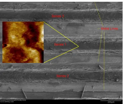
were the first to explore the plant cellulose fibrillar ultrastructure by electron microscopy. They found that essential and secondary cell walls exhibit a fibrillar texture. With respect to the molecular axis’ terminal groups reducing functionality and a nonreducing end can be distinguished (Figure 1.1.).
Figure 1.1. Molecular structure of cellulose
The glucopyranose rings have 4C1 chair conformations. Physical properties of cellulose are influenced by its supramolecular structure, namely the hydrogen bonding network. The three kinds of hydroxyl groups bond equatorially in anhydroglucose units under different polarities, and the resulting inter- and intramolecular interactions are responsible for the
stabilization, crystalline structure and hydrophilic nature of cellulose (Figure 1.2.). The H-s in the left ring serve as hydrogen bond donators, while O-s in the right ring including the glycosidic O bond contribute as hydrogen bond acceptors for the hydrogen bonding network (Figure 1.2.). In nature cellulose chain does not exist individually it is assembled of individual cellulose chains and forming fibrillary or fiber like material. In most of the higher plants cellulose is surrounded by hemicellulose and lignin matrix.
Around 36 linear β-1-4-linked glucan chains form subfibrils (2-20 nm in diameter), which consist of repeating ordered (crystalline) and not ordered (amorphous or chain dislocations) parts in the fringed fibril theory. Pure cellulose subfibrils exist in bacterial cellulose and valonia only.
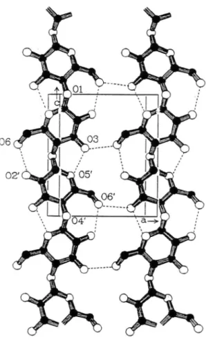
Figure 1.2. Most probable hydrogen bond pattern of cellulose I. (Kolpak and Blackwell 1976, 1978)
In the ordered cellulose chain region, strong and complex inter and intra molecular hydrogen-bond network formed. Hence cellulose subfibrils has different crystalline polymorphs. In native cellulose (cellulose I) found in nature, there are two intramolecular hydrogen bonds, which are between the OH-3···O5΄, and between the OH-2··· Ο6’ for bonding the layers and one intermolecular hydrogen bond, OH-6···O3 for linking the layers laterally, depending on the hydroxymethyl conformation at the C-6 position[4].
Native cellulose I consists of two distinct crystal phases, namely Iα and Iβ. The Ια/Ιβ ratio defines cellulose properties and varies within the cellulose microfibrils as well as in different cellulose sources. Algae and bacterial cellulose specimens are rich in Iα form, while cotton, wood and ramie fibers are rich in Iβ crystalline allomorph[5].
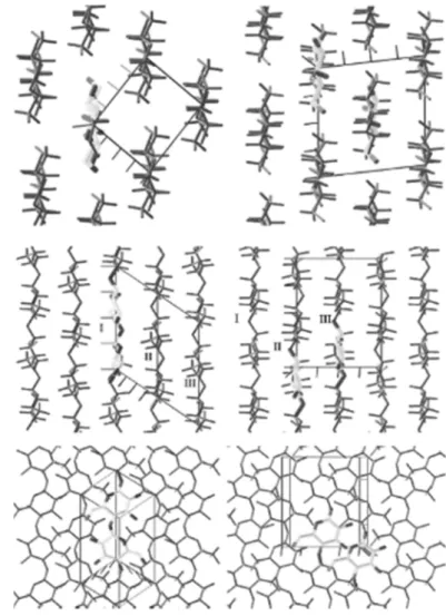
The crystal structure and hydrogen-bonding system in cellulose Iα and Iβ respectively from synchrotron X-ray and neutron fiber diffraction apparatus are shown in Figure 1.3.
Figure 1.3. Crystal structures of cellulose Iα (left) and Iβ (right). Top row: down the chain axes. Middle row: perpendicular to the chain axis and in the plane of hydrogen
In both of these structures, cellulose chains are parallel but they differ in their hydrogen bonding patterns, i.e. in the crystalline structure. Iα corresponds to a triclinic unit cell (a = 0.6717 nm, b = 0.5962 nm, c = 1.040 nm, α = 118.080, β = 114.80° and γ = 80.37°) containing two chains per unit cell, while Iβ exists in a monoclinic unit cell having one cellulose chain (a = 0.7784 nm, b = 0.8201 nm, c = 1.038 nm, α = β = 90° and γ = 96.5°). Furthermore, Iα type cellulose is metastable and can be converted irreversibly into the irreversible Iβ. Later in the Chapter 2 the Iα crystalline structure of cellulose has been used for the quantum mechanical polarization calculation, which has not been calculated in this context earlier.
Chemical, physical and enzymatic degradation of fibrillary cellulose fibers led to a colloidal suspension, which was observed by electron microscopy in 1950s as has been mentioned earlier. The observed degradation product was a needle-shaped crystalline cellulose particles having identical crystalline structure as the original fiber or fibrils. After the acid hydrolysis conditions were optimized, Marchessault et al.[7] demonstrated that colloidal suspensions of cellulose nanocrystals (above a certain concentration) exhibited nematic liquid crystalline alignment, so the nanocrystals not randomly oriented in the liquid media. That observation helped later to explore the orientation of cellulose nanocrystals in thin films or surface functional modification. Chiral nematic alignment was one of the first natural film forming ability of CNCs colloid producing different colors under polarized light. The orientation of the CNCs is slightly different at each of the nematic planes due to rotation of the magnetic direction about the perpendicular cholesteric axis[8]. Taking advantage of such phenomena, several techniques have been used in attempts to control the alignment of CNCs. These techniques include the rotational shearing of gels[9] and the application of intense magnetic[10,11] and electric fields[12-14]. However, these techniques are time consuming and expensive, especially because the requirement of high (electric or magnetic) fields. Additionally, control over the thickness of the final films is not easily accomplished, nor the extension of the films. Most of these mentioned techniques resulted oriented cellulose nanocrystals on a drop size area only. A recent study of cellulose nanocrystal thin films demonstrated birefringence to be a result of intrinsic shape and optical anisotropy of rod-like cellulose nanocrystals, oriented by a spin- coating process. Birefringence varied with thickness and relative location to
the spin axis, allowing preparation of solid samples ordered for maximally anisotropy[15].
Using the crude cellulase enzyme from Trichoderma viride, positive- and negative-type cellulose spherulites can be formed by artificial polymerization of cellulose via cellobiosyl fluoride, as observed by optical polarization microscopy[16]. Like starch granules, spherules show optical birefringence, suggesting polymerization proceeds via two independent mechanisms. Under given polymerization conditions, the majority of the spherulites show a negative-type structure, indicating that cellulose chains within a spherulite have a predominantly tangential orientation[17]. Both the introduced film formation techniques from cellulose nanocrystals and artificial polymerization of cellobiosyl fluoride resulted diverse applications in many scientific fields.
In general, the possibility to control the architecture of two- and three- dimensional arrays of proteins, nanoparticles and nanomaterials is critical in applications related to biotechnology (vaccines, diagnostics, etc.), biosensing, electronics, optics, microengineering and electrocatalysts[17,18]. The same can be stated about the emerging utilization of CNCs as a building block for a broad range of structures, antimicrobial packaging and aerogels for wastewater treatment, drug delivery or surface coatings. In such cases the additional benefit of improved mechanical characteristics with aligned CNCs might be realized[8]. Oriented cellulose nanocrystals offer potentially increased surface mechanical strength and wear resistance. A transverse Young’s modulus, hardness and coefficient of friction of 8.3±0.9 GPa, 0.38±0.03 GPa and 0.51±0.23 respectively, were determined. Notably, the transverse Young’s modulus was found to be in agreement with reported values predicted by molecular modeling and measured for single CNCs by using atomic force microscopy, while the friction coefficient and wear resistance were enhanced and within the ranges that are useful in high performance applications[19].
Cellulose nanocrystals have been used as a reinforcing material in composites to improve their mechanical properties[20]. This is in part due to their relatively high intrinsic strength, high aspect ratio and low density. The use of CNCs in high performance coatings is attractive not only because of their expected properties but also because they may provide a platform for fundamental studies related to their assembly. When used in composites,
CNCs have been shown to affect markedly the properties of the resultant materials, depending on the processing conditions[21] and their supramolecular organization[18].
The overall aim of this chapter was to introduce and point the way forward of cellulose nanocrystal’s characteristics, some basic processing and novel film-formation properties were also briefly outlined. The author feels that this basic knowledge is imperative to comprehend the overall importance of film forming ability and utilization of CNCs. For some readers there are obvious details, for others the entire Chapter might be unfamiliar.
Nevertheless, this Introduction tried to summarize the essential features of cellulose nanocrystals with the hope that it is deep enough to provide valuable facts and information and short enough to avoid redundancies and tediousness. In the following sections further solutions are extended related to CNCs thin films, properties and applications by transforming them into a more formalized order, which attempts to address the following objectives:
i) To develop of highly oriented cellulose nanocrystals and nanofibrillar films by calculating the dielectrophoretic and polarizability properties (electric field strength and frequency) using the Clausius-Mossotti approach.
ii) To calculate the polarizability of the unit cellulose nanocrystal using quantum mechanical approach at subnanometer level.
iii) To experimentally measure the piezoelectric response of the highly aligned cellulose nanocrystal thin films.
iv) To develop and validate a finite element simulation (eigenfrequency analysis) of a piezoelectric cantilever.
v) To fabricate bacterial cellulose nanofibrillar self-standing films for energy harvesting applications from bacterial cellulose.
The results of the theoretical, analytical and experimental works are presented in each chapter separately and are summarized in form of new scientific results at the end of the chapters.
Part of this general introduction chapter has been published by our research group in Acta Histochemica Vol. 115, pages 22-31, in 2013, in Cellulose Vol. 22, pages 779-788, in 2015, and in a Tappi Press published book chapter and some other journal listed in the references.
The potential benefits that can be gained through the formation of aligned CNC films are expected to broaden the possible applications of such sustainable, biologically-derived material. One of the most important emerging area of aligned cellulose nanocrystals or nanofibrils is in micro- energy harvesting systems. Energy harvesting systems made from cellulose is capable of scavenging milliwatts from solar, vibrational, thermal[22] and biological sources. Our recently published works report micro-energy harvesting technologies, one based on vibrational piezoelectric[23,24] system and the other one is based on solar energy[25], which capable scavenging of 12 µW/cm2 energy in indoor environment.
1.1. References
1. J.F. Kennedy, C.A. White, In: Barton D, Ollis WD, Haslam E (eds) Comprehensive organic chemistry. Pergamon, Oxford 1979;5:755
2. Payen, A. Compt. Rend. 1838, 7, 1052.
3. A. Frey-Wyssling, K. Mühlethaler, R.G.W. Wyckoff, Exprimentia 4 (1948) 475-476.
4. T. Kondo, Chapter 3. Hydrogen bonds in cellulose and cellulose derivatives. Polysaccharides: Structural diversity and functional versatility.
1st edition, Marcel Dekker Inc., 2004, 69-98.
5. Y. Habibi, L.A. Lucia, O.J. Rojas, Chemical Reviews, 110 (6) (2010) 3479-3500.
6. Y. Nishiyama, J. Sugiyama, H. Chanzy, P. Langan, J. Am. Chem. Soc., 125 (47) (2003) 14300-14306.
7. R. H. Marchessault, F.F. Morehead, N.M. Walter, Nature, 184 (1959) 632.
8. K. Fleming, D. G. Gray, S. Matthews, Chemistry-a European Journal 7, (9) (2001) 1831-1835.
9. N. Yoshiharu, K. Shigenori, W. Masahisa, O. Takeshi, Macromolecules, 30, (1997) 6395-6397.
10. J.F. Revol, L. Godbout, X.M. Dong, D.G. Gray, H. Chanzy, G. Maret, Liq. Cryst. 16 (1994) 127.
11. E.D. Cranston, D.G. Gray, Science and Technology of Advanced Materials, 7 (2006) 319-321.
12. Sugiyama, J.; Chanzy, H.; Maret, G., Orientation of cellulose microcrystals by strong magnetic-fields. Macromolecules 1992, 25, (16), 4232-4234.
13. D. Bordel, D. J.L. Putaux, L. Heux, Langmuir, 22, (11) (2006) 4899- 4901.
14. Y. Habibi, T. Heim, R. Douillard, Journal of Polymer Science Part B- Polymer Physics, 46, (14) (2008) 1430-1436.
15. E.D. Cranston, D.G. Gray, Colloids and Surfaces A: Physicochemical and Engineering Aspects 325 (2008) 44-51.
16. S. Kobayashi, L.J. Hobson, J. Sakamoto, S. Kimura, J. Sugiyama, T.
Imai, T. Itoh, Biomacromolecules 1(2000) 168-173.
17. W. Helbert, H. Chanzy, V. Planchot, A. Buleon, P. Colonna, International Journal of Biological Macromolecules 15 (1993) 183-187.
18. C. M. Niemeyer, Angewandte Chemie-International Edition 40, (22) (2001) 4128-4158.
19. Ingrid Hoeger, PhD, “Ultrathin Films of Cellulose and Lignin for Studies on Interfacial Phenomena”. Supervisors: Orlando J. Rojas and Steve Kelley, NC State, 2011.
20. K. Oksman, A.P.Mathew, D. Bondeson, I. Kvien, Composite Science and Technology, 66 (2006) 2776–2784.
21. T. Ebeling, M. Paillet, R. Borsali, O. Diat, A. Dufresne, J. Y. Cavaille, H. Chanzy, Langmuir 15, (19) (1999) 6123-6126.
22. V. Nagy, I. Suleimanov, G. Molnár, L. Salmon, A. Bousseksou, L. Csoka, J Mat Chem C 3 (2015) 7897.
23. L. Csoka, I.C. Hoeger, O.J. Rojas, I. Peszlen, J.J. Pawlak, P.N. Peralta, ACS Macro Letter (2012), 867.
24. I.C Hoeger, L. Csoka, O.J. Rojas, Assembly of CNC in Coatings for Mechanical, Piezoelectric and Biosensing Applications. In: Michael T Postek, Robert J Moon, Alan W Rudie, Michael A Bilodeau (ed). Production and Applications of Cellulose Nanomaterials. Atlanta: TAPPI Press, 2013. pp.
71-74. (ISBN: 978-1-59510-224-9)
25. L. Csoka, D. Dudic, I. Petronijevic, C. Rozsa, K. Halasz, V. Djokovic, Cellulose 22 (2015) 779.
Dielectrophoresis of cellulose nanocrystals
2.1. Introduction
Ultrathin films of cellulose nanocrystals (CNCs) produced by controlled assembly have gained recent attention not only because of a number of emerging applications such as fabrication of advanced materials but also due to the fact that they can be used to better understand the nature of complex interactions in related systems.[1-5]
Self-assembly of high aspect-ratio nanoparticles, such as CNCs, is facilitated by their geometry, dimensions, surface and intermolecular interaction forces and, from their response to external (electric and/or magnetic) fields. For example, convection-driven assembly has been used in coatings with spherical nano- and micro-particles.[6,7] Highly crystalline CNCs obtained after their cleavage from the cell wall of fibers[8-10] allows the creation of functional systems via simple and inexpensive self-assembly.
Ultrathin films of cellulose nanocrystals (CNCs) have been developed by using the Langmuir-Schaeffer (LS) lifting[11] and also the convective/shear assembly (CSA) techniques.[12,13] The resulting structures were found to be isotropic in the case of the LS method, while the CSA films comprised aligned CNCs. In the latter approach, orientation was achieved by a subtle balance of effects that included nanoparticle geometry (aspect ratio, mainly), surface charge density of the CNCs and the substrate, surface tension forces and withdrawal rate in the CSA setup.[12,13] Directed assembly of CNCs and microcrystals has been carried out using external electric,[4,5,14-16] magnetic[17-
20] and shear fields.[2,13,21] However, such external fields have had limited success in producing highly oriented CNCs within these films. Compared to magnetic fields, application of electric fields typically requires less energy.
Furthermore, the fact that alternating current (AC) can be used opens additional opportunities for manipulation of particle orientation.
Shear alignment of CNCs in a convective assembly setup was shown to be an effective, inexpensive and scalable method.[13] However, improved control of orientation, faster processing and improved particle alignment, optimization are desirable. Therefore, we propose the fabrication of ultrathin films of highly oriented CNCs by using a convective/shear forces coupled with low intensity electric fields. Indeed, the second aim of this chapter was to present the polarization calculation based on quantum- mechanical approach. In this respect, a classical molecular evaluation by dipole moments also included to get a better physical insight into such phenomena in an extended mode on cellulose nanocrystals.
Given the highlighted objectives, the first part of this chapter resulted one peer reviewed scientific publication in Journal of Colloid and Interface Science (a Q1 qualified journal), Vol. 363 in 2011, pages: 206–212 and three presentations at scientific symposia at 241st ACS Annual Conference, Los Angeles, CA, USA in 2011 and at 13th International Conference on Organized Molecular Films, Quebec City, Canada, July 18-21, in 2010 and at International Conference on Nanotechnology for the Forest Products Industry, Espoo, Finland, Tappi Press, in 2010, ISBN:9781618390011.
The second part of that chapter has been worked out as an extension of the previous work using the quantum mechanical approach for the polarization calculation of cellulose nanocrystal.
2.2. Materials and methods
2.2.1 Materials
Ramie fibers from Stucken Melchers GmbH & Co., Germany, were used in the production of cellulose nanocrystals. The fibers were cut in small pieces and purified with a Soxhlet extraction system and then hydrolyzed with 65
% sulfuric acid at 55 °C for 30 min under continuous stirring. The resulting suspension was filtered through a sintered Buchner funnel, washed with deionized water and recovered by subsequent centrifugations at 10,000 rpm (10 °C) for 10 min each. Finally the resulting suspension was dialyzed against deionized water and then against Milli-Q water for a few weeks. The obtained CNC suspension was stored at 4°C until use. The dimensions of the
CNCs were 185± 25 nm in length and 6.5 ± 0.7 nm in width, as determined by transmission electron microscopy [22]. Deionized water from an ion- exchange system (Pureflow, Inc.) followed by treatment in a Milli-Q®
Gradient unit with a resultant resistivity of >18 MΩ•cm was used in all experiments. The particles were confirmed to be 88% crystalline as determined by WAXS. In theoretical consideration NFC (nano fibrillated cellulose) was also included in the calculation to see the effect of different dimensions of the particle up to 1000 nm.
2.2.2 Preparation of CNC films
Aqueous CNC suspensions of 2.5 wt% concentration were used in all particle deposition experiments by using a withdrawal speed of 8.4 cmh-1, which was found to be optimal for obtaining highly oriented films[12,13]. The CNC films were created in a convective assembly setup combined with an AC electric field. The AC electric field was generated by a power amplifier (Krohn-Hite Model 7500-DC to 1 MHz wideband power amplifier, Krohn-Hite Corp., Brockton, MA) driven by a sine wave from a function generator (Wavetek Model 134, Wavetek Corp., San Diego, CA). The reported voltages are peak-to-peak values.
Microscope glass slides were used as support for thin sheets of freshly cleaved mica which were used as a carrier of the CNC film. To this end mica sheets were gently glued onto the glass slides and the topmost layer was peeled off to uncover a clean, pristine mica surface. Before CNC assembly, the glass-mica carrier was treated with a 500 ppm polyethyleneimine (PEI) solution, which made cationic charges available for electrostatic interactions with the negatively charged CNCs. In the course of convective self-assembly, a droplet (ca. 20µl) of liquid suspension was placed in the wedge formed by a tilted (24°) glass slide and the mica carrier (Figure 2.1). The CNC suspension was held by capillary forces and the liquid meniscus was withdrawn horizontally across the mica carrier by translating the tilted glass slide. This translation was produced with a syringe pump (NE-500 New era pump systems, Inc, Wantagh, NY) that moved the tilted glass at a constant speed of 8.4 cmh-1. To create the constant AC electric field around the mica carrier, two parallel aluminum electrodes spaced 5 mm apart from each other were placed on the edges of the mica sheet and connected to a power amplifier
(see Figure 2.1). The CNC film deposition was carried out at room humidity and temperature.
Figure 2.1. Schematic illustration of the convective assembly setup coupled with an electric field. In a typical experiment, a volume of CNC suspension was placed between a tilted, deposition glass slide and a base substrate consisting of mica with pre-adsorbed PEI (polyethyleneimine) and supported on a glass slide. The distance between the aluminum electrodes was 5 mm and withdrawal of the deposition glass slide occurred in the horizontal direction at a constant speed (v) of 8.4 cmh-1
The system was driven by a computer, allowing precise control of the withdrawal speed. The alignment of CNCs in the obtained ultrathin films with application of AC electric fields was examined at field strengths of 100, 400 and 800 Vcm-1 and frequencies of 200 and 2000 Hz. The results were compared against assemblies obtained in the absence of external electric fields. The typical thicknesses of the deposited films were ca. 38 nm, as measured by ellipsometry.
A Matlab code was used to determine the degree of CNC alignment. AFM height images were used to perform grain partition and filtering and the resulting images were analyzed for the angles of the long axis of the CNCs with respect to a reference line in the withdrawal direction. The degree of CNC alignment was defined as the number % of CNCs in the angle range between 0 and 20 degrees in the withdrawal direction considering symmetry conditions. Typically, more than 300 CNCs were counted in image processing and at least 3 different locations, from the different films were
Signal
Mica
Al electrodes
Deposition glass slide
Base substrate glass slide v
analyzed for each condition. More details about this method can be found in Ref. [13].
An AFM XE 100 from Park Systems (Santa Clara, CA) was used in non- contact mode to obtain topographic images of the surface. A pyramidal silicon tip with a radius of less than 10 nm and an aluminum coating on the backside (Park Systems, Santa Clara, CA) was used with an applied constant force of 42 Nm-1 and a frequency of 330 KHz. At least three different films at three different positions were imaged for each deposition condition used. The images were analyzed using the XEI software, and only flattening of one regression order was used to correct the slope of the tip/sample interaction.
To apply a style, begin by selecting the text to which the style needs to be applied, and then choose the style name from the styles list box on the tool bar or by using WSPC Toolbar. The WSPC templates contain all the styles that are required for formatting the documents. It is crucial and recommended to exploit the usage of styles as much as possible to format the text. However, apply direct formatting only as a last resort when the style, for some reason, is incompatible with the requisite. As a note of caution, do not use any style for a purpose other than that for which it was intended or for the want of effort.
2.3. Theoretical consideration
Frequency-dependent changes in polarizability of biological cells and colloidal particles[23] take place from structural, Maxwell-Wagner polarization effects.[24-26] Dielectric models have considered the properties of the particles by assuming spherical or ellipsoidal geometries. [27,28] When colloidal particles are suspended in low conductivity medium different states of polarizability occur, less or more polarizable than the medium. These states of polarizability are frequency-dependent. At low frequencies the surface charges are expected not to affect the polarization mechanism while at high frequencies the differences in permittivity are dominant factors. [29] The charges of opposite signs on either side of the particle lead to an effective net-induced dipole moment. In dielectrophoresis (DEP), when a non-uniform electric field is applied on a dielectric particle, a force unbalance takes place, as described by Pohl in 1951. [30] Consequently the colloidal particles move
towards or away from regions of high field, depending on their polarizability relative to that of the medium. [31,32]
Similar phenomenology as the one described above is expected to offer a simple approach to align CNCs at low AC electric fields. Calculated dipole moments and the Clausius-Mossotti factors can describe the critical frequencies for alignment and the peak dielectrophoresis of CNCs. The DEP is a phenomenon where a force is exerted on a dielectric particle in a non- uniform electric field to move or rotate it in a given surrounding media. The potential at the crystal surface depends on the field frequency as well as electrical and geometrical characteristics. In this investigation a prolate spheroid geometry was assumed for the CNCs. [33,34] It was also assumed that during polarization by an external, homogeneous electric field the ellipsoid CNCs acquired only a dipolar moment; multipoles of higher orders were assumed to be absent. [35]
The dipole moment depends on the frequency of the applied electric field and the dielectric properties (permittivity and conductivity) of the particle and the fluid. [36]
The dielectric force FDEP can be described by
0
1
E
p
F
DEP= ∇
(2.1)where E0 is the applied electric field and p1 is the dipole moment. The dipole moment for an ellipsoid can be calculated by the volume integral of the polarization vector (P ), which is constant over the volume:
i i m
i a b K E
p =4
π
2ε
(2.2)where a,b stand for the major and minor half axes, respectively and the i= x, y components represents the directions projected along these axes of the particle. ε is the permittivity of the medium and Ki denote the Clausius- Mossotti (CM) factor. The complex CM factor for homogeneous ellipsoid can be written as:
) (
) (
3 ) 1 (
m i p
m
m p
i A
K ε ε ε
ε ω ε
− +
= − (2.3)
with
ω ε ε σ ε
0
−i
= (2.4)
where p and m refer to the particle and the medium, respectively. σ is the conductivity of the dielectric and ω is the angular frequency of the applied field. Ai is a component of the depolarization factor along any of the three axes of the ellipsoid (i=1, 2, 3). For a prolate ellipsoid the major axis component of the depolarization factor is given by
−
− +
= − e
e e e
Ax e 2
1 log 1 2
1
2
2 (2.5)
where e is the eccentricity:
2
1
−
= a
e b (2.6)
If the particle shape is close to spherical, e tends to unity, as expected.
Due to the symmetry of the ellipsoid of revolution, the components of the depolarization factor at the two other axes of the prolate ellipsoid (i= y, z) have the same value, given as:
2
1 x
y z
A A
A = = − (2.7)
Finally, the DEP behavior can be described using the average of the real part of the Clausius-Mossotti factor for the three possible axes of polarization:
[ ] ∑ [ ]
=
=
z y x i
K
iK
, ,
) ( 3 Re
) 1 (
Re ω ω
(2.8)On the other hand, the rotation of particles can be determined by the equilibrium of hydrodynamic and electrorotation (ER) torque, according to the imaginary part of the Clausius-Mossotti factor:
[ ] ∑ [ ]
=
=
z y x i
K
iK
, ,
) ( 3 Im
) 1 (
Im ω ω
(2.9)The nature of the particle or the type of material is critical. Of relevance to the present work are the measured dielectric properties of cellulose:
cellulose,[37] cellophane,[38] microcrystalline cellulose[39] and regenerated cellulose,[40] which have been reported to be similar (values below 0.1 MHz).
In this work the real and imaginary part of the CM factor were calculated by assuming the dielectric constants (permittivity and conductivity at given frequencies) and provided in Ref. [40]
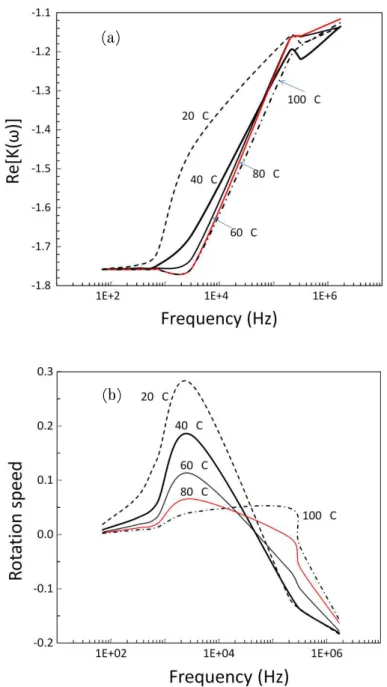
Figure 2.2 shows the real and imaginary components of the CM factor for CNCs calculated at different temperatures. Since the polarizability of CNCs is low (see Figure 2.2(a) for the real part of the Clausius-Mossotti factor), Re[Ki(ω)] becomes negative (Re[Ki(ω)]<0), and the particles are expected to move toward regions with minimum electric fields. This is called negative dielectrophoresis (n-DEP). As the water medium temperature increases the real part of the CM factor is shifted to higher frequencies but still remains in the negative dielectrophoresis (n-DEP) region. At high frequencies (beyond 103 Hz), the value of the real part of the Clausius-Mossotti factor changes sharply but remains in the n-DEP region. As can be observed in Figure 2.2(a), the calculated real part of the CM factor have no crossover frequency;
this was also the case when different medium conductivities were considered.
From Fig. 2.2b, we can assume that a frequency of the electrical field around 2 kHz can be useful for the CFCs alignment during the shear assembly.
Figure 2.2. Real (a) and imaginary (b) components of the Clausius-Mossotti factor as a function of the frequency of the electric field applied to CNCs. The CNCs were modeled as prolate ellipsoids and suspended in aqueous medium.
(a)
(b)
The b/a ratio was found to play a minor role in nanoparticle rotation rates, changes by no more than tenths of a percent were calculated. This result is explained by the fact that the reduction in the moment of electrical forces (polarization in the direction normal to the symmetry axis decreases for elongated ellipsoids) is compensated by a diminishing viscous friction.[26,41]
In the 20-100 ºC temperature range the peaks of the electro-rotation (ER) spectrum of CNCs shifted linearly to higher frequencies with T (see Figure 2.2(b)). This is due to the inverse temperature dependence of permittivity and conductivity. When the temperature is increased, the intermolecular forces become less dominant and the particles are more unrestricted to respond to the applied electric field, thus giving a shifted peak at higher field frequency. A temperature of 25 °C was used in further theoretical and experimental considerations (no significant changes with temperature of the medium were observed).
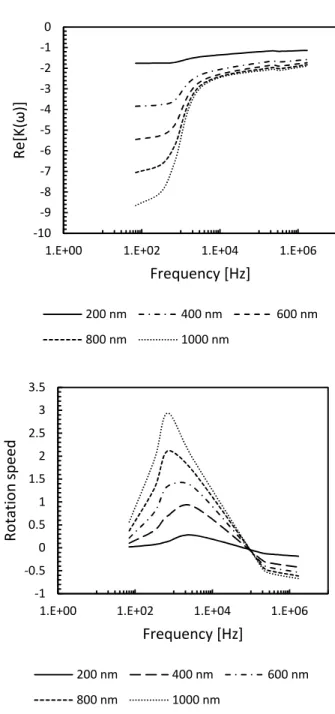
Fig. 2.3 shows the real and imaginary components of the Clausius- Mossotti (CM) factor for NFCs calculated at different lengths. Since the polarizability of NFCs is low, same as CNCs (see Fig. 2.3a for the real part of the Clausius–Mossotti factor), Re[Ki(ω)] becomes negative (Re [Ki(ω)] <
0), and the particles are expected to move toward regions with minimum electric fields similar to CNCs. As the length of NFCs increases (the diameter stay 20 nm for each), the real part of the CM factor is shifted to higher frequencies but still remains in the negative dielectrophoresis (n-DEP) region. At high frequencies (beyond 700 Hz), the value of the real part of the Clausius– Mossotti factor changes sharply but remains in the n-DEP region.
As can be observed in Fig. 3a, the calculated real part of the CM factor have no crossover frequency.
In the 200–1000 nm length range, the peaks of the electrorotation (ER) spectrum of NFCs shifted linearly to lower frequencies with length (see Fig.
3b). But the magnitude of the rotation speed in increased compare to CNCs.
From Fig. 2.3b, we can assume that a frequency of the electrical field between 700-1000 Hz can be useful for the NFCs alignment during the shear assembly, which is rougly the half than can be used for CNCs.
Figure 2.3. Real (a) and imaginary (b) components of the Clausius-Mossotti factor as a function of the frequency of the electric field applied to NFCs.
-10 -9 -8 -7 -6 -5 -4 -3 -2 -1 0
1.E+00 1.E+02 1.E+04 1.E+06
Re[K(ω)]
Frequency [Hz]
200 nm 400 nm 600 nm
800 nm 1000 nm
-1 -0.5 0 0.5 1 1.5 2 2.5 3 3.5
1.E+00 1.E+02 1.E+04 1.E+06
Rotation speed
Frequency [Hz]
200 nm 400 nm 600 nm
800 nm 1000 nm
In sum, the calculated polarizability of prolate objects in aqueous solution was used to describe electrophoretic phenomena of CNCs and NFCs subjected to electric fields. Resulting CM spectra for dielectric properties of homogeneous prolate ellipsoids assisted in discriminating between purely physical and temperature-induced changes, [27] and to find the optimal field strength and frequency for isotropic alignment. The polarization model introduced here was used further used to understand and control the alignment of CNCs during film formation. Results for CNC alignment in ultrathin films are described in more detail in the next section in light of the CM function. NFCs were used only in the theoretical approach showing the CM function at different length of the particle.
2.4. Results and discussion
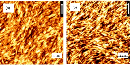
Ultrathin films of CNCs deposited on mica surfaces were observed in air by using AFM. In our earlier work CNC suspension subjected to shear/convective forces was shown to produce a disorder film on mica. Other substrates were found to favor better alignment under the experimental conditions employed. Therefore, mica as the most unfavorable substrate for CNC alignment was used in this work. This condition also helps in decoupling the effects of electric field from the complex contributions of shear and capillary forces.[13] Prior to AC field-assisted shear assembly, two reference deposition experiments, without application of electric fields, were carried out. AFM images of ultrathin film of CNCs assembled on mica and also on mica with a pre-adsorbed layer of PEI are presented in Figures 2.4a and 2.4b, respectively.
Figure 2.4. CNC films assembled on pure mica (a) and on mica with a pre-adsorbed layer of cationic PEI (b) by the CSA technique. The withdrawal direction is indicated by the arrow.
The films were produced with the AC electric field turned off.
The withdrawal direction is indicated in these figures by the respective vector which was used relative at a given angle of the applied electric field.
It can be generally concluded that shear forces created randomly oriented, anisotropic multilayers of CNCs.[13] The degree of alignment quantified by
(a)
1 µm 1 µm
(b)
the number density of CNCs in the angle range between 0 and ±20° on pure mica (Figure 2.4a) and on mica with a pre-adsorbed layer of PEI (Figure 4b), was 16 and 56%, respectively. It was noted that the data for the experimental degree of alignment had a large standard deviation owing to the disordered nature of the film.
Film formation was observed to depend on the withdrawal speed (see Experimental section) and on the rate of solvent evaporation. Mica was primed with a pre-adsorbed layer of cationic PEI, with an ellipsometric thickness of less than 1 nm. The films of CNC deposited on the mica pre- treated with PEI were multilayered, as can be determined from typical CNC film thicknesses of ca. 40 nm. More homogeneous deposition was favored in the case of the positively charged substrate. The bottom layer of CNCs was expected to bind to PEI via van der Waals and electrostatic interactions, rather than by forming crosslinked networks.[42] Such anchored layer likely worked as an insulation and under an AC electric field it facilitated alignment of CNCs in the upper layers. In fact, the PEI adsorbed layer was shown to facilitate a linear growth of ultrathin films of CNCs.
During deposition, the withdrawal speed must be matched with that of the settling particles so as to maintain a continuous and homogeneous film consolidation. Moreover, the deposition surface must be wetted by the CNC suspension in order to enable sliding on the substrate, to maintain a constant evaporation rate and to form a stable film.[43] At high evaporation rates instabilities in the growth of the structure, for example rupture or stripping of the film, may occur.[44]
In the experiments the evaporation rate decreased linearly with time and therefore the formation of structured assemblies improved after some withdrawal distance from the initiation of the deposition, i.e., at a distance from the edge of the deposited film of CNCs.
In contrast to the randomly oriented CNC film shown in Figure 2.4, application of an external electric field induced CNC orientation. For example, Figure 2.5 shows aligned nanoparticles on mica with pre-adsorbed PEI in films obtained by shear assembly coupled with an electric field of 100 Vcm-1 AC and 2 kHz frequency.
Figure 2.5. AFM height image of an ultrathin film of CNCs assembled under an electric field of 100 Vcm-1 and 2 kHz frequency. The electric field vector is perpendicular to the withdrawal direction, which is indicated by the arrow.
In the experiments illustrated in Figure 2.5 the electric field was directed perpendicular to the withdrawal direction. However, by changing the field strength and frequency the orientation direction could be altered according to the bivariate map for the orientation parameter (Op) shown in Figure 2.6.
In this figure the polarizability of CNCs is presented as a function of field strength and frequency.
1 µm
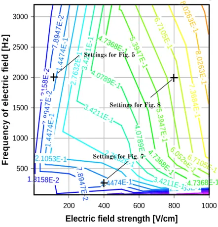
Figure 2.6. Magnitude of the orientation parameter (Op) of CNCs as a function of field strength and frequency. This bivariate map was plotted using DPlot Graph software, according to the equations described in the text. Crosses are drawn at frequency-field strength conditions used in experiments that yielded films illustrated in Figures 2.5, 2.7 and 2.8.
The effective polarizability is the proportionality constant in the linear relationship between the induced dipole moment and the external field. More specifically, dipoles and particles such as CNCs have a special form of polarization, on account of the Maxwell-Boltzmann distribution (MBd); the dipoles can be oriented in such a way to have a net dipole moment along the direction of the field.
200 400 600 800 1000
500 1000 1500 2000 2500 3000
Electric field strength [V/cm]
Frequency of electric field [Hz]
Calculated values of the oriented order parameter
1.3158E-2 1.3158E-2
7.8947E-2
7.8 94
7E -2 7.8947E-2
1.4474E-1
1.4474E-1 1.4474E-1
2.1053E-1
2.1053E-1 2.7632E-1
2.7632E-1
3.4211E-1 3.4211E-1
3.4211E-1 4.0789E-1
4.0 78
9E -1 4.7368E-1
4.7368E-1 4.736
8E-1 5.3
94 7E
-1 5.39
47 E-1
6.052
6E6.71-1 05E-1 6.710
5E -1
7.3 68
4E -1 8.0
26 3E
-1 8.0
26 3E
-1
Settings for Fig. 7 Settings for Fig. 8 Settings for Fig. 5
The component of the external electric field direction of the dipole moment can be calculated from Eq. 2.10:
θ
icos
−p (2.10)
and the potential energy of a dipole in an electric field can be calculated as the real part of the scalar product in Eq. 2.11:
) . ( )
( A pE
V
θ
=− ℜ (2.11)where A is a factor that can be used to adjust the theoretical model to the numerical data and θ is the angle between the dipole axis of the particle and the direction of electric field.[45]
If all orientations in water medium were equally likely, the average component along the field would be zero.[45] But on account of the MBd, the probability (P) of finding the dipole axis is proportional to: [46]
π θ θ
θ
d e P e
kT V
kT V
MBd
∫
−−
= 2
0 ) (
) (
(2.12)
where k is the Boltzman’s constant, and T the temperature. Hence, the orientation parameter (Op) can be calculated by integration of the MBd over solid angles:
θ
π θ
d P
Op =
∫
MBd2
0
2
cos (2.13)
This function (Eq. 2.13) is proportional to the external field in the bivariate plot shown in Figure 2.5. It can be seen that at low field strength and frequency the mean dipole moment is proportional to the field and the polarizability and the dipoles are oriented antiparallel to the electric field, as was the case observed in Figure 2.7. Over the inflection point (at a value of
Op of 0.407, Fig. 2.6) high field saturation starts to take place and all the dipoles are parallel to the external field.
At low-frequency AC fields, particle polarization and interactions are controlled by the particle and fluid conductivities.[47] This effect is frequency- dependent in the case of cellulose in aqueous medium.[40] At high-frequency AC fields, the charges have insufficient time to respond and orientation polarization is dominant; conductivity no longer plays a role.[48-50] In the present case of low–to–medium frequencies, both the permittivity and conductivity are important.
In order to further illustrate the implications of the bivariate map shown in Figure 2.6, a series of experiments were conducted to validate the predictions for the direction and degree of alignment. Moreover, image analyses were performed on AFM scans using a MATLAB code to calculate the alignment of CNC particles according to Op (reported here as % number density of particles in the 0 - ±20° leading angle range). The alignment of CNC particles at low intensity electric field and frequency (400 Vcm-1 and 200 Hz) was 46 %; at low intensity electric field and high frequency (100 Vcm-1 and 2000 Hz) it was 77 %. At high intensity electric field and frequency (800 Vcm-1 and 2000 Hz) it was 88 %. The combination of electric fields and shear forces that favored alignment in the same direction produced nearly perfect orientation of CNCs in the film.
Figure 2.7 shows an AFM scan of the end section of a CNC film deposited on mica with pre-adsorbed PEI and obtained by shear assembly assisted with an electric field of 400 Vcm-1 AC and 200 Hz frequency. In this arrangement anisotropy and some degree of alignment was observed in the section close to the edge. For this field strength and frequency range the particles were expected to align perpendicular to the electric field (see bivariate map in Figure 2.6).
Figure 2.7. AFM height image end sections of ultrathin film of CNCs formed under an electric field of 400 Vcm-1 and 200 Hz. The preferred alignment is parallel to the withdrawal direction, indicated by the arrow. The length of the deposited CNCs film on mica with pre-adsorbed PEI was 5 cm.
In contrast, when the electric field strength and frequency were increased, the CNCs tended to align parallel to the field direction, as shown in Figure 2.8. Highly oriented, anisotropic structures were observed in the middle section of the film.
If simultaneously the AC electric field and frequency are decreased, the magnitude of the induced dipole moment of the CNCs also decreases and the field-induced rotational torque is not large enough to overcome thermal forces. Consequently, the isotropic phase grows and eventually spans the entire frequency range.[51]
1 µm
Figure 2.8. AFM height image of the middle sections of ultrathin film of CNCs formed under an electric field of 800 Vcm-1 and 2000 Hz. The alignment of particles produced a highly oriented structure. The electric field vector in this case is perpendicular to the withdrawal direction, indicated by the arrow.
It was observed that over large scanned areas the ultrathin films of CNCs exhibited ordered and disordered domains. This can be explained by the polydispersity of the particle suspension or nanocrystal aggregates which created instabilities in the alignment, during film deposition. Different particle geometries can also cause some dislocations or multilayer formation.
However, the developed technique for ultrathin film coating showed that the process of alignment was stable for the middle part of the film and that dislocations were damped with the progress of film deposition (steady state conditions) and also by the decreasing CNC volume fraction as solvent evaporation occurs (in the meniscus formed between the substrate and the moving plate, see Experimental).
The effect of geometry and size of CNCs are expected to be relevant. Such variables may affect water evaporation rate and explain the inhomogeneous volume fraction during the shear assembly and also the formation of aggregates after deposition. In order to obtain a more direct understanding of such effects, further experiments with CNCs of different average size and size distributions must be performed.
1
The main parameters that affect the formation of ultrathin films are accounted in Dimitrov and Nagayama equation: [43]
) 1 )(
1
(
β ξ ϕ ϕ
−
= − h
vc lje (2.14)
where ξ and h are the porosity and height of the deposited colloidal crystal, φ is the volume fraction of the particles in suspensions, je is the evaporation flux, and l is the evaporation length (which is the integral of total evaporation flux per unit length). β is an interaction parameter that relates to the mean solvent velocity to the mean particle speed before entering the drying domain[52] and takes values between 0 and 1. β depends on the particle-particle and particle-substrate interaction: the stronger the interaction, the smaller β will be. PEI treatment of mica decreased β relative to the value for bare mica. It can be concluded that reducing the withdrawal speed may increase the alignment further, as calculated for the evaporation length by using 0.74 for the density of packed ellipsoids and considering that water evaporation flux per unit length did not depend on the particle diameter (l≈4.2 cm for 8.4 cmh-1).
Deposition speed exceeding the natural assembly rate of a monolayer, as described by Eq. 2.14, results in incompletely ordered films.[53] If the ambient air around the deposition plate is not saturated by water vapor, fast, ordered assembly is expected to take place under electric fields (Fig. 2.8).
The primary driving force for the convective transfer of CNC particles is the water evaporation from the freshly formed aligned CNC film. The volume of the CNC suspension decreases with the withdrawal motion and the film thins out gradually, as the water evaporates. Unsaturated air with water vapor around the forming film causes influx from the meniscus toward the formed film. This influx compensates the evaporation of water from the film and particle flux makes a dense, aligned CNC film under the electric field.
The particle flux is obviously stronger than the migration effect of low voltage electric field and, as stated, CNCs are subject to negative dielectrophoresis (the particles tend to align at low electric fields). Because the AC voltage is maintained in the entire withdrawal shear process, until the water is evaporated, the densely packed alignment cannot change further.
The model handles simultaneously the dielectric properties of CNCs and water medium around it. When water evaporates to unsaturated ambient air, the ratio between the dielectric materials will change. Hence the formation of the aligned CNC film is irreversible when the proper amount of water evaporates.
Using the theoretical consideration above (eq.2.1-2.9) a finite element model has been built up to effectively simulate the dielectrophoretic behavior of CNCs on a lab-on-a-chip device. With that dielectrophoretic approach the CNC particles can be shorted, separated and also control the film formation.
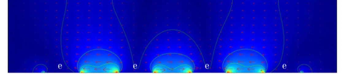
In the following section we demonstrate the fabrication of periodic and alternate, short particles using n-DEP. The Clausius-Mossotti principle behind is schematically depicted in Fig. 2.9.
Figure 2.9. Principle of shorting CNCs with a microfluidic device. A cross sectional view of the electrical field strength formed around the electrodes (e). Bright areas corresponding to higher electric field appear at both edges and surfaces of the electrodes.
An integrated array electrode with four independent microelectrode subunits (200 µm wide and ~100 µm distance between them) was fabricated as a template to short CNCs. In the present system, the n-DEP force is induced by applying an AC voltage and frequency (optimized above) to align CNCs toward a weaker region of electric field strength. These regions are indicated by light blue between the electrodes at the bottom of the image (Fig.2.9.). The CNCs were guided apart from the high electric field regions (from the edges of the electrodes and from their surface). Dielectrophoretic patterning was observed under a AFM microscope after drying the patterned CNC film.
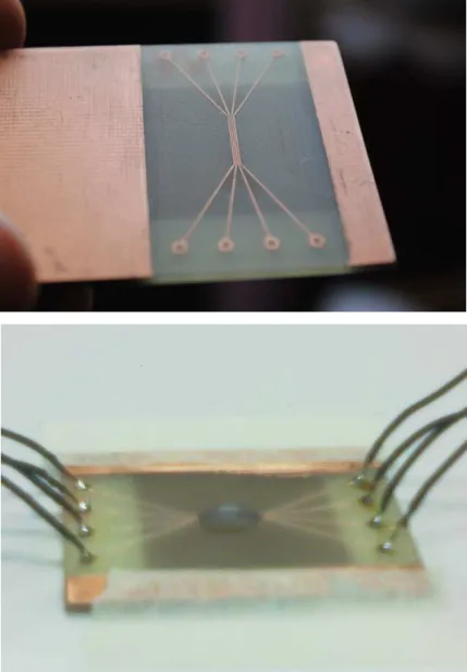
The following 2 images (Fig.2.10. a and b) show the built n-DEP type chip device with the CNC suspension on it (Fig.2.10.b).
e e e e
Figure 2.10: a and b. A modeled microfluidic device after fabrication (a) and with CNC suspension and AC connections.
The strength of the AC electric field was visualized using Comsol Multiphysics finite element software package. Fig. 2.9 clearly shows that deep valleys of electric fields are created above the electrodes and high mountains between the bands. Thus, suspended CNC particles moved to that areas (between the bands) in the n-DEP electrical and frequency region.
When the water evaporated the low electric field regions was observed by AFM microscopy. It can be clearly seen in Fig. 2.11. that the n-DEP region of the device were loaded with aligned CNCs.
Figure 2.11. AFM image about the patterned CNCs between the electrodes.
In sum, the polarizability of CNCs has been considered in an electric field, and used to interpret CNC alignment in a convective assembly setup that induced shear forces during withdrawal of the deposition plate. While this is clearly an approximation to describe the highly complex system involved, it was useful to explain the origins of highly ordered CNC structures assembled on flat surfaces. Most importantly, the proposed methods enabled the production of continuous films, which is in clear contrast to previous efforts.
Finally, it is hoped that the results will help on-chip manipulation and further assembly of CNCs with n-DEP forces.[54]
2.5. Spontaneous polarization of cellulose nanocrystals using quantum- mechanical approach
Beside the well-known Clausius-Mossotti polarization calculation powerful and accurate ab inito quantum-mechanical methods have been developed for the calculation of piezoelectric response of different materials. The latter method includes also the polarization calculation, but with a different approach. The Clausius-Mossotti polarization calculation predict physical properties of biological cells and inorganic particles as well with a homogeneous discrete properties of a colloid like particle. The quantum- mechanical method uses individual, elemental crystal properties, which exploit the theory of Berry phases developed by Vanderbilt[55,56], Resta[57]
and co-workers.
Two dependent non-zero piezoelectric constants ( = ) in the monoclinic and triclinic phase characterize the full piezoelectric tensor of such cellulose nanocrystals. The calculation of shear components of the phases have never been included in previous work. It therefore important to fill this gap and to compute the full piezoelectric tensor of cellulose nanocrystals.
The second aim of this paragraph was to compare the piezoelectric behavior of the cellulose nanocrystals with the experimental results obtained from cellulose nanocrystal thin film piezo evaluation.
The quantum-mechanical method is based on the periodic linear combination of atomic orbitals (LCAO) approach, where crystalline orbitals are expanded over the basis sets of localized functions (atomic orbitals)[58], which means that molecular orbitals are formed as a linear combination of atomic orbitals:
= ∑ (2.15) where is the i-th molecular orbital, are the coefficients of linear combination, is the µ-th atomic orbital, and is the number of atomic orbitals, which are solutions of Hartree-Fock equations (a wave functions for a single electron in the atom).
In the calculation all of the atomic orbital sets was employed with different Gaussian contractions and eigenvalues and eigenfunctions were calculated by the Hartree-Fock (HF) and Density-Functional-Theory (DFT)
Hamiltonians functions. The Berry phase’s theory (BP) of polarization were calculated according to the following equation (2.16):
( )= (2 /| |) ∙ ∗ = ( /4 ) ∑ ! < # ($)|−& ∗∇$|# ($) > )$(2.16) where is the direct unit-cell volume (333.378 Å+for triclinic unit cell of cellulose), | | is the electron charge, ∗ is the h-th reciprocal lattice basis vector, n is the electron band index, $ is the wave vector in the first Brillouin zone, and # (., $) = ψ (., $) exp(&$ ∙ .), where ψ (., $) is the n-th crystalline orbital (eigenfunction of the one-electron Hamiltonian).
The lattice constants (in Å) of triclinic unit cell of cellulose (Fig. 2.9.) used in the calculations are as follows: 4 = 10.4001, 8 = 6.7176, = 5.9627, = = 80.375°, A = 118.085°, B = 114,805°[2]. The polarization is calculated in the transverse direction at zero electric field by a uniform shear strain. The sign of piezoelectric tensor is fixed assuming that the positive direction of C and D axis goes from the cation to the anion.
Figure 2.9. The figure shows a triclinic cellulose unit cell arrangement according to Nishiyama et al. 1997.