Vapor Reheat Distillation
TEYNHAM WOODWARD
I. Introduction 1 1 8 A . General Description 1 1 8
B. Heat Requirements for a Specific Case 1 2 0 C. Heat Requirements for the General Case 121 D . Comparison of V a p o r Reheat with Other Multistage Flash Systems . . . . 124
E. Advantages and Disadvantages of V a p o r Reheat 125 II. Structural Features of Flash Chambers and Condensers 126
A . General Requirements 126 B. M e t h o d s of Producing Surface for Condensation 127
C. Advantages and Disadvantages of Various Channel Configurations . . . . 129
D . Experimental Transfer Coefficients 1 3 0 E. A r e a of Condensing Surface Required 134 III. L i q u i d - L i q u i d Heat Exchangers 1 3 4
A . General Description 1 3 4 B. Requirements of Heat-Exchange Liquids 1 3 4
C. Hydrocarbons as Heat-Exchange Liquids 134 D . Objectionable Properties of Hydrocarbons 135 E. Construction of Heat Exchangers 137 F. Materials of Construction 1 3 7 G. Dispersion Plates 1 3 7 H. Operation of S p r a y C o l u m n s 138
I. Heat-Transfer Data Obtained 1 4 0 J . Operating Difficulties 142 K. Heat-Exchanger Systems for Large S e a - W a t e r Conversion Plants . . . . 143
L. Energy Required to Circulate Oil and W a t e r in Heat Exchangers 144
IV. Economics of the V a p o r Reheat Process 145
A . General 145 B. Flash Chambers and Condensers 146
C. Heat Exchangers 146 D . Cost Comparison of V a p o r Reheat and Multistage Flash 147
List of S y m b o l s 149 References 1 5 0
117
L Introduction
The basic concepts of the vapor reheat distillation system were developed independently by several people. Donald Othmer of Brooklyn Polytechnical Institute was the first to point out the potential advantages of the system to the Office of Saline Water sometime in 1 9 5 6 . 1 proposed the system on April 25, 1957 without any knowledge of Othmer's work.
On August 20, 1957, a patent was issued to P.H. Thomas (U.S.2,803,589).
This patent describes a particular form of the vapor reheat system in considerable detail. The filing date, December 3, 1952, suggests that Thomas was the original inventor.
A . GENERAL DESCRIPTION
This system of desalination is similar, in several respects, to multistage flash currently used in several successful sea-water conversion plants.
This method has been discussed in detail in Chapter 3. T o facilitate comparison with the vapor reheat system, greatly simplified flow diagrams of the two processes are shown in Fig. 4.1 and 4.2, respectively.
1 2
• •
• •
1
: Brine out, tB ’"P^
Product, t8-
F I G . 4 . 1 . Multistage flash distillation system.
In a typical multistage flash distillation system deaerated sea water enters the system at temperature tQ and passes, tube side, through a series of heat exchangers in which it is heated by shell-side condensation of steam. The temperature is then raised to t± with heat from an external source (the prime energy supply). The hot sea water then cascades through a series of flash chambers countercurrent to the incoming stream.
Pressure and temperature are progressively reduced and in each stage some water flashes to form steam which condenses on the heat-exchanger tubes. The condensate (product water) flows in an open channel parallel to the flashing sea water. Brine leaves the lowest pressure stage at temperature tB, which is always higher than t0 . Product water leaves
the last stage at about tB — δ, where δ is the boiling-point elevation of the exit brine.
A vapor reheat distillation system is illustrated in Fig. 4.2. Deaerated sea water enters the system at temperature t0 and passes through a heat exchanger countercurrent to hot fresh water. The temperature is then
n-l
Heat input Ø Ø •
ill
Ι-c·
i s:
he?
Sea water in 'o ·
; Brine out, tB
Product F I G . 4.2. V a p o r reheat distillation system.
raised to t± with heat from an external source (the prime energy supply).
The hot sea water then cascades through a series of flash chambers countercurrent to a stream of fresh water flowing in open channels. In each stage some sea water flashes to form steam, which condenses in the stream of fresh water. As a result, sea water is cooled and fresh water is heated. Hot fresh water leaving the highest pressure stage is used to heat incoming sea water. Part of the cooled fresh water is recycled to the lowest pressure stage; the rest is product. It may be noted that h > tRA and tB > tR3 > t0 .
Since almost all the heat required to evaporate water must be trans
ferred in an external exchanger, the use of a conventional shell and tube would offer no advantage over the multistage flash system, which uses an internal exchanger. For this reason, a liquid-liquid heat exchanger has been developed. In this equipment, sensible heat of exit fresh water is first transferred by direct contact to an immiscible liquid and then from the immiscible liquid to incoming sea water.
Almost all heat-transfer surfaces or phase barriers are eliminated;
scaling problems are reduced to a minimum; heat-transfer coefficients are high but heat must be transferred three times.
Β . HEAT REQUIREMENTS FOR A SPECIFIC CASE
Temperature profiles and mass transfer have been calculated for a large number of vapor reheat systems using the comprehensive thermo
dynamic sea-water data recently published (Gastaldo, 1962). One of them is described in the following by way of illustration. Figure 4.3 shows
/ =62.59 / = 292.92
?3= 0.747
/? = 1
/ = 69.29 Brine out
/7=
2/7=
79 Sea water in / =297.94 ι/7
= 80g = 1.000
0.747
/=56.59
-/=293
8.1
/ = 291F
Sea water - brine Fresh water
> Heat - exchange liquid
/*4=
295 1.000£=300
^ = 1.000
Heat input 9 Btu
Product / = 58.59eF 0=0.253
F I G . 4 . 3 . 80-stage vapor reheat distillation system. Sea-water temperature 5 4 . 5 9 ° F ; m a x i m u m temperature 3 0 0 ° F ; heat required 3 5 . 5 Btu/lb product, g = mass flow rate;
all temperatures in ° F .
an 80-stage system using deaerated sea water at approximately 55°F, heated to a maximum temperature of 300° F. T h e average temperature drop per stage is 245/80 = 3.06°F, which is approximately the same as the average temperature drop in a 50-stage flash system using 55°F sea water, heated to a maximum temperature of 2 1 0 ° F .
Calculated temperatures (all in °F) are based on the following assump
tions:
(1) The mass flow rate of sea water entering the 80th stage is unity.
(2) The mass flow rate of fresh water leaving the 80th stage is unity (gi = g* = 1)·
(3) The approach temperature of heat exchanger 1 is 2°F. (Δχ = 2°F.) (4) The approach temperature of heat exchanger 2 is 2°F. ( J2 = 2°F.) (5) The temperature difference of the fresh- and salt-water streams leaving any stage is 2°F + δ, where 8 is the boiling-point elevation of the brine. ( J8 = 2°F.)
Each pound of sea water entering the system produces 0.253 lb of fresh water and requires a heat input of 9 Btu. Assuming that the specific heat of sea water is approximately 1 Btu/lb/°F, the heat require
ment is 9/0.253 = 35.5 Btu/lb of product. Heat requirements may also be calculated from the temperatures of the reject brine and product streams. Assuming the specific heat of brine is approximately 1 Btu/lb,
(0.747)(65.32° - 54.59°) = 8.02 Btu/lb feed (0.253)(58.59° - 54.59°) = 1.01 Btu/lb feed Total = 9 . 0 3 Btu/lb feed.
C. HEAT REQUIREMENTS FOR THE GENERAL CASE
Multistage flash and vapor reheat systems have been the subject of several detailed thermal studies (Fluor Corp., 1959; Knuth, 1964;
Othmer et al., 1 9 6 1 ; Othmer et al.f and Chapter 3 of this treatise). Even with the aid of computers, the factors which influence heat requirements remain somewhat obscure. A better understanding of the problems may be promoted by using the following simple semiempirical equation:
= t (4.1)
1000 - tB '
where χ is the product ratio (lb/lb sea water fed), q is the heat input (Btu/lb sea water fed), u is the number of stages, and t±, tB are the temperature of the sea water entering the 80th stage and the brine leaving the first stage, respectively (°F). In the example considered,
300 - 6 5 . 3 2 234.68
* = 1000 - 65.32 = 9 3 * 6 8 = 0 2 51 ( a p p r 0 x )'
Since Eq. (4.1) is only a crude approximation, a computer program based on the thermodynamic data of Gastaldo (1962) was set up to enable us to make more accurate calculations. The following equation approximates the computer results remarkably well:
Over the temperature range tx = 226 — 300°F, tB = 57 — 77°F, the maximum error is about 0.1 % , and it is probably safe to extrapolate over the range tt = 200 - 325°F, t2 = 50 - 85°F.
In the following the term "more precise calculation" refers to the computer results. For the example considered, this calculation yields
= 0.253.
T o obtain an approximate value of the heat requirements ^(Btu/lb feed), we assume the specific heat of the brine is constant at 1 Btu/lb/°F. Then:
where J 4 is the temperature difference of inlet and exit salt water for the highest pressure stage (°F). A1, A2 , and A3 depend on the design of the heat exchangers and condensers; δ varies slightly but will never be more than 1°F unless the exit brine is recirculated; J 4 depends upon the number of stages, n. It will be convenient to write
1182 - 0 . 5 6 2 ^ - 1.372^*
q = A1+A2+A3+A, + 8y
˜1+˜2+˜˘ + &= ` (4.2) then
(4.3) A good approximation for J 4 is
(*i ~ ' » ) ( ! ~ «) (4.4)
η
In the example considered.
(300 - 65.32)(1 - 0.253) (234.68)(0.749)
80 _ 80 = 2.20°F (approx.).
More precise calculation gives J 4 = 300 — 297.94 = 2.08°F.
From (4.1), (4.3), and (4.4),
g ΣΛ(ΐοοο-<
Β)
l(h
—
t
B)(i - *)(iooo - h)
n(h - h)
ΣΛ(1000-<ι>) | (1000 - ^(Btu/lb product) (4.5)
In the example considered,
χ
Σ J
= 2 + 2 + 2 + 0.94 = 6.94, tx = 300, t2 = 65.32, η = 80,i S ^ f f l + ™ - 27.7 + 8.7 _ 36.4 B,u„b produc.
More precise calculation gives q/x = 35.5 Btu/lb product.
W h e n η is very large, the second term in (4.5) becomes very small, so that q/x is directly proportional to £ J and inversely proportional to tx — tB. In any real plant however, η is always finite, and the second term of (4.5) is significant. Figure 4.4 is a plot of this term vs. l/n for several values of tx .
τ — ι — ι — ι — ι — ι — ι — ι — ι — ι — ι — ι — ι — ι — ι — ι — ι — ι — ι — ι — ι — ι — ι —rz
100 50 25 20 12.5 F I G . 4.4. Value of second term of Eq. (4.5).
D. COMPARISON OF VAPOR REHEAT WITH OTHER MULTISTAGE FLASH SYSTEMS
1. General
In the flash system (Fig. 4.1) the mass flow rate of inlet sea water is equal to the combined mass flow rates of brine and product for any and all stages.
In the vapor reheat system (Figs. 4.2 and 4.3) there are only two streams and the mass flow varies, being greatest in the highest pressure stage and least in the lowest pressure stage. Further, the flow rates of fresh water and brine are not necessarily equal for any particular stage.
In most processes involving sea-water distillation, scaling limits the maximum temperature in the system. In the vapor reheat system, the absence of heat-transfer surfaces and reduction of scaling problems removes this limitation, but there are other economic considerations.
a. Capital Cost of Equipment. Since vapor pressure rises rapidly as temperature increases, so will the cost of flash chambers and heat exchangers.
b. Deterioration and Loss of Heat-Exchange Liquid. As discussed later, a saturated hydrocarbon (or more properly, a mixture of saturated hydrocarbons) has been selected as a heat-exchange liquid. In the complete absence of oxygen, the material should be stable up to tem- peratures of at least 300° F, but no matter how carefully sea water is deaerated, some oxygen will always be present. As a consequence, very slow oxidation may occur. Doubtless the oxidation products can be removed without difficulty, but there is bound to be some economic loss of heat-exchange liquid. It can only be evaluated by extended operation at elevated temperatures but may be the factor which limits maximum temperature.
2. Pumping Costs
In the multistage system (Fig. 4.1) sea water must be pumped in against maximum pressure (nth stage) and frictional head loss in the tube bundles, while brine and product must be pumped out of the first stage, which is always below atmospheric pressure. Since both sea water and product cascade down through a series of small pressure drops, there seems to be no practical way of recovering the energy.
In the vapor reheat system (Fig. 4.3) sea water is pumped into the highest pressure stage through heat exchanger 1; frictional head loss
will be appreciable. In a large plant, most, but not all, of the pumping energy could be recovered from a turbine in the hot fresh-water stream leaving the system through heat exchanger 2. T h e same situation exists at the lowest pressure stage. Brine must be pumped out of the system but most of the energy can be supplied from a turbine in the cold fresh-water stream entering the system. Table 4.1 shows the theoretical energy required.
T A B L E 4.1
M I N I M U M P U M P I N G ENERGY REQUIRED FOR V A P O R REHEAT S Y S T E M0
X
ft-lbs/lb product k w - h r / 1 0 0 0 gal product
X Sea water in Brine out Sea water in Brine out
2 5 0 0 . 1 9 8 1 7 6 135 0.55 0.42
3 0 0 0.251 2 7 9 9 9 0.88 0.31
3 5 0 0.305 6 3 9 7 6 2.01 0.24
β 1 0 0 % efficiency; no energy recovery; tB = 65 °F.
The most important pumping problem in the vapor reheat system involves the movement of the fresh-water stream from low to high pressure. The total energy (neglecting friction and head loss within each stage) is about the same as that required to pump sea water into the system, but as presently conceived the system would require one pump per stage. This would involve a large number of low-lift, high- volume pumps. Each pump would require some sort of control device which will increase the pressure drop between each two stages. The absolute pressure drop (neglecting friction) varies throughout the system, so that pumps at the high-pressure end would be required to have different characteristics from those at the low-pressure end.
Failure of any pump or control device would render the entire system inoperable.
As discussed later, another approach to the problem is being considered.
E. ADVANTAGES AND DISADVANTAGES OF V A P O R REHEAT
Before discussing specific hardware which is being developed for the vapor reheat system, we summarize in Table 4.2 its advantages and disadvantages as compared to present multistage flash systems.
T A B L E 4 . 2
ADVANTAGES AND DISADVANTAGES OF V A P O R REHEAT
Advantages Disadvantages
Most heat-transfer surfaces eliminated.
Scale problem greatly reduced. (Prime heat can be added to fresh water or heat-transfer liquid where surfaces are nonscaling.)
Heat-transfer coefficients increased and/or approach temperatures decreased.
Substitution of open channels carrying fresh water only will permit use of inexpensive materials and reduce capital cost of plant. (Corrosion-resistant tube bundles have been reliably estimated to represent almost half of total flash distillation costs.)
M a x i m u m temperature can be increased. This will result in increased thermal efficiency.
External heat exchangers will in›
crease capital cost.
M o r e p u m p s will increase capital cost.
Energy for pumping will be in- creased.
All heat must be transferred three times.
Plant is more complicated and more controls are necessary.
Deterioration of heat-exchange liquid may limit m a x i m u m temperature.
II • Structural Features of Flash Chambers and Condensers
A . GENERAL REQUIREMENTS
Requirements for flash boilers in the vapor reheat system are similar to those for any other flash system. Brine enters the flash chamber at some temperature tx and leaves at a slightly lower temperature t2. In an efficient boiler the exit brine will have a minimum of superheat; i.e., exit temperature will approach equilibrium temperature defined by the pressure of the flash chamber. It is also important that vapor from the boiler contain a minimum of entrained brine.
Condensers in the vapor reheat system differ from condensers in other flash systems because steam is condensed directly into a fresh-water stream. Fresh water enters the condenser at some temperature tz and leaves at a slightly higher temperature i*4 . In an efficient condenser, i>4 will approach the equilibrium temperature defined by the pressure in the flash chamber.
Briefly the requirements of the condensers are:
(1) Most efficient condensing surface.
(2) Maximum surface within a given volume.
(3) Minimum pressure drop.
(4) Minimum cost.
B . METHODS OF PRODUCING SURFACE FOR CONDENSATION
1. Sprays
Use of spray nozzles offers one possibility of producing a large amount of surface in a small volume. There are, however, at least two objections:
(a) Pressure drop through nozzles will increase pumping costs—
already a serious problem.
(b) Theoretically, the fresh-water stream consists of pure distilled oxygen-free water, but some contamination is inevitable. Over a period of time, scaling and corrosion of nozzles might pose a serious maintenance problem.
2. Falling Films
Another method of producing a large, amount of surface in a small volume makes use of falling films. Again, there are at least two objections:
F I G . 4.5. Single-lead helical boiler and condenser.
Sea water in
Sea water out
F I G . 4 . 6 . Single-lead helical boiler and multiple-lead helical condenser.
Fresh water λ
- 1 — \ 1 in
Sea water out
^Z-*-Vacuum
.ZD
o : Fresh water out
Sea water
in
F I G . 4 . 7 . Single-pass rectangular boiler and condenser.
F I G . 4.8. Single-pass rectangular boiler and multiple-pass rectangular condenser.
C . ADVANTAGES AND DISADVANTAGES OF VARIOUS CHANNEL CONFIGURATIONS
The helical configuration permits use of a cylindrical pressure or vacuum vessel which can be fabricated at minimum cost. By using a multiplicity of leads (Fig. 4.6) height and pressure drop within each stage
(a) A large number of accurately adjusted weirs makes maintenance a problem.
(b) Contact time of liquid and vapor is short unless the film falls a considerable distance, in which case head loss and pumping costs are increased.
3. Open Channels
The use of horizontal or slightly pitched channels is almost certainly more expensive initially than either of the other methods mentioned but offers the following advantages:
(a) Low maintenance cost. (Scaling should be no problem.)
(b) Low head loss within each stage which will keep pumping costs to a minimum.
(c) Adequate contact time.
T w o variation of open channels have been tried:
(a) A single- or multiple-lead helix (Figs. 4.5 and 4.6).
(b) Single- or multiple-pass rectangular channels (Figs. 4.7 and 4.8).
C^—*- Vacuum
can be kept to a minimum. Stacking the stages will reduce the cost of domed ends (pressure drop between stages is small).
As fresh water flows down the helix, potential energy is converted to kinetic energy and the stream leaves with considerable velocity. Careful design might use this velocity to reduce pumping costs.
Cost of fabrication is the chief objection to the helical form in small or medium sizes. In large sizes, many small sections could be die-formed or cast (if plastics are used) to close tolerances. T h e rectangular form can be fabricated at much less cost in small or medium sizes. In the single- pass arrangement (Fig. 4.7) water is spread in thin films, turbulence is high, and mass-transfer coefficient will probably be greater than in the multiple-pass arrangement (Fig. 4.8), but there will be the additional cost of distribution.
The magnitude of the fresh-water pumping problem can be appreciated if a specific case is considered. In the system illustrated (Fig. 4.3), the average fresh-water stream contains 3.45 lb for each pound of product.
Suppose sprays are used to produce condensing surface. A n average head loss of 10 ft of water per stage appears reasonable. This includes differential pressure between stages, pressure drop through the spray nozzle, vertical head loss, line friction, and pressure drop across some control device. Since there are 80 stages, the total pumping energy required is: 2760 ft-lb/lb product, which is equivalent to 8.67 kw-hr/1000 gal product. If movement is accomplished with 80 high- volume low-lift pumps, an efficiency of no more than 50 % can be expected. At 0.7 0/kw-hr, the energy cost will be 12 0/1000 gal for this operation alone!
The necessity of keeping pressure drop to a minimum is apparent. One method of reducing the number of pumps would be to stack the stages in banks. Fresh water could be pumped to the top stage of any bank and would move down against increasing pressure under the influence of gravity. Energy of the flashing brine stream might be used to move it uphill. The total pressure drop remains the same, but the use of a few large pumps instead of many small ones will reduce capital costs. If electric motors are replaced with steam turbines, energy cost should be about 0.15 0/kw-hr (Bechtel Corporation, 1963).
D . EXPERIMENTAL TRANSFER COEFFICIENTS
Some experimental data has been obtained with the helical arrangement illustrated in Fig. 4.5. The shells were steel cylinders 36 inches in diameter; the boilers were 1^-turn single-lead helices with the first half turn closed (Fig. 4.9). Brine moved from stage to stage under the influence
Sea water out F I G . 4.9. Helical boiler.
of gravity and differential pressure. The flow was controlled by a float valve in an external chamber. Flashing brine entered the boiler through a slot at considerable velocity. Centrifugal force caused it to be spread in a thin film and, within experimental error, it left each chamber with no superheat; i.e., the pressure within the chamber corresponded to the equilibrium pressure of the exit brine.
The condenser was a single-lead helix pitched 2 inches/turn (0.0556 inch/inch at the periphery) (Fig. 4.10). Fresh water moved from stage to stage against gravity and differential pressure by means of an external pump. Systems of one and five stages were operated under a variety of conditions long enough to reach steady state.
A study of the data obtained suggests this apparatus be treated as a cross-flow condenser. The brine is presumed to flash almost instan- taneously, while the fresh water becomes progressively hotter as it descends along the helix. Mass-transfer coefficients may be defined as
F I G . 4 . 1 0 . Helical condenser.
where m is the mass of water condensed in pounds, A is the area of the condenser, θ is the time in hours, and the net driving force (At')m or {Ap')m is defined as follows. Brine enters the flash chamber at temperature tx and leaves at temperature t2 . p2 is the vapor pressure of water in equilibrium with the exit brine. Fresh water enters the condenser at temperature tz in equilibrium with water vapor at pressure p3 and leaves at temperature £4 in equilibrium with water vapor at pressure />4 . Let t2 = t2 — δ, where 8 is the boiling-point elevation of the brine.
ln(f
a'
- *,) - ln(ia' - tA) 9Pa —Pz
Μ/>2,-/>3)-Μ/>2,-/>4) '
Results obtained to date indicate that mass-transfer coefficients depend upon depth of water flowing, turbulence, and fixed gases present. In any particular stage, (Ap')m is a linear function of (At')m , but between the highest and the lowest pressure stage ApjAt may vary by a factor of 100 or more. Since all pertinent variables have not been defined, experi
mental results will not be presented in detail, but for estimating purposes {Atr)m will be considered as the net driving force.
A mean value of Ux = 1.00 ( l b ) ( f t ) -2( h r ) -1(0F ) -1 will be assumed. This assumption rests on a series of experiments with a 6-inch helical con
denser 3 ft o.d. by 2 ft 6 inches i.d. pitched 2 inches/turn. The fresh
water flow rate was 1 9 1 0 lb/hr. The mean temperature of the exit fresh water was 131°F. The effect of fixed gases is shown in Table 4.3. The results can also be represented by the straight line U = 1.17 — 2.56j8.
Coefficient of correlation r = 0.78. Under these conditions, a mass- transfer coefficient of 1.0 requires a fixed gas content of 0.067 % or less.
This appears possible, but other conditions are certainly not optimum.
T A B L E 4 . 3 EFFECT OF FIXED G A S E S
Expt.
No. t% - U
u
- h Y0
< Ud1 7 . 9 2 2 . 7 0 4 . 8 6 3 . 3 7 0 . 3 0 0 . 6 9
2 8 . 1 0 2 . 1 6 4 . 5 0 3 . 8 5 0 . 1 1 0 . 8 6
3 7 . 3 8 1 . 6 2 3 . 8 0 3 . 7 4 0 . 0 4 0 . 9 8
4 1 0 . 4 4 2 . 3 4 5 . 4 2 5 . 3 9 0 . 0 4 0 . 9 9
5 1 4 . 5 8 4 . 8 6 8 . 8 4 6 . 2 3 0 . 0 8 0 . 7 0
6 1 2 . 9 6 2 . 7 0 6 . 5 3 6 . 6 7 0 . 0 8 1 . 0 2
7 1 0 . 4 4 2 . 5 2 5 . 5 8 5 . 0 6 0 . 0 9 0 . 9 1
8 1 6 . 2 0 4 . 5 0 9 . 1 3 7 . 5 9 0 . 1 4 0 . 8 3
9 1 2 . 6 0 0 . 9 0 4 . 4 3 3 . 8 7 0 . 1 5 0 . 8 7
1 0 5 . 4 0 1 . 4 4 2 . 9 9 1 . 2 8 0 . 2 7 0 . 4 3
1 1 1 2 . 0 6 0 . 9 0 4 . 3 0 3 . 6 3 0 . 1 6 0 . 8 4
α (Jf')m > l°g mean At corrected for boiling-point elevation, °F.
6 Yy fresh-water production rate, ( l b ) ( f t )- 2( h r )_ 1.
c j3, fixed gas concentration, % by volume.
d Uy mass-transfer coefficient, ( l b ) ( f t ) -2( h r ) -1( ° F ) -1.
Then
and
Ε . AREA OF CONDENSING SURFACE REQUIRED
In the example considered (Fig. 4.3) the values of (At')m for the first and 80th stages are 3.64 and 2.92°F, respectively. They may be calculated for all stages, but it will be sufficient to assume a mean value of 3.28°F.
This requires 106 ft2 of condensing surface for each 1000 gal/day production, or, stated in another way, each square foot will condense 9.44 gal/day.
III. Liquid-Liquid Heat Exchangers
A . GENERAL DESCRIPTION
The external heat exchanger developed for the vapor reheat system consists of two spray columns. Water is the continuous phase, a saturated hydrocarbon the discontinuous phase. In the first column, heat is trans
ferred from hot product water to the hydrocarbon, and in the second column from the hot hydrocarbon to sea water.
B. REQUIREMENTS OF HEAT-EXCHANGE LIQUIDS
Essential characteristics of a heat-exchange liquid include:
(1) Extremely low solubility in water.
(2) Rapid and complete disengagement of any emulsion formed.
(3) Chemical stability in contact with water up to temperatures of at least 300°F.
(4) High heat capacity.
(5) Low vapor pressure.
(6) Low viscosity.
(7) No odor or taste.
(8) No toxicity.
(9) Low cost.
C. HYDROCARBONS AS HEAT-EXCHANGE LIQUIDS
Certain saturated hydrocarbons appear to possess all necessary characteristics. Since pure compounds are relatively expensive, only petroleum distillates have been considered. These are mixtures of compounds having similar physical properties. Most of the current experimental work has made use of a commercial product sold as Shell Deodorized Spray Base (Shell Oil Co., Martinez, California). Its prop
erties are listed in Table 4.4.
T A B L E 4.4
PROPERTIES OF S H E L L * DEODORIZED S P R A Y B A S E
Molecular weight 178 Distillation A S T M - 1 5 8 - 5 4
Density at 15 °C, g/ml 0 . 8 0 7 1 IBP, °F 3 7 2
Viscosity, centipoise 5 0 % , °F 4 2 8
30 °C 1.93 EP, °F 4 9 7
1 0 0 °C 0.82 Paraffins, % by weight 41
Interfacial tension Naphthenes, % 56
vs. water, dynes/cm 5 0 Olefins, % 1
Cost f.o.b. refinery, $/ft3 1.37 Aromatics, % 2
a Shell Oil Co., Martinez, Calif.
D . OBJECTIONABLE PROPERTIES OF HYDROCARBONS
Although saturated hydrocarbons are practically insoluble in water, water is appreciably soluble in saturated hydrocarbons. The amount dissolved in Spray Base calculated from the data of Griswold and Kasch (1942) is given in Table 4.5.
T A B L E 4.5
S O L U B I L I T Y OF W A T E R IN S P R A Y B A S E ( m w = 1 7 8 )
T e m p . , °F g water/100 g hydrocarbon
5 0 0 . 0 0 4 9 1 0 0 0 . 0 1 2 1 1 5 0 0 . 0 3 9 2 2 0 0 0 . 1 0 5 4 2 5 0 0 . 2 3 8 5 3 0 0 0 . 4 5 8 6
The change in solubility with temperature causes some problems. In the sea-water heating column, the hydrocarbon enters hot and contains an appreciable amount of dissolved water which precipitates during cooling. The cold hydrocarbon leaving this column is an emulsion of very small water drops in oil. A t one time it was suspected that these water drops might dissolve some salt from the sea water and so contaminate the fresh-water column. Experimental data obtained to date indicate that contamination is small and will not prevent production of fresh water containing less than 500-ppm dissolved solids. In any case, the
precipitated water can be removed by filtration through fiber glass, but this introduces a pressure drop and increases pumping costs.
Although the heat capacity of saturated hydrocarbons is higher than most other technically suitable liquids, it is much lower than water and varies with temperature. The heat capacity of Spray Base can be expressed by the equation C = 0.435 + 5.68 X 10~4/. As a consequence, heat exchangers operating over a large temperature range must be sectionalized (Fig. 4.11). This makes it possible to adjust the water/hydrocarbon
1
Oil Oil
Sea water Fresh water F I G . 4 . 1 1 . Sectionalized heat exchanger.
ratio according to the mean temperature of the section and keep the heat content of the two liquid streams equal. By use of enough sections, very low approach temperatues and high thermal efficiencies are possible, but capital and operating costs are increased.
E . CONSTRUCTION OF HEAT EXCHANGERS
Several experimental heat exchangers have been constructed and operated. The diameter has varied from 3 to 16 inches and the height from 3.5 to 17 ft. Water entered the top of the column through a distributing system and moved downward. Oil entered the bottom of the column through a perforated dispersion plate and moved upward in the form of small drops. W h e n these reached a plastic grid located just above the water inlet they coalesced to form a continuous body of oil. All columns were constructed with a uniform diameter; i.e., there were no enlarged or restricted sections.
F. MATERIALS OF CONSTRUCTION
It is important that all materials used in the construction of the heat exchangers (except the plastic grid at the top) have a hydrophilic surface.
Cement, glass, and oxidized metals are satisfactory. Bright metals or plastics have hydrophobic surfaces and are preferentially wet by oil.
This results in premature coalescence of the oil drops.
G . DISPERSION PLATES
These have been fabricated from a variety of materials, including aluminum, copper, glass, and asbestos board. Metal plates were oxidized with concentrated nitric acid before use.
Drop formation in two-phase liquid systems has been studied by several investigators. Hay worth and Treybal (1950) developed a semi- empirical formula in which drop size was expressed as a function of nozzle diameter, nozzle velocity, interfacial tension, difference in density, and viscosity of the continuous phase. Their experiments indicated that a nozzle velocity of 1 ft/sec was about maximum for uniformly sized drops. Christianson and Hixson (1957) have demonstrated that a jet may break into uniform drops under certain critical conditions which may require a nozzle velocity well in excess of 1 ft/sec.
In any particular system, most of the parameters affecting drop size are fixed, and only nozzle diameter and nozzle velocity can be varied.
Dispersion plates have been fabricated with hole diameters ranging from 0.04 to 0.062 inch and operated at nozzle velocities of 0.8 to 2.2 ft/sec.
In all cases, the oil drops were approximately 0.3 cm in diameter. No correlation between heat-transfer coefficient and nozzle diameter or nozzle velocity has been obtained. Further work is needed to define
optimum diameter and velocity, but since the cost of dispersion plates is a very significant item, economic considerations may influence plate design as much as those of a strictly technical nature.
H . OPERATION OF SPRAY COLUMNS
Maximum heat transfer has been obtained when the columns are almost completely "packed", i.e., the drops are in close contact and holdup is approximately 70 % oil. The condition is maintained by carefully adjusting the back pressure on the exit-liquid streams. One very satisfactory method of doing this makes use of pressurized head tanks which discharge through a float-operated valve. A n inert gas, such as nitrogen, may be used for pressurization. Figure 4 . 1 2 assumes a frictionless system using oil having a density of 0.8 g/ml. The packed section contains 70 % oil and has a density of 0.86 g/ml. Under static
F I G . 4 . 1 2 . Hydrostatic balance in liquid-liquid heat exchanger. p0 = 0 . 8 0 ; pw = 1 . 0 0 ; 7 0 % oil in packed section.
conditions, it may be considered as four legs of a manometer all having the same weight.
(1) Water inlet (0.14A)(1.0) + (A)(0.86) = I.Oh.
(2) Water outlet (A)(1.0) = I.Oh.
(3) Oil inlet (1.25A)(0.8) = 1.0A.
(4) Oil outlet (A)(0.86) + (0.175A)(0.8) = 1.0A.
Under dynamic conditions there will be some friction and the length of the manometer legs will be slightly, but not greatly, different. Figure 4.13
F I G . 4 . 1 3 . C o l u m n in operation showing flood line.
shows a 4-inch glass column in operation. The sharp boundary between free-rising oil drops (bottom) and packed oil drops (top) is clearly visible.
In the sea-water column some precipitate is formed as the temperature increases. Practically all the precipitate, together with any other suspended solids present, is carried upward by the oil drops and collects at the oil-water interface near the top (cold end) of the column. It can
be periodically withdrawn as a sludge which must be filtered and washed to remove oil before it is discarded.
I. HEAT-TRANSFER D A T A OBTAINED
Although the size of the oil drops was never measured accurately, it can be calculated by the empirical formula of Hayworth and Treybal ( 1 9 5 0 ) . Then if the holdup is known, the total oil-water interface may also be calculated. In Table 4 . 6 S designates specific surface, cm2/cm3. If we assume a frame of reference fixed with respect to the oil drops, we can estimate the force necessary to move the water downward. This is conveniently expressed as a pressure. The last column in Table 4 . 6 gives Apjh as dynes/cm2 per cm of length.
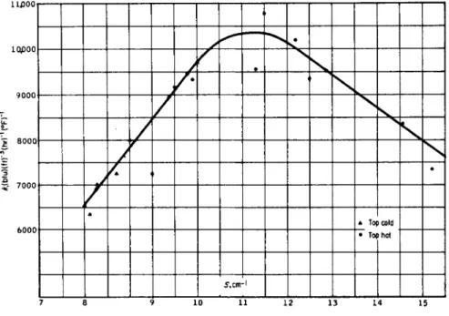
Figure 4 . 1 4 is a plot of the volumetric heat transfer coefficient, k vs.
S. It appears that the heat-transfer coefficient increases as specific surface increases and reaches a maximum of about 1 0 , 5 0 0 when S ~ 1 1 . 5 c m- 1, after which it decreases as S increases. A plausible explanation is that as drop size decreases or holdup increases the resistance to water flow between the oil drops increases rapidly.
11J300
10j000|
9 0 0 0
5 800Q
6000
•
f • •
ffc •
* Tof >cold )hot
• Tof
>cold )hot
5 , cm • 1
7 8 9 1 0 1 1 1 2 1 3 14 15 F I G . 4 . 1 4 . Effect of specific surface on heat-transfer coefficient.
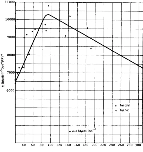
Figure 4.15 is a plot of k vs. Apjh and it appears that k reaches a maxi
mum of about 10,300 when Apjh ~ 95 dynes/cm3. Water flows downward because it is heavier than oil. The driving force expressed as pressure
11000
10000
9000
8000
6000
•
•
• •
•
• •
•
•
Δ Τ op cold op hot
• Τ op cold op hot
(dyne* >)(cmf 3
δ p/h (dyne* >)(cmf 3
40 60 80 100 120 140 160 180 200 220 240 260 280 300
1
F I G . 4 . 1 5 . Effect of Apjh on heat-transfer coefficient.
is Apg or about 2 0 0 dynes/cm2/cm of length. T o calculate Ap it has been necessary to make several assumptions, so it is not surprising to find a maximum at 95 instead of 200. T o the right of the maximum the column is inoperable unless the water channels, or the drops, or both, coalesce.
Actually column operation is affected by so many variables that it has not been possible to define optimum conditions. Only volumetric heat- transfer coefficients have been calculated. These have varied from
4 0 0 0 to almost 11,000 (Btu)(ft)-8(hr)-1(°F)-1, refering to column volume.
The water flow rate, expressed as superficial mass velocity, has varied from 2000 to 5500 (lbXftJ-^hr)-1.
T A B L E 4 . 6
EFFECT OF SPECIFIC SURFACE ON H E A T - T R A N S F E R COEFFICIENT
D,b S* Ap/h,
No. ( B t u K f t J - ' i h r ) -1^ ) -1 cm c m- 1 dynes/cm3 T o p hot, mean water temperature 1 4 6 ° F
1 7 2 4 0 0 . 3 0 2 0 . 4 8 9 . 5 2 9
2 8 9 5 0 0 . 3 2 0 0 . 5 3 9 . 9 3 9
3 9 1 2 0 0 . 3 3 6 0 . 5 6 1 0 . 0 4 6
4 9 3 3 0 0 . 3 3 3 0 . 5 8 1 0 . 4 5 9
5 9 4 4 0 0 . 3 5 6 0 . 6 1 1 0 . 3 6 4
6 9 7 1 0 0 . 3 7 1 0 . 6 5 1 0 . 5 8 7
T o p cold, mean water temperature 1 4 4 ° F
7 6 3 8 0 0 . 3 4 2 0 . 4 6 8 . 1 1 9
8 6 5 3 0 0 . 3 6 1 0 . 4 8 8 . 0 1 9
9 6 9 2 0 0 . 3 7 7 0 . 5 2 8 . 3 2 5
1 0 7 0 0 0 0 . 3 7 4 0 . 5 2 8 . 3 2 6
1 1 7 2 4 0 0 . 3 9 9 0 . 5 8 8 . 7 3 8
1 2 7 9 9 0 0 . 4 1 4 0 . 6 2 9 . 0 5 1
T o p hot, mean water temperature 1 8 7 ° F
1 3 9 3 4 0 0 . 2 8 1 0 . 6 1 1 3 . 0 8 9
1 4 1 0 7 8 0 0 . 3 2 0 0 . 6 4 1 2 . 0 9 5
1 5 9 0 7 0 0 . 2 9 6 0 . 5 8 1 1 . 8 1 3 3
1 6 1 0 2 0 0 0 . 3 1 6 0 . 6 7 1 2 . 7 1 4 3
1 7 9 5 3 0 0 . 3 0 5 0 . 6 8 1 3 . 4 1 8 3
1 8 8 3 6 0 0 . 2 6 2 0 . 6 6 1 5 . 1 1 9 1
1 9 7 3 4 0 0 . 2 6 3 0 . 6 9 1 5 . 7 3 0 5
° ky heat-transfer coefficient.
b Dy average diameter of oil drops.
c Hy holdup.
d Sy specific surface.
J . OPERATING DIFFICULTIES
(1) W h e n the mass flow rates of water and oil are too low, the oil drops coalesce at the top faster than they are formed at the bottom of the column, the packing decays, and heat-transfer coefficients are greatly reduced. Based on present knowledge, 2000 (lb)(ft)~2(hr)_1 is about the minimum acceptable flow rate. The upper limit of flow rate has not been defined, but as the rate increases, the holdup of oil and heat
transfer decreases. T h e acceptable maximum is probably about 6000 (lb)(ft)-2(hr)-i.
(2) Columns having a height of 9 ft have been operated with no visible increase in drop size between bottom and top. Columns 17 ft high have always shown some increase in drop size. The mechanism of coalescence is not understood fully, but based on present knowledge column height must be limited to about 10 ft.
(3) T h e sea-water column is necessarily hotter at the bottom than at the top. Under some circumstances, convection currents can cause mixing and greatly reduce the heat-transfer coefficient. Conditions for stable operation have not been completely defined but depend on both column length and temperature difference top to bottom (Atw). Based on present knowledge, 4 0 ° F is about the maximum temperature difference for stable operation of a 10-ft column.
(4) Under some conditions, a few very small oil drops may be entrained in the exit-water stream. Complete separation has always been obtained by passing the water stream through a centrifugal separator (wet cyclone). This procedure causes a small additional pressure drop.
If the above limitations are accepted, a reasonable value for k is 8000, but it must be remembered that two columns are involved. Assuming that they have equal volume and equal coefficients, the over-all coefficient will be 8000/4 = 2 0 0 0 ( B t u ) ( f t ) -3( h r ) -1( ° F ) -1.
K . HEAT-EXCHANGER SYSTEMS FOR
LARGE S E A - W A T E R CONVERSION PLANTS
T h e data presented above may be used to design a heat-exchanger system for the case previously considered (Fig. 4.3).
Basis 1 lb sea water feed per hour:
Atw (sea water) = (291 - 55) = 236°F, Atw (fresh water) = (295 — 59) = 236°F. Assume six 10-ft sections in each column. Total height 6 0 ft, Atw = 39.3° per section. Assume k = 8000 (Btu)(ft)-3 ( h r )- 1( ° F )- 1 for each column. Required approach temperature 2°F.
(236)/(2)(8 Χ 103) = 0.01475 ft3 volume required. (0.01475)/(60) = 2.458 X 1 0 "4f t2 area required. Gw = 1/2.458 X 10~4 = 4068 (lb) (ft)-«(hr)-i.
Note that h, Atw , and Gw are within the limitations specified. Due to the change in specific heat of oil, the heat-transfer coefficient calculated from end temperatures will be 1.08 times the true coefficient. T o attain
the desired approach temperature, area must be increased 8 % and Gw
decreased 8 % .
(2.458 x 10⁻⁴)(1.08) = 2.655 Χ 1 0 "4 ft2 area required. (4068)(1.08) - 3767 ( l b X f t J - ^ h r ) -1.
Basis 1000 gal/day product:
21.9 ft3 volume required for each column. 0.365 ft2 area required for each column. A plant producing 1 06 gal/day would require two cylindrical columns each 2 1 . 5 ft in diameter and 60 ft high. A plant producing 1 07 gal/day would require two cylindrical columns 63 ft in diameter.
L . ENERGY REQUIRED TO CIRCULATE O I L AND WATER IN HEAT EXCHANGERS
Referring again to Fig. 12, which is based on a frictionless system, each pound of water flowing suffers a head loss of 0.14A ft. Each pound of oil flowing suffers a head loss of 0.075 ft, equivalent to 0.06 ft of water.
Since the mass of oil flowing is approximately 1.86 times the mass of water flowing, the total energy required is [(0.14) -f (0.06)(1.86)]A = 0.252A ft-lb/lb water flowing. If there are two columns each 60 ft high, the total energy required is
i ? ) ^ g M = 120 ft-lb/lb of product.
This is equivalent to 0.375 kw-hr/1000 gal of product, because the ratio (product)/(total water flow through heat exchanger) equals 0.253.
Actually, a simple column is almost frictionless. (Head loss through the oil-dispersion plate is ~ 0 . 1 ft of water). W h e n the column is section
alized, additional power will be required to overcome loss of velocity head, friction in the connecting pipes, and back pressure imposed by control devices. Probably the best solution is to stack the sections as illustrated in Fig. 4.16.
By properly adjusting absolute pressures, only three pumps are needed (one each for fresh water, salt water, and oil). Such a system has not been operated, but a reasonable estimate of energy required is less than 1 kw-hr/1000 gal of product. Additional information on experimental heat exchangers may be found in the studies by the Fluor Corporation (1962), the F M C Corporation (1963), and Woodward (1961).
Inert gas at controlled
pressure
Oil-dispersion plate Δ , ~ 0 . 1 Oil-water interface
4.0 ft Steel plate
Variable restriction Level control h*— Oil-gas interface
Plastic grid Water distributor
Δ ^ ^ Ο . 2
F I G . 4 . 1 6 . M e t h o d of stacking heat-exchanger sections.
IV. Economics of the Vapor Reheat Process
A. GENERAL
As the first vapor reheat plant is still in the experimental design stage, precise estimates of capital and operating costs are impossible, but some approximations may be useful.
In most distillation plants, sulfuric acid is added to sea water to convert bicarbonate into C 02 , which is then removed in the deaerator.
Feed to the evaporators is maintained at a pH of about 7.5, to prevent scale formation. Sea water having a pH of less than about 9 is quite corrosive to concrete. In the vapor reheat process, scaling presents only a minor problem, and it is proposed to remove C 02 by adding lime and converting bicarbonate into carbonate, which precipitates as C a C 03 . This method is used by several plants that produce M g O from sea water.
The treated sea water has a pH of 10 to 10.5 and is not corrossive to concrete, at least not at ambient temperatures. Concrete tanks which have contained alkaline sea water for 2 0 years are still in excellent condition.
Another advantage of lime treatment is that the precipitated calcium
carbonate removes other suspended solids and any organic material (plankton) that may be present. Some concern has been expressed that organic matter in sea water might contaminate the hydrocarbon heat- exchange liquid. Although extensive tests at high temperatures have not been made, it is the opinion of some experts that prestressed concrete can be used for heat-exchange columns and evaporator shells. The cost of large vessels with a working pressure of 100 psig has been estimated at
$2.00/ft3 (Lyn, Τ . Y., 1957).
B. FLASH CHAMBERS AND CONDENSERS
The open channels used for condensers can be made from inexpensive materials, possibly plastics, for the low-temperature stages. They are subject to very little stress. A cost of $0.50/ft2 channel area installed will be used for estimating purposes. For each 1000 gal/day installed capacity, 30 ft3 of flash chamber1 and 106 ft2 of condenser will be assumed.
($2.00)(30) + ($0.50)(106) = $ 1 1 3 . If we refer the combined flash chamber and condenser investment to condenser surface only, we have
$113/106 = $1.07/ft2 of condensing surface.
C. HEAT EXCHANGERS
L Shells
If heat-exchanger sections are stacked as suggested (Fig. 4.16), they must be separated by an estimated 4 ft. This adds 4 0 % to the cost of the column.
2. Oil-Dispersion Plates
Ceramic is probably the best material for oil-dispersion plates. It is hydrophylic, noncorrosive, and practically indestructible. Plates might be cast or "drilled" by a hydrofluoric acid etching process developed by Corning. One manufacturer has suggested a price of $10/ft2 (in quantity).
The cost of plate holders, water distribution system, and connecting pipes has been estimated at $7/ft2.
Although oil holdup in the column is only about 70 % , an additional quantity will be needed to fill connecting pipes and collecting areas. A n inventory which will fill the entire column appears to be ample. Cost is estimated on the basis of a recent quotation, but it is expected to be less in quantity.
1 Size of flash chambers in original Point L o m a Plant of the Office of Saline Water, U . S . Department of the Interior.
A n oil storage tank large enough to contain all the oil must be provided.
Estimated cost, $0.25 ft3. Approximate cost of heat exchangers for each 1000 gal/day production is then:
Shells (21.9)(2)(1.4)($2.00) $123 Dispersion plates (0.365)(2)($10.00)(6) 44 Plate holders, water distributors, and
piping (0.365)(2)($7.00)(6) 31 Oil(21.9)(2)(1.4)($1.37) 84 Oil storage (21.9)(2)(1.4)(0.25) 15
Total $297
$297/43.8 = $6.78/ft3 of effective heat-transfer volume.
D . C O S T COMPARISON OF V A P O R REHEAT AND MULTISTAGE FLASH
The Bechtel Corporation (1963) has recently made a study of large-size saline-water conversion plants using the flash distillation method. Their
T A B L E 4.7
C O S T D A T A FOR 1 4 χ 1 0β GAL/DAY F L A S H D I S T I L L A T I O N PLANT**
Amortization6 (includes taxes and insurance) 9 . 4 % per a n n u m Operating days per year 3 3 0 Amortized capital cost per day = (capital cost)(2.8$ X 10~4)
Amortized capital cost per hour = (capital cost)(1.187 X 10~5) Cost of steam
Fuel 400/10° Btu Amortization (boilers & accessories) 30/1O6 Btu
Total 4 3 0 / 1 0e Btu = 0.150/kw-hr Cost of pumping with steam turbines
Amortization 0.1360/kw-hr Steam ( 5 0 % efficiency) 0.3000/kw-hr
Total 0.4360/kw-hr Capital cost of heat-transfer surfaces (includes tubes and flash chamber)
$3.18/ft2
Heat-transfer coefficient flashing brine to tube side brine. Based on log mean At. Corrected for boiling-point elevation
4 0 0 Btu/ft2/hr/°F
a Bechtel Corporation ( 1 9 6 3 ) .
b Amortized cost includes taxes and insurance. It is designated C*_ by T r i b u s and Evans ( 1 9 6 2 ) . See Chapter 2.