Global Reactor Calculations
Makai Mihály & Dániel Péter Kis
2014. február 3.
The present work discusses a segment of the calculational model of reactor calculation, the so called global reactor calculation. The design, the surveillance, safety analysis, the control, and the economic operation is based on models of the nuclear reactor. The models are complex, they require a large amount of input data ranging from the fine details of the geometry to the detailed isotope compositions of the various reactor materials. The input data feed a physical model describing the neutron population in the reactor core. Unfortu- nately the equations of reactor physics have only numerical solutions in the applications, so the reactor models are computer programs.
The global reactor calculation is the last element of a computation chain which starts with the processing of nuclear data library and continues with the fuel cell calculations, the fuel assembly calculation. All the above mentioned elements contribute to the success or failure of the global calculation.
The present work focuses on the physical and mathematical models of the reactor calcula- tion. The mathematical models determine the problem to be solved, in details the equation, the boundary condition, the numerical procedure used to determine the solution. A prac- tical problem, like the assessment of safety, requires the solution of several mathematical problems. Those working in the nuclear industry, or for a nuclear safety authority, should understand the nature and limit of the involved models.
The Reader is assumed to be familiar with the operation of a nuclear reactor. The treatise focuses on the following topics:
1. The physical and mathematical models used in the global reactor calculation.
2. Provision of input data for the global reactor calculation.
3. The diffusion equation is the corner stone hence we discuss the diffusion theory in details through four Chapters.
4. The numerical methods used to solve the fundamental equations i.e. the Boltzmann equation and the diffusion equation are only mentioned shortly.
5. The iteration process deals with some general problems of large linear equation systems.
6. Immediate applications of the global reactor calculations in the evaluation of in-core measurement processing, in the reactor control and operation as well as in assessing safety issues are dealt with separately.
7. Additional operational questions, like fuel cycle optimization, stability problems, ma- nagement of transient processes are mentioned only in short.
The material assumes the Reader to be familiar with the basic techniques of linear al- gebra and matrices, probability theory and statistics, as well as basics of functional analysis.
The fission process, the neutron-nucleus interaction, the cross-section of a nuclear reaction is assumed to be known from former nuclear physics studies. Some topics of the applied ma- thematical tools are summarized in the Appendices. Section 2. is based on the contribution provided by János Végh (Centre of Energy Research, Hungarian Academy of Sciences)
Tartalomjegyzék
Foreword 1
Contents 7
1. What is a Nuclear Reactor? 8
2. Nuclear Reactors 11
2.1. Nuclear reactors for electricity production . . . 11
2.1.1. Fundamentals of nuclear energy production . . . 11
2.2. Nuclear power plant types and generations . . . 18
2.2.1. Generation I - prototype and demonstration reactors . . . 18
2.2.2. Generation II - the power reactors operated today . . . 19
2.2.3. Generation III - the reactors available for construction today . . . 19
2.2.4. Generation IV - the reactors of the future . . . 20
2.3. Technology of nuclear power stations with PWR technology . . . 21
2.3.1. Primary circuit . . . 22
2.3.2. Secondary circuit . . . 23
2.4. Safety philosophy - defense in depth principle for Generation III plants . . . . 23
2.4.1. Application of defense in depth for new reactor designs . . . 23
2.4.2. Special safety design features of Generation III reactors . . . 25
2.5. Problems . . . 29
3. On Reactor models 30 3.1. Control theory models . . . 30
3.1.1. A simple system theoretic model of a reactor . . . 31
3.1.2. Control theory model . . . 32
3.2. Physical model . . . 35
3.3. Realistic reactor models . . . 35
3.4. Nuclear physics of fission . . . 36
3.4.1. Nuclear Properties . . . 36
3.4.2. Nuclear reactions . . . 42
3.5. The physical background of chain reaction . . . 51
3.5.1. The mathematical problem . . . 58
3.5.2. Boundary conditions . . . 59
3.5.3. Reactor control . . . 64
3.6. Alternative formulations . . . 65
3.6.1. Integral transport equation . . . 65
3.6.2. Adjoint transport equation . . . 66
3.6.3. Formal inverse . . . 73
3.6.4. Variational formulation . . . 74
3.7. Response matrices . . . 75
3.8. Input data . . . 81
3.9. Creation of input data . . . 82
3.10. Validation and verification . . . 82
3.11. Problems . . . 83
4. Providing Input 85 4.1. Energy condensation . . . 86
4.2. Homogenization, asymptotic theory . . . 89
4.2.1. Asymptotic analysis . . . 90
4.2.2. Finite lattice . . . 94
4.2.3. Heterogeneous lattices . . . 96
4.2.4. Homogenization methods . . . 99
4.3. Simplified boundary condition . . . 101
4.3.1. Simplifications . . . 101
4.4. Problems . . . 102
5. Neutron spectrum 104 5.1. Fast neutrons . . . 105
5.2. Slowing down . . . 106
5.2.1. Placzek transients . . . 111
5.2.2. Slowing down in the general case . . . 114
5.3. Resonance region . . . 118
5.3.1. The subgroup method . . . 120
5.3.2. Resonance integral . . . 124
5.3.3. Resonance absorption in a lattice . . . 126
5.3.4. The Doppler effect . . . 129
5.4. Thermalization . . . 130
5.5. Fermi age . . . 135
5.6. Validation and verification . . . 136
5.7. Problems . . . 137
6. Diffusion Equation 138 6.1. Derivation of the diffusion equation . . . 139
6.2. Mathematical properties of the diffusion equation . . . 141
6.3. Derivation and limitations . . . 147
6.4. One group diffusion theory . . . 148
6.5. Few group diffusion theory . . . 153
6.6. RMs in diffusion theory . . . 156
6.7. Time dependence in diffusion theory . . . 161
6.8. Problems . . . 163
7. Solution Methods 165 7.1. Kinetics . . . 166
7.2. Reactor kinetics . . . 169
7.3. Approximate solution of the time dependent diffusion equation . . . 172
7.4. Reactivity measurement . . . 174
7.5. Control rod characteristics . . . 175
7.6. Deterministic reactivity measurement . . . 176
7.7. Problems . . . 178
8. Numerical Methods 179 8.1. Acceleration . . . 184
8.2. Finite difference . . . 186
8.3. Finite elements . . . 187
8.4. Nodal methods . . . 191
8.4.1. Nodal diffusion theory . . . 192
8.4.2. Nodal transport theory . . . 193
8.5. Pn method . . . 203
8.5.1. Spherical harmonics . . . 203
8.5.2. ThePn equations . . . 205
8.6. Sn method . . . 209
8.6.1. Directions and weights . . . 210
8.6.2. Boundary conditions . . . 212
8.6.3. FD and nodal schemes . . . 215
8.6.4. The ray effect . . . 218
8.7. Collision probability method . . . 218
8.8. Problems . . . 220
9. Model Making 222 9.1. Cell calculation . . . 223
9.2. Assembly calculation . . . 226
9.3. Full core calculation . . . 226
9.4. Burnup calculations . . . 228
9.4.1. Fuel chains . . . 229
9.4.2. Xenon poisoning . . . 231
9.4.3. Samarium poisoning . . . 233
9.4.4. General treatment . . . 234
9.5. Problems . . . 235
10.Global Calculation and In-Core Measurements 237 10.1. The goal of core surveillance . . . 238
10.2. Measured fields . . . 239
10.3. Measurement techniques . . . 244
10.3.1. Temperature measurement . . . 245
10.3.2. Flux or power measurement . . . 246
10.4. Core monitoring . . . 247
10.4.1. Determination ofTmax-assembly level . . . 247
10.4.2. Determination ofTmax -subchannel . . . 251
10.4.3. Determination ofWmax . . . 254
10.5. Measurement and safety . . . 255
10.6. Problems . . . 257
11.Appendix A: Mathematical Basics 261
12.Appendix B: Basic Thermal Hydraulics Codes 267 13.Appendix C: Kolmogorov Forward and Backward Equation, Pál–Bell equa-
tion 269
Ábrák jegyzéke
1.1. Fission process (source: Encyclopedia of Science, internet) . . . 9
2.1. Operating scheme of the two most widely used light-water cooled reactor type [8] . . . 13
2.2. The general scheme of the nuclear fuel cycle ([9]) . . . 14
2.3. Main steps in the nuclear fuel fabrication process . . . 17
2.4. The four generation of nuclear power reactors . . . 18
2.5. Operation scheme of a pressurized water reactor ([13]-[20]) . . . 21
2.6. Comparison of selected features of currently operating reactors with the fea- tures of EPR ([14]) . . . 26
2.7. Scheme of the EPR "core catcher" ([14]) . . . 27
2.8. Cooling of the external surface of the vessel by flooding the reactor cavity ([16]) 28 3.1. Attractor . . . 33
3.2. Limit Cycle . . . 33
3.3. The nuclear binding energy per nucleon . . . 38
3.4. The neutron induced fission process . . . 51
3.5. The distribution of fragments for neutron induced fission process . . . 52
3.6. Fourier transforms at the boundary of a square . . . 79
3.7. Fourier transforms along half-boundaries of a square . . . 80
3.8. Fourier transforms at the boundary of a square . . . 81
4.1. Core Reflector Boundary (PWR) . . . 102
5.1. Slowing down by elastic collisions in LCS and CMS . . . 108
5.2. Energy dependence ofω`, `= 1, . . . ,4 of deuterium . . . 110
5.3. Placzek transients for four nuclei . . . 114
5.4. Energy dependence of the flux and the total cross-section . . . 119
6.1. The fundamental mode (blue line) and the transient (red) . . . 156
7.1. Theρ(ω)curve . . . 174
8.1. Coordinates in a triangular element . . . 190
8.2. Coordinates where the solution is determined in a triangular element . . . 190
8.3. Cell and face numbering in the square lattice . . . 202
8.4. Discrete directions in theSN method . . . 216
10.1. Radial flux in the fast group . . . 241
10.2. A PWR core . . . 243
10.3. Principle of thermocouple (source:Wikipedia) . . . 245
10.4. Rhodium detector decay scheme . . . 246
10.5. SPND detector string . . . 258
10.6. Thermal hydraulics analysis of an assembly (source: IAEA web site) . . . 259
10.7. Interrelationship between a safety limit, a safety system setting and an ope- rational limit. . . 260
Táblázatok jegyzéke
1.1. Distribution of fission energy . . . 10
2.1. Defense in depth concept . . . 24
2.2. Additional defense in depth levels . . . 24
3.1. Characteristics of the neutron distributions . . . 57
5.1. Moderating properties of some nuclei . . . 110
6.1. Symmetry components of partial current moments . . . 158
7.1. Delayed neutron group decay constantsλi and abundancesai . . . 167
7.2. Doubling time vs. reactivity . . . 174
8.1. Angular flux and boundary net currents in cell No. i . . . 202
1. fejezet
What is a Nuclear Reactor?
The subject of the present work is the nuclear reactor in which a part of the binding energy of a fissionable nucleus is released in a process called fission. The energy release is accompanied by radioactive radiations. The binding energy is 107 times larger than the energy released in chemical reactions therefore the power density in a nuclear reactor is also larger than in the traditional power plants.
Nuclear reactors are classified by their usage as
• energy production;
• propulsion;
• heat source;
• hydrogen production;
• transmutation;
• research;
• education and training.
Energy production takes place in a nuclear power plant, nuclear propulsion is used in ships.
Nuclear reactor appears as heat source in district heating plants. Immediate hydrogen pro- duction is a recently developing application. The transmutation is a research topic aiming at reducing the storage time of high activity nuclear waste. A nuclear reactor is used as a neutron source in the structure research of complex biological materials, or, in the research of the catalysis. Reactors small in size and low in power are used in education and training.
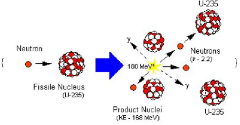
The heart of the nuclear reactor is the fission process. Some nuclei absorb a neutron and the excitation caused by the binding energy of the absorbed neutron suffices to excite the newly formed nucleus so that it splits into fragments. The process is shown in Fig. 1.1.
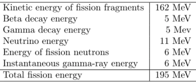
Some of the fissionable nuclei emit also one or more neutrons. That led Leo Szilárd to the idea that self-sustaining fission, the so called chain reaction, can be established. The fission of 235U shown in Fig. 1.1, results in two fragments of more or less equal mass, and two- or three neutrons. To obtain self-sustaining fission, one needs to arrange the material in such a structure that allows for the neutrons to hit another235U nucleus before being absorbed by another nucleus. The distribution of the energy released in fission is shown in Table 1.1.
1.1. ábra. Fission process (source: Encyclopedia of Science, internet)
Kinetic energy of fission fragments 162 MeV
Beta decay energy 5 MeV
Gamma decay energy 5 Mev
Neutrino energy 11 MeV
Energy of fission neutrons 6 MeV Instantaneous gamma-ray energy 6 MeV
Total fission energy 195 MeV
1.1. táblázat. Distribution of fission energy
We see from the table that majority of the energy appears as kinetic energy, i.e. as heat.
In order to produce energy, we have to achieve not only the self sustaining fission but also removing the generated heat. In addition, the power released from fission should be kept at a constant level, thus the energy production is also a regulation problem.
The next Chapter gives an overview of nuclear reactors.
2. fejezet
Nuclear Reactors
2.1. Nuclear reactors for electricity production
2.1.1. Fundamentals of nuclear energy production
In this chapter a general overview of the technology applied for energy production in nuclear power stations is outlined, starting with processes taking place in the active core, continuing with heat exchange in the steam generator and ending with the generator supplying electricity to the grid. Description of the various phases of the nuclear fuel cycle is also given, detailing the history of the uranium ore from the mine to the final spent fuel storage, as well as discussing differences between UO2 and MOX fuel. The purpose is to illustrate the main steps in the technology of nuclear electricity production, therefore other type of plants (e.g.
for provision of process heat) are not treated here.
Basic principles
The basic process utilized for energy production in any nuclear power station is the controlled and self-sustaining chain reaction of fissile nuclei. The heat generated in the chain reaction is removed by an appropriate coolant material and after suitable conversion the thermal energy is used for producing electricity. The nuclear fuel resides in the so called active core, the fuel consists of fissile isotopes, as well as fertile isotopes that can produce fissile isotopes through nuclear reactions. Generally the fissile material in the fuel is constituted by uranium or by an uranium-plutonium mixture (the latter is called MOX fuel). In nature there exists only one isotope, namely 235U, which undergoes fission induced by low energy (thermal) neutrons, but unfortunately this isotope constitutes only 0,72% of natural uranium. The vast majority (99,275%) of natural uranium is constituted by the 238U isotope: high energy (fast) neutrons induce fission in it, but a self-sustaining chain reaction cannot be maintained in an active core constructed solely from238U isotope. In the industrial practice the following fissile isotopes are utilized most commonly: 235U, 239Pu,241Pu and 233U. In nature there exist two important fertile isotopes, 238U and 232Th. The first one produces 239Pu after a neutron-capture event, while the thorium isotope produces 233U. The 241Pu isotope is produced when the240Pu artificial (i.e. not existing in the nature) fertile isotope undergoes a neutron-capture event. The isotope 240Pu is created by a similar process from239Pu (see [6] and [7] for details).
Heat is produced by various processes in the active core of a reactor:
• High energy fission products slowdown in the fuel, in the structural materials and in the coolant, and during this process the kinetic energy of the fission products is transformed to heat (thermal energy).
• The gamma radiation produced during the fission process is absorbed and its energy is transformed to heat.
• Heat is also produced by the radioactive decay of the fission products.
The released energy is very large: the energy released during the fission of a single gram of235U is equivalent to the energy released by burning 3 metric tons of high quality coal.
Reactors commonly operated in nuclear power stations can be classified according to various principles. One possible approach is the classification according to the energy of the neutrons inducing fission in the reactor:
• The chain reaction in the "thermal reactors" is maintained by low energy neutrons, slowed down to the thermal energy region. The vast majority of the energy producing reactors of today belongs to this class. In order to slow down the high energy neutrons produced in the fission process, these reactor types use a so called moderator material (mainly light water or heavy water or graphite is applied as moderator). Thermal neutrons have a very advantageous feature: when fissile isotopes (e.g. 235U or239Pu) are bombarded by thermal neutrons, these isotopes undergo induced fission with much higher probability compared to the case of fast neutrons. This circumstance makes it possible to use low (<5%) enriched uranium, or even natural uranium as fuel material.
• The chain reaction in the so called "fast reactors" is maintained by high energy neutrons without slowing down, as produced in the fission process. These reactor types do not use moderator and the coolant must not slow down the neutrons either (special coolant applicable in fast reactors is the liquid sodium, for example). Fast reactors use higher fuel enrichment (figures around 20% are typical) in order to compensate the high neutron capture effect (i.e. neutron absorption) of the238U isotope.
Another commonly used method is to classify according to the material of the moderator used to slow down the neutrons. Generally the following classes are defined:
• Light-water (H2O) moderated reactors (this is the most widely used type, and generally these reactors use light-water as a coolant, as well), see Fig 2.1.
• Heavy-water (D2O) moderated reactors (e.g. CANDU, developed by AECL, Canada).
• Graphite moderated reactors (e.g. Advanced Gas Cooled Reactor, AGR).
• Light element (lithium or beryllium) moderated reactors (e.g. Molten Salt Reactor).
Another classification method distinguishes between the reactor types according to the coolant material used for core cooling. According to this method the following types are defined:
• Light-water cooled reactors have two basic types, the pressurized water and the boiling water reactors, Figure 2.1. illustrates the operating scheme of these two types. The water in a pressurized reactor is kept at sufficiently high pressure, to prevent boiling even at the high operation temperature. The coolant flows through the core, then it is led into a large heat exchanger called steam generator, where the coolant looses a considerable fraction of its energy and produces steam. The steam is led to a steam
2.1. ábra. Operating scheme of the two most widely used light-water cooled reactor type [8]
turbine and the turbine drives a generator producing electricity. There are no steam generators in a boiling water reactor, because the coolant reaches the boiling state within the active core and this steam is led directly to the turbine.
• In gas cooled reactors the heat is removed from the core by an inert gas, e.g. helium or carbon dioxide. The cooling gas either directly drives a special turbine, or the gas is used for producing steam in a steam generator and the steam is led to a conventional steam turbine.
• Liquid metal (sodium or lead) coolants are used in fast reactors, because these materials are good coolants, but bad moderators, i.e. they do not slow neutrons down.
• Molten salt is used as coolant medium in molten salt reactors (MSR), generally lithium or beryllium salts formed with fluoride are applicable for industrial purposes.
It is also common to define "reactor generations" according to the time interval when reactors were developed and constructed. Reactor generations are treated in 2.2 in detail.
Nuclear fuel cycle
Figure 2.2 shows the history of the uranium ore from the mine to the storage place of radioactive waste or to the fuel reprocessing facility. The history of uranium from the uranium mine to the final spent fuel storage facility or to the reprocessing factory is a long, multi-step process, containing complex chemical, mechanical and other industrial engineering operations. This process is generally called nuclear fuel cycle. Two fuel cycle types are distinguished, depending on what happens with the spent fuel removed from the nuclear power station after the fuel utilization is over. In the so called "open" fuel cycle the fuel is not reprocessed, but after a sufficiently long storage period it is placed in a storage place specially designed and constructed for the safe storage of highly radioactive spent fuel elements. The vast majority of the present nuclear power stations uses this open fuel cycle approach, despite the fact that there is no final spent fuel storage facility in any country yet (design and construction works are going on in several countries). In the so called "closed" fuel cycle the spent fuel is reprocessed in a special factory. During reprocessing plutonium and uranium is extracted from the fuel by using chemical methods, later these materials are used to fabricate new fuel elements. The result is the MOX fuel, see Figure 2.2. In the "closed" cycle the highly radioactive waste - remaining after reprocessing - must be stored at a suitable final repository. In the following Subsections a short description of the "open" fuel cycle is given.
2.2. ábra. The general scheme of the nuclear fuel cycle ([9])
Uranium mining
As of today, the mining of uranium ore is carried out by using three different methods.
Open-pit mines are set up at those places where the uranium ore is abundant in layers close to the surface of the Earth. Deep pit mines are constructed at those places where the layers rich in uranium ore are located deep (sometimes several hundred meters) below the surface. Recently the application of a novel method is spreading: the basic principle of this
"in situ leaching" method is that a liquid substance containing acidic or alkaline chemicals is being pumped below the surface, into the rock layer containing the uranium ore. The liquid - among others - dissolves the minerals containing uranium, then this liquid (containing dissolved uranium ore) is taken back to the surface where it is further processed to extract uranium. The waste liquid substance remaining after the processing is pumped back, under the surface of the soil. This method does not cause "landscape wounds" as open pit mines do not produce the large amount of waste rock, a well-known characteristics of deep pit mines. In the first phase of processing the uranium ore obtained from the mine is taken through the usual ore processing steps: it is milled into small pieces in an ore mill, then it is selected, cleaned and dried. At the end of this process a fine powder substance is obtained, it is already suitable to start chemical processing, consisting of the following steps:
• by using a suitable chemical solvent material, the uranium present in the ore-powder is solved into an alkaline, acidic or peroxide solution,
• the uranium solution is then separated from the other components,
• in the last step the uranium is precipitated and the precipitate is dried.
The dried uranium precipitate usually has bright yellowish color, this is why the end-product got its well-known name "yellowcake". The uranium heavy metal content of the yellowcake is at least 70%, but for practical reasons its further processing is carried out inU3O8compound form, containing more than 80% uranium.
Uranium enrichment
The next step in the fuel fabrication process is uranium enrichment. "Enrichment" in this context means "increasing the concentration of the235U isotope in the uranium". However, yellowcake is not an appropriate substance to be used for the enrichment process, so first it is converted to uranium hexafluoride (U F6) gas. This gas can be enriched in two very different processes: one of the methods relies on diffusion, while the other uses centrifuges, but both methods utilize the small mass difference between the235U and the238U isotopes.
In case the U F6 gas diffuses through a porous wall, then the U F6 molecules containing the lighter 235U isotope move faster and on the other side of the wall their concentration will be higher than that of the U F6 molecules containing the more heavy238U isotope. In an industrial application the gas molecules are driven through the porous wall by a high- pressure compressor and the system consists of many diffusion stages. The gas depleted in the 235U isotope is taken back to the previous stages, while the gas enriched in the 235U isotope is forwarded to the next diffusion stages. The parameter called enrichment ratio, characterizing how effectively the enrichment process works, is very small for the gas-diffusion method, therefore approximately 1400 or 1500 diffusion stages are required to achieve the required 4% enrichment (it must be noted that the relative abundance of the 235U isotope is only 0.72% in the natural uranium).
Gas-centrifuges utilize the fact that the centrifugal force acting on a gas molecule with a larger mass is larger compared to a lighter gas molecule. Due to this effectU F6 molecules
containing the more heavy 238U isotopes tend to increase in number at the outer wall of the centrifuge, whileU F6molecules with the lighter235U isotope are more abundant in the region around the middle of the centrifuge. An industrial gas centrifuge is a long vertical cylinder, placed in a closed tank and rotating with very high speed in vacuum. The system is fed byU F6gas and as a result of the fast centrifuging the concentration of the more heavy U F6 molecules is increasing towards the outer wall of the centrifuge. In the long cylinder the flow paths are arranged in such a manner, that the more heavy gas moves towards the bottom of the tank, while the lighter gas moves to the top, allowing a proper separation of the "products" at the bottom and at the top of the centrifuge, respectively. The gas enriched in the 235U isotope is fed to the next centrifugal-stage, while the gas depleted in the 235U isotope is taken back to the beginning of the whole process. At the end of the above described process, 10-15% of the original uranium quantity is obtained as enriched uranium, while 85-90% remains as depleted uranium (note that the 235U concentration in the depleted uranium is much lower than 0.72% characterizing natural uranium). Note that the enrichment ratio of one stage in the centrifugal method is significantly higher than that is for the diffusion method.
Fuel production
After achieving the targeted enrichment (around 4%) fluorine is removed from the U F6 gas, and the remaining powdery enriched uranium is taken to the next phase of the fuel fabrication process. In this phase first ceramic tablets are made from the powder, then fuel rods are constructed from the tablets and several fuel rods are assembled into a so called fuel assembly (see Figure 2.3). Finally these fuel assemblies are loaded into the active core of the reactor of the nuclear power station. The rods are arranged within the fuel assembly in a lattice (grid). Assemblies have lower- and upper rod-fastening structures and coolant flow-guides, as well as several axial spacer grids in order to keep the geometry of the fuel lattice (see Figure 2.3). In the first manufacturing step the uranium powder is pressed to small, cylindrical tablets (these are often called fuel pellets) by using a power metallurgy technology called sintering. Afterwards ceramic pellets are carefully selected according to size and weight, then they are positioned into a long zirconium-alloy tube. Finally the tube is filled with inert gas (helium) and hermetically sealed. This tubular structure constitutes the so called fuel rod. Zirconium is a suitable material, because it does not absorb neutrons, therefore it does not influence the neutron balance of the core. Ceramic pellets themselves retain the solid fission products produced in the chain reaction, and the primary barrier to prevent the emission of gaseous fission products is the cladding of the fuel rod.
As of today, the vast majority of nuclear fuel utilized in the nuclear power stations all over the world is low-enriched (<5%) uranium dioxide used in the form of ceramic pellets.
However, recently some countries (e.g. France, United Kingdom and Japan) gradually star- ted to use a new type of fuel, which is called "mixed oxide" (MOX) fuel. The fraction of MOX is not yet significant in the fuel market, according to the numbers of WANO, in 2009 MOX represented only 2% of the manufactured new fuel. The "mixed oxide" name refers to the fact, that this fuel contains various fissile and fertile isotopes. The most important component of the mixture is plutonium, which is either mixed with natural uranium or with depleted uranium obtained from reprocessing or as a by-product of the enrichment process.
Plutonium is either obtained through spent fuel reprocessing or from the final dismantling of military nuclear warheads (see the "Megatons to Megawatts" Russian-USA program).
It is a general practice to load 33% or 50% MOX fuel into the active core, but some modern reactor designs can operate even with 100% MOX core. Main differences between MOX and U O2fuel characteristics are as follows:
2.3. ábra. Main steps in the nuclear fuel fabrication process
• Due to the higher neutron absorption of plutonium, modifications are necessary in the reactor control system if MOX is used (e.g. more control organs are required).
• The MOX fuel pellet has lower heat conductivity coefficient than the U O2 tablet, therefore it has higher temperature. This must be taken into account when reactor safety and operation limits are determined.
• The MOX fuel rod has higher fission gas release rate then itsU O2counterpart, therefore lower maximum burnup levels are achievable with this type of fuel.
During its utilization period approximately 30% of the plutonium originally present in the MOX fuel is burnt out. In today’s thermal reactors the plutonium is utilized only one time, as reprocessed product. After its energy production period is over, the burnt out MOX fuel is not reprocessed in a second round, rather it is stored as spent fuel.
Utilization and final disposal of nuclear fuel
The fuel assembly represents the basic transport unit of the nuclear fuel, fresh and spent fuel is handled in this form, as well. For example, the length of a VVER-440 fuel assembly is 2.5 m, it contains 126 fuel rods and there are altogether 349 assemblies in the core. Assemblies reside 4 or 5 years in the core, it depends on the type of the fuel and the reactor. During this period, as a result of nuclear reactions, the uranium content of the fuel gradually decreases, this process is called burnup. In order to compensate the effects caused by the burnup the active core is periodically reshuffled (generally reshuffling is performed after 12, 18 or 24 months of continuous operation). During core reshuffling the fuel assemblies with the
2.4. ábra. The four generation of nuclear power reactors
highest burnup are removed from the core and they are replaced by fresh fuel with zero burnup. This reshuffling is called "refuelling", and the time period between two consecutive refuelling outages is usually called "fuel cycle". The removed burnt fuel is stored for some years close to the reactor in a special storage place called spent fuel storage pool. During this storage period the fuel is kept under water and at the end of the storage the heat production of the fuel decreases to a very low level allowing the transfer of the fuel assemblies to a dry storage facility. In the dry storage facility the spent fuel can be kept safely for decades and its further processing depends on the fuel cycle policy of the owner nuclear utility. In case of an open cycle, at the end of the process spent fuel assemblies are shipped to a final storage place, which generally means a deep geological repository. In case of a closed cycle, spent fuel assemblies are shipped to a reprocessing factory where assemblies are dismantled and pellets are removed from the fuel rods. Then pellets are dissolved in a chemical process to extract uranium and plutonium from the tablets, and finally the extracted fissile and fertile isotopes are used to fabricate MOX fuel elements. Reprocessing also produces a significant amount of highly radioactive waste, this is also stored in a final repository, generally in a vitrified form.
2.2. Nuclear power plant types and generations
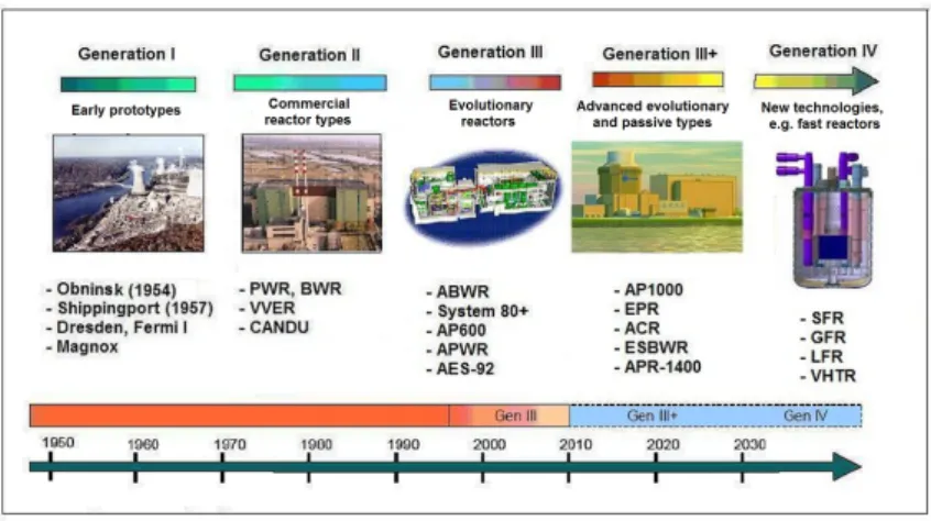
It is common to distinguish four reactor generations in the development process of nuclear power stations (see Figure 2.4).
2.2.1. Generation I - prototype and demonstration reactors
The development history of nuclear power stations can be divided into four distinct periods or generations. Generation I contained small scale prototype or demonstration reactors using various technology: the first unit at Obninsk (Soviet Union, 1954) applied graphite moderator and light-water cooling, the Shippingport unit (USA, 1957) had a light-water cooled, thermal breeder reactor, Dresden 1 (USA, 1960) operated the first commercial boiling water reactor, Fermi 1 (USA, 1957) utilized a fast breeder reactor for energy production, while Magnox reactors (UK, 1956) had graphite moderator and CO2gas cooling. These units were built in
the 1950s and 1960s and most of them are already closed and decommissioned (apart from some old Magnox units still running in the UK).
2.2.2. Generation II - the power reactors operated today
Generation II reactors were designed in the 1970s and 1980s, based on the experience obta- ined with Generation I prototype units. During the intense development work several, more or less standard designs were established. The most important types are the pressurized water reactor (PWR), the boiling water reactor (BWR) and the heavy-water moderated, natural uranium fueled CANDU reactor. Needless to say that the vast majority of the cur- rently operated units belongs to Generation II. If classified according to type, the majority belongs to the PWR or BWR class, but a considerable number of units is operated with the Canadian CANDU technology, as well. In March 2012, all over the World 436 units were operated supplying altogether 370.5 GW net electric power, 68% of the reactors were PWR, 21% were BWR and 11% were other types (see 2.5). It must be noted that the Russian-design VVER units belong to the PWR class.
2.2.3. Generation III - the reactors available for construction today
After the severe accidents at Three Mile Island (1979, USA) and Chernobyl (1986, Soviet Union) significant efforts were concentrated to develop new reactor designs all over the World. The basic aim of the design work was to create reactors having considerably better safety indicators than those valid for Generation II types. Generation III was established in the 1990s, mainly through an evolutionary development process starting from selected Generation II reactors. The most important design target was to reduce the probability of severe accidents, as well as to mitigate the consequences of the severe accidents, if they happened. Recently it is common to mention some advanced Generation III designs as Generation III+ reactors. As a rule these Gen III+ reactors apply more passive safety systems than other Gen III designs, to increase the reliability of the safety systems and to decrease core damage frequency. Passive safety systems are extremely reliable, because they use only "natural" driving forces during their functioning. It means that they are operated by gravity, natural circulation or driven by the energy of compressed gas. Due to their operating principles passive systems do not require emergency power supply, and this feature is a considerable advantage in several aspects. The first Generation III units were put into operation in Japan as early as 1996, these were ABWR (Advanced BWR) reactors designed by General Electric and constructed by Hitachi and Toshiba. Today several Gen III types of later design are available on the World market for construction. The most important currently available ("ready for shipment and construction") reactor types are as follows: EPR (European Pressurized Water Reactor) by Areva, AP1000 (Advanced PWR) by Toshiba-Westinghouse, APR-1400 (Advanced Pressurized Reactor) by KEPCO, large APWR (Advanced PWR) by Mitsubishi, ATMEA1 by Areva and Mitsubishi, MIR-1200 (VVER-1200) by Atomstrojexport. In addition to these PWR types, there are some advanced BWR designs on the market, such as ESBWR (Economic Simplified BWR) and ABWR by General Electric, Hitachi and Toshiba, KERENA by Areva (formerly known as Siedewasser Reactor-1000 by Siemens). Atomic Energy of Canada Ltd. also offers a new, higher power and modernized version of its CANDU design under the name of Advanced CANDU Reactor (ACR).
2.2.4. Generation IV - the reactors of the future
The Gen IV project aimed to develop Generation IV reactors was launched in 2000. The basic aim of the development is to create inherently safe reactor types, surpassing present types in practically all aspects of nuclear safety, economical operation, radioactive waste production, as well as proliferation resistance. It is envisaged that some of the Gen IV reactor types presently in the conceptual design phase will be ready for commercial deployment after 2030.
In the framework of Generation IV project the following reactor types are being developed:
(see [11]):
• sodium cooled fast reactor (SFR)
• gas cooled fast reactor (GFR)
• lead-bismuth cooled fast reactor (LFR)
• high temperature gas cooled thermal reactor (VHTR)
• molten-salt cooled reactor (MSR)
• supercritical pressure, water-cooled reactor (SCWR)
All above listed Gen IV types share ambitious common requirements for safety, reliabi- lity, economical and environment-friendly operation, minimization of radioactive waste, and impossibility to use the technology for military purposes. It is also a common target to operate these reactors in a closed fuel cycle. Considering the present status of the associated R&D work it can be firmly stated that none of these reactors can be commercialized before 2030. In the near future the number of investigated Gen IV types will be decreased and the research work will concentrate on only few (two or three) selected designs to ensure success.
As it was stated earlier, on the present World market only Gen III reactors are available:
Gen II types are not manufactured any more and one must wait for the Gen IV reactors about two additional decades.
In the further treatment only Generation III PWR types will be discussed, because the PWR type gradually became dominant on the market. Reasons for this dominance are manifold. First of all, PWRs have some design features that makes them superior to BWRs.
A PWR unit has three cooling circuits, while a BWR has only two. This technological difference results a considerable difference between the available cooling water inventories, it is mainly due to the large (in certain cases extremely large) water inventory present in PWR steam generators. Larger cooling water masses generally ensure better responses during large transients, i.e. a PWR plant reacts to turbine trips, pipe breaks or even loss of coolant accidents in a more balanced way with larger safety margins during the transient. Another important difference is connected to the reactor pressure vessel (RPV) penetrations: in a BWR control rods are inserted to the core through the bottom of the RPV, while advanced PWR vessels have no penetrations at their bottom part at all. If a core melt accident does happen, in a PWR there are viable means to keep the molten core within the RPV (e.g. by cooling the external wall of the vessel via flooding the reactor cavity by a large amount of water). In a BWR this is not practicable, since the corium will sooner or later pass through the RPV bottom penetrations, and no external cooling can prevent that to happen. An additional fact supporting the PWR type is modern containment technology.
Some Generation III PWRs have an extremely robust double containment, constructed with the latest pre-stressed concrete technology. These containments are so strong that they can withstand the crash of a large commercial airplane without loosing critical safety functions.
2.5. ábra. Operation scheme of a pressurized water reactor ([13]-[20])
BWR type containments generally have smaller volumes than PWR types and the smaller volume allows faster internal pressure build-up.
As it was mentioned earlier, in March 2012 about 68% of the operating reactors belonged to the PWR type. The PWR dominance is even more pronounced if new builds are cons- idered: 63 new units were under construction in March 2012, and 82% of these units were of PWR type. The tendency is quite clear and one may forecast even more PWRs to be built after Fukushima.
2.3. Technology of nuclear power stations with PWR tech- nology
The present Chapter outlines the main features of the PWR technology, it details the main parts of the nuclear steam generation facility and their operating principles, main buildings of the nuclear power station and describes various possible solutions to ensure site specific ultimate heat sink. Basic features of safety principles applied during plant design are also given briefly (e.g. defense in depth, redundancy, diversity, physical separation) in order to illustrate that the risk represented by Generation III reactors is so small that it is close to the reasonably achievable minimum. In the treatment the emphasis is on Generation III PWRs, concentrating on novel technological solutions developed to achieve a high operational safety level, as well as designs to avoid severe accidents and mitigate their consequences.
The operation scheme of an advanced, large PWR nuclear power station is shown in Fig.
2.5. Legend: 1 - pressurizer, 2 - reactor coolant pump, 3 - primary circuit, 4 - reactor, 5 - secondary circuit, 6 - control assemblies, 7 - steam generator, 8 - turbine, 9 - generator + exciter, 10 - condenser, 11 - cooling water (delivers heat to the ultimate heat sink), 12 - feedwater pump.
The heat production unit of the plant is the reactor, in a PWR type plant the heat is transferred from the reactor to the ultimate heat sink by a cooling system consisting of three cooling circuits. The large amount of heat produced in the active core during the nuclear
fission process is removed by demineralized water circulating in a closed cooling loop called primary circuit. The pressure in the primary circuit is kept by the pressurizer at such a value that the water does not boil even at the high nominal temperature (this is the origin of the "pressurized water reactor" name). The primary circuit must be operated with a very high cooling water flow rate, since the core can have a thermal power value more than 4000 MW. The number of primary circulating loops depends on the design, modern Gen III types generally apply 2, 3 or 4 loop arrangements. The heated up primary circuit cooling water transfers energy to another closed cooling loop called secondary circuit. The heat transfer takes place in very large heat exchangers called steam generators and the generated steam is used to drive a steam turbine. Rotation of the turbine produces electric current in the coupled generator by electromagnetic induction. Finally, through switches and transformers the produced electricity is fed into the national electric grid, where generally 400 kV high voltage level is used.
The exhaust steam leaving the low pressure turbine is condensed to water in the conden- ser, using the cooling effect of the ultimate heat sink. The ultimate heat sink can be water (taken from the sea, a lake, or a river) or air, if a cooling tower is used. This tertiary cooling circuit is an open circuit, because the large amount of cooling water taken from the water source is led back to the source, although at somewhat higher temperature. The condensed water is heated up and pumped back to the steam generators by using the feedwater pumps.
In addition to the above described main systems the nuclear steam generating system has various auxiliary systems, as well. These auxiliary systems serve for safety purposes, enhance the performance of the plant or clean the above mentioned three cooling circuits.
In the following subchapters we illustrate the details of the three cooling circuits with data taken from a large PWR.
2.3.1. Primary circuit
The core is housed by a large vertical, cylindrical steel tank called reactor pressure vessel (RPV). The RPV is made of special steel, for the largest reactors its wall can be as thick as 25 cm in the core region and its outer diameter can be more than 500 cm.
The inner surface of the vessel is coated by a special stainless steel called "plating" to ensure anti-corrosion protection. Modern pressure vessels are designed to have at least 60 years service time, this is ensured by using low carbon austenitic steel alloys as vessel material (this material has low radiation embrittlement behavior). The radiation damage of the RPV wall can be further reduced by a special device called heavy reflector: this steel structure surrounds the core and by reflecting the neutrons back to the core region it decreases the fast neutron flux reaching (and damaging) the wall. The integrity of the RPV is enhanced by the fact that there are no penetrations at the bottom of the vessel and there is no vertical welding at all. Cold leg inlet and hot leg outlet nozzles are located in the upper part of the vessel, their number depends on the number of loops and the design of the primary circuit:
there exist designs where there are four cold legs and two hot legs, but in the majority of the reactors the number of hot legs is equal to the number of cold legs. The heat generated in the core is removed by the cooling loops connected to the vessel. The structure of the cooling loops is identical, but one of the loops has an extra equipment called pressurizer, which takes care of the pressure control of the entire primary circuit. When the pressure decreases large heaters are switched on automatically, to keep the pressure at the setpoint (large PWRs operate at 155 or 160 bar nominal pressure). If the primary pressure increases then cold water is injected from one of the cold legs into the pressurizer to lower the pressure according to the setpoint. The circulation of the coolant in the cooling loops is maintained by high-capacity centrifugal pumps called main coolant pumps. The heated up coolant leaves
the pressure vessel through the hot leg nozzles and enters the steam generators. These are large heat exchangers where the heated up primary coolant transfers a large fraction of its energy to the cooling water on the secondary side (this cooling water is called "feedwater").
The cooled down primary coolant is pumped back to the pressure vessel through the cold legs by the main coolant pumps. On the secondary side the feedwater evaporates in the boiling process and the generated steam is led to the steam turbine.
2.3.2. Secondary circuit
The secondary circuit converts the heat produced in the reactor to kinetic and then to electric energy. The feedwater is heated up to boiling by the hot primary water circulating in the steam generator heat exchanger tubes. The steam leaving the steam generator is led to the turbine and rotates the turbine blades by using its kinetic energy. Generation III plants generally have one large turbine, with one high pressure and three low pressure stages and the tendency is to apply "slow" (1500 rpm for 50 Hz grids) machines. In the high pressure stage the steam temperature decreases and its moisture content increases, for this reason a moisture separator and reheater equipment must be applied before the first low pressure stage. This equipment removes water droplets from the steam (these droplets can damage turbine blades) and heats up the steam above the saturation temperature.
2.4. Safety philosophy - defense in depth principle for Generation III plants
The "defense in depth" (often abbreviated as "DiD") principle was already used during the design of the very first nuclear power plants and during the coming decades this principle became a very effective design tool from safety point of view. The proper application of this principle ensures the prevention of various postulated accidents and helps the mitigation of the consequences of severe accidents. Traditionally, when applying the DiD principle, designers tied the postulated accidents and severe accidents to a specific event happened in the technology, called initiating event. Initiating events were selected according to their frequency of occurrence and various DiD levels were defined according to the hypothetical
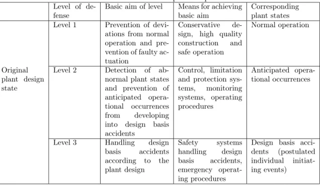
"progression" of the accident: for example if the first level failed then the second level took over, etc. The basic rationale behind this level system was to ensure redundancy, in order to maintain critical safety functions* as long as possible during the escalation of an accident (*critical safety functions are subcriticality, fuel cooling and limiting radioactive releases). The original concept of DiD contained three levels (details can be found in Ref.
[17], [18], [19]): As a further development, in the nineties the so called "beyond design basis accident" (BDBA) category was introduced. Basically those accidents belong to this category, that were not included in the original plant design base, such as accidents resulting as a consequence of multiple failures and severe accidents. In order to handle this new category systematically, two new levels of defense were introduced, see Table 2.2.
2.4.1. Application of defense in depth for new reactor designs
The defense in depth concept proposed for the new reactor designs already contains five levels of defense (see [18] for details):
1. Level 1. The aim is to prevent deviations from normal operation and faulty actua- tions. That goal is achieved by conservative design, high quality construction and safe operation.
2.1. táblázat. Defense in depth concept Level of de-
fense
Basic aim of level Means for achieving basic aim
Corresponding plant states Level 1 Prevention of devi-
ations from normal operation and pre- vention of faulty ac- tuation
Conservative de- sign, high quality construction and safe operation
Normal operation
Original plant design state
Level 2 Detection of ab- normal plant states and prevention of anticipated opera- tional occurrences from developing into design basis accidents
Control, limitation and protection sys- tems, monitoring systems, operating procedures
Anticipated opera- tional occurrences
Level 3 Handling design basis accidents according to the plant design
Safety systems handling design basis accidents, emergency operat- ing procedures
Design basis acci- dents (postulated individual initiat- ing events)
2.2. táblázat. Additional defense in depth levels Level of de-
fense
Basic aim of the level
Means for achieving basic aim
Corresponding plant states Beyond de-
sign basis scenarios
Level 4 Prevention of BDBA si- tuations and mitigation of their conse- quences
Application of ad- ditional measures and devices, and accident manag- ement guides
Multiple failures, severe accidents
Accident mitigation plan
Level 5 Mitigation of radiological consequen- ces in case
of large
radioactive releases
On-site and off-site emergency mitiga- tion measures
2. Level 2. The aim is to detect abnormal plant states and anticipated operational occur- rences from developing into design basis accidents. That goal is achieved by protection systems, monitoring systems, operating procedures.
3. Level 3. The aim is to handle an accident in order to limit radioactive releases and to prevent core damage. The goal is achieved by safety systems and emergency operating procedures.
4. Level 4. The aim is to limit radioactive releases and to prevent core damage. The goal is achieved by safety systems and emergency operating procedures dedicated for handling design base accidents.
5. Level 5.The aim is to mitigate radiological consequences of large radioactive releases.
The goal is achieved by prevention measures in the plant’s vicinity.
As a consequence of the new design philosophy, the design base of the new reactors includes such accidents that are considered as BDBA events for the presently operating plants (such events are for example the accidents resulting from multiple failures). This means, that for the presently operating plants and for the new designs the meaning of the
"beyond design basis accidents" category is different. A further enhancement is the fact that while for the present reactors the DiD deals with the nuclear fuel mainly in those plant states when the fuel resides in the reactor, then for the new designs it includes all possible states of the nuclear fuel (e.g. it includes also those situations when the fuel is stored in the spent fuel storage pool). Characteristic multiple failure cases are, for example:
• anticipated transients without scram (ATWS events),
• station blackout,
• total loss of feedwater,
• small-break LOCA with loss of medium-head safety injection or loss of low-head safety injection system,
• small-break LOCA with loss of component cooling system
• total loss of the spent fuel storage pool cooling system.
The safety analysis of postulated initiating events - combined with the fulfilment of the single failure criterion - can prove the correct functioning of the design solutions applied to ensure proper redundancy. In addition, the analysis of multiple failure scenarios provides information on the fact, whether diverse design solutions applied on the third level of DiD function properly or not.
2.4.2. Special safety design features of Generation III reactors
The most important design features of Generation III reactors are as follows (see e.g. Ref.
[13]):
• There is a strong tendency for equipment standardization, system simplification and more robust manufacturing practice, and for a significant reduction of the number of plant components. This tendency reduces the number of potential failure modes (according to the "simpler is safer" principle) and potentially reduces licensing and construction time.
2.6. ábra. Comparison of selected features of currently operating reactors with the features of EPR ([14])
• Enhanced safety features, achieved mainly by applying passive safety systems. Basic safety design targets defined by nuclear utilities in the European Utility Requirements (EUR) document are fulfilled by these Generation III plants with large margins.
• Basic safety design targets are as follows: CDF (core damage frequency)10−5 /year and LRF (Large Release Frequency)10−6/year.
• The design service time of these units is generally 60 years and the design load factor exceeds 90% (the latter was achieved by enhancing system maintainability and by shortening the time required for refueling).
• The maneuverability of the plants was enhanced significantly, to ensure flexible and safe plant reaction to fast changes in grid load requirements, by controlling the power of the unit and the grid frequency.
• The nuclear fuel was enhanced, as well, resulting in higher fuel burnup levels and more economic fuel utilization. These enhancements result less radioactive waste per unit energy production.
Figure 2.6 shows the comparison of the Generation II reactors currently in operation and the EPR unit:
Generation III reactor design improvements were mainly concentrated on two basic areas:
to avoid hypothetical severe accidents and to mitigate their consequences if they happened.
New designs contain solutions that prevent the dispersion of radioactive materials into the environment even during severe accident scenarios. One frequently used solution is the so called "core catcher" aimed to prevent the melt-through of the concrete located below the reactor pressure vessel during severe accidents with core melt. The core catcher utilizes spe- cial compartments located at the bottom of the reactor cavity in order to spread the molten
2.7. ábra. Scheme of the EPR "core catcher" ([14])
core to facilitate its cooling-down. These compartments may also contain special materials (tiles) that prevent corium-concrete interaction to happen. Cooling and stabilization of the spread corium is carried out by a passive method, using water inventory of a very large water tank located inside the containment. The water is led from this tank to the spread corium by gravitational flooding (see Figure 2.7). Long term cooling of the containment system is then performed by using a high-capacity spray system. This design solution is applied in the standard EPR, ATMEA1 and MIR-1200 units. The standard design of the Korean APR-1400 unit does not contain a core catcher, but the version to be shipped for European installations will be constructed with core catcher.
The AP1000 design uses a different approach called "in-vessel retention" to handle the molten core during severe accidents. The basic aim of the Westinghouse-approach is to keep the molten core inside the pressure vessel. This is achieved by an external cooling of the vessel, the cooling is ensured by flooding the reactor cavity with a large amount of water.
The water surrounding the external wall of the pressure vessel provides an intense cooling to the vessel, while the evaporated water escapes to the internal area of the containment (see Figure 2.8). Continuous cooling water supply is ensured by a passive - gravitational - method, using the water inventory of a large water tank located inside the containment (see [8-10] for details). Note that the standard design of the Korean APR-1400 reactor uses a similar solution.
The containment is a very important part of the plants’ defense in depth, since it rep- resents the last barrier between radioactive materials and the environment. Generation III reactor designs introduced several innovative solutions to reinforce the containment retent- ion capabilities, as well as to maintain the long term integrity of the containment structure.
One remarkable approach is the AP1000 passive containment that is designed to be intact even during severe accidents and thus prevents the dispersal of radioactive materials. The ultimate heat sink is ensured by a passive containment cooling system: in the first phase of an accident this system ensures that the containment pressure remains below its design limit, then it provides a gradual containment pressure decrease. The heat generated within the containment is primarily removed by the internal - stainless steel - containment wall, the wall itself is being cooled by air driven by natural circulation. If required, this air cooling is backed up by water cooling exerted on the external surface of the containment wall, the makeup of cooling water is ensured by a passive - gravitational - method, using the water
2.8. ábra. Cooling of the external surface of the vessel by flooding the reactor cavity ([16]) inventory of a large water tank located at the top of the containment.
The integrity of the containment is also protected by special devices intended to handle the hydrogen generated in large quantities during severe accidents. Hydrogen is mixed with the containment air and when its concentration reaches a certain value it may explode and this explosion may damage or destroy the structure of the containment. Two basic methods are used to prevent this explosion: the passive method utilizes catalytic recombiners, while the active method uses hydrogen burners. The catalytic recombiners continuously eliminate the hydrogen from the containment atmosphere, thus ensuring that the hydrogen cannot reach its critical concentration in any region of the containment. Active hydrogen burners are usually located in the "dome" (upper part) of the containment and they are operated from time to time to decrease the amount of hydrogen in the containment atmosphere.
The containment design takes into account external threats due to natural phenomena such as earthquakes and extreme weather conditions, as well as threats due to human ac- tivities, with the airplane crash event at the first place. In most countries recent safety regulations demand that the containment be able to withstand the effect resulting from the impact of a large passenger airplane. Regulations prescribe that the unit shall reach safe shut-down state after such an event, despite extensive fires that can potentially be ignited by the large amount of liquid fuel (kerosene) spilled out in the crash. The effectiveness of the increased containment protection measures can be illustrated by the fact that the EPR containment is designed to withstand the crash of an Airbus A380, the largest passenger carrier plane of today.
As the result of the above outlined safety design enhancements, Generation III reactors do not exert a substantial influence on the public and on the environment even in those extremely improbable cases, when a severe accident does occur.
2.5. Problems
1. Compare the PWR and BWR technology. Which one is simpler? Find their respective advantages and disadvantages.
2. Compare the advantage and disadvantage of the following coolants: natural water, heavy water, graphite.
3. How is the initial excess reactivity compensated? What are the characteristics of each compensation?
4. What is the possible fuel of the fission power plants? Is it possible to produce fissionable material in a nuclear power plant?
5. What was the motivation of the search for new nuclear power plant generations?
6. How is realized the defense in depth principle in a nuclear power plant?
7. Estimate the amount of spent fuel required in your country to produce the average per capita electric power. Compare it to the required amount of coal, wood, oil or gas.
8. What do you think, which technological units determine the life time of a nuclear power plant?
9. What is the approximate share in the nuclear energy production of the following items:
investment, operation, and fuel?
10. Is the nuclear power plant suitable for the so called load follow operation, when the produced electric power is decreased or increased according to the actual energy de- mand?
3. fejezet
On Reactor models
When speaking of reactor models, one may have in mind various aspects of the energy production: how to achieve or maintain the self-sustaining fission, how to provide lasting heat balance, how to control various aspects of heat production. In the first subsection of the next Section we present a simple model.
3.1. Control theory models
Let us consider a deviceDthat we regulate by anmparameter vectoru= (u1, u2, . . . , um).
Let vectorx= (x1, x2, . . . , xn)characterize the possible states ofD. But we get information on D only by measurements, and the measured quantities are y = (y1, y2, . . . , yp). In the frame of system theory, the following relationship is assumed between x,u,andy:
dx
dt =Ax+Bu (3.1)
and dy
dt =Cx+Du. (3.2)
Operators A,B, andC,Ddepend on the properties ofD.
When they are linear operators, e.g. matrices, model (3.1), (3.2) are called linear model.
Sinceuis independent ofD, it may be applicable to influence the behavior ofD. In control theory, it is studied whether it is possible to give a regulation u(t)to move the system into a predetermined state.
There are several forms of modelingD. Some of the most frequently used models include:
• linear algebra model: A,B,C are represented by matrices;
• differential equation model: A,B,C are represented by differential operators;
• integral equation model: A,B,C are represented by integral operators;
• feed-back model: when the regulation u is formed from the system state x or the observedy.
In connection with the model (3.1)-(3.2) the following questions have to be investigated:
1. realization problem: it should be investigated if the relevant features ofD are repro- duced by the model (3.1)-(3.2). This is an ubiquitous problem of model making. The usual technique is to study simple states ofDand to compare the behavior of the real model to the behavior of the mathematical model. This process is called benchmarking.
2. Observability. In control theory, observability is a measure for how well internal states of a system can be inferred by knowledge of its external outputs
3. Controllability describes the existence of an external input usuch that it moves the internal state x of D from any initial state xi to any final state xf in a finite time interval.
Systems can be built by coupling subsystems. System theory is capable of modeling not only small biological entities like a cell or a bacterium but such a complex phenomenon like the economy or human society.
3.1.1. A simple system theoretic model of a reactor
The following model is taken from Ref. [4]. Our model reactor is a thin rod of length a.
In the rod the neutrons move with unit velocity along the rod. When a neutron collides with a nucleus of an atom in the rod, the neutron is instantaneously replaced by0,1, . . . , N neutrons with respective probabilitiesck, k= 0,1, . . . , N. Casti’s simple model is necessarily a probabilistic one.
The collisions follow Poisson distribution so the probability of a collision in the interval (x, x+ ∆)is∆/λ, whereλis the mean free path of the neutron in the rod. The no collision probability under a path of length s ise−s/λ. When the neutron arrives at the end of the rod, it leaks out.
The simple reactor is triggered by a single neutron (input) and its output is the number of neutrons alive after infinitely long time. The input-output relation, the heart of the system theoretic model, is derived below.
We introduce a single neutron moving to the right at t = 0 at x. Let u(x) be the probability that att=∞at least one neutron is alive. When att= 0we start a neutron at xto the left, the probability that att=∞at least one neutron is alive be v(x). A neutron emerging from a collision moves to the left/right with the probability1/2. We introduce the extinction probabilityp(y)as
p(y) =
N
X
k=0
ckpk(y) (3.3)
where pk(y) is the probability that all of the k new born neutrons extinct before causing fission. Then if no neutrons are alive att=∞they either leaked out or vanished therefore
1−u(x) =e−(a−x)/λ+ Z a
x
e−(y−x)/λp(y)dy/λ. (3.4)
Withkneutrons produced,
k n
1 2
k
is the probability that n will move to the right and the rest to the left. The extinction probability is then
(1−u(y))n(1−v(y))k−n.
A similar equation holds for v(x). Let
z(x) = (u(x) +v(x))/2, (3.5)
and the following equation holds forz(x):
z(x) = Z a
0
E(x, y)G(z(y))dy, 0≤x≤a, (3.6) where
E(x, y) = 1
2λe−|x−y|/λ (3.7)
and
G(r) =cr−
N
X
k=2
ck[ck(1−r)k−1 +kr] = 1−
N
X
k=0
ck(1−r)k, (3.8)
c=
N
X
k=1
kck (3.9)
is the average neutron number multiplication. When c <1 the reactor is subcritical, when c= 1critical and withc >1supercritical.
Equation (3.6) is a nonlinear relationship between the input and the output. It can be shown that (3.6) is equivalent to the following nonlinear differential equation:
−d2z dx2 + z
λ2 = G(z(x))
λ2 , 0< x < a (3.10) with the boundary conditions
z0(0)−z(0)
λ = 0; z0(a) +z(a)
λ = 0. (3.11)
The model is simple, the reactor has two features: the mean free math λand the number of secondary neutrons per collision, see (3.9). The Reader may compare this simple model with the one given in the subsequent Section.
3.1.2. Control theory model
The reader may have noted, control theory is a part of the system theory. When the system is sufficiently simple, there is a hope that we can solve this problem: what kind of regulation is needed to achieve a given behavior of a given device? When the system is simple, it can be modeled by simple techniques, like linear differential or integral equations although even those simple models address serious theoretical problems.
Our starting point is a simple differential equation with one parameter, and using classical examples we study the behavior of the solutions in terms of the value of that parameter. We present a few basic terms used in uncertainty and stability analysis. Consider the following ordinary differential equation:
dr
dt =−(Γr+r3). (3.12)
HereΓis the free parameter. WhenΓ>0the solution has a fixed point (attractor) it is the origin because from any starting point r→0 whent→ ∞. This case is shown in Fig. 3.1.
When Γ <0 the solution winds up on a circle of radius p
|Γ|. This case is shown in Fig.
![2.1. ábra. Operating scheme of the two most widely used light-water cooled reactor type [8]](https://thumb-eu.123doks.com/thumbv2/9dokorg/1128913.79956/14.892.240.653.187.339/ábra-operating-scheme-widely-light-water-cooled-reactor.webp)
![2.2. ábra. The general scheme of the nuclear fuel cycle ([9])](https://thumb-eu.123doks.com/thumbv2/9dokorg/1128913.79956/15.892.236.637.405.811/ábra-general-scheme-nuclear-fuel-cycle.webp)

![2.5. ábra. Operation scheme of a pressurized water reactor ([13]-[20])](https://thumb-eu.123doks.com/thumbv2/9dokorg/1128913.79956/22.892.233.662.194.471/ábra-operation-scheme-pressurized-water-reactor.webp)
![2.6. ábra. Comparison of selected features of currently operating reactors with the features of EPR ([14])](https://thumb-eu.123doks.com/thumbv2/9dokorg/1128913.79956/27.892.295.589.180.514/ábra-comparison-selected-features-currently-operating-reactors-features.webp)
![2.7. ábra. Scheme of the EPR "core catcher" ([14])](https://thumb-eu.123doks.com/thumbv2/9dokorg/1128913.79956/28.892.228.655.202.417/ábra-scheme-epr-core-catcher.webp)
