SPACE POWER SYSTEMS
DYNAMIC VERSUS DIRECT CONVERSION Kenneth P. Johnson
Aerojet-General Nucleonics San Ramon, California
ABSTRACT
The purpose of this paper is to compare on a lb/kw basis the performance capabilities of advanced nuclear dynamic and nuclear direct conversion space electric power plants. A dynamic conversion plant uses potassium as a working fluid at a turbine inlet temperature of 1900 F and exhaust temperature of 1300°F. The specific weight of such a plant with shielding is estimated to range from 12.5 to 8.5 lb/kw at a power level of 300 to 2,000 kw(e).
The state of the art of thermoelectric conversion is re- viewed, and it is concluded that because of limited tempera-
ture potential and low efficiency, thermoelectrics are not competitive at high power levels.
The potential of thermionics with the converters located in the reactor is analyzed. In the thermionic system fuel pins are used as cathodes and the anodes are cooled by a cir- culating coolant flowing through the radiator. A theoretical analysis (with cathode and anode emissivity equal to 0.5) in- dicates that the thermionic concept is competitive with the dynamic system when cathode current densities of 10 amps/sq cm are attained. An analysis of a UC ZrC reactor (e = 0.8 from LASL experimental data) indicates that it becomes competitive with the dynamic system when a cathode power density of 30 w/sq cm. is attained. Low emissivity is necessary in the con- verter in order to reduce radiant heat losses and maintain good efficiency. Converter efficiency directly affects radiator size and weight.
1. ARS Space Power Systems Conference, The Miramar Hotel, Santa Monica, California, September 27-30, 1960
2. Manager, Space Power Department
409
Thermionic converters mounted on the surface of a re- actor with no circulating coolant result in a concept which is
limited in power level by the geometry of the system. Specif- ic performance (lb/kw(e) is also relatively poor.
No attempt is made to evaluate the feasibility, lifetime, reliability, or the development problems inherent in both dy- namic and thermionic concepts.
INTRODUCTION
The growing interest in space nuclear electric power plant development and the consideration being given to dynamic and direct conversion as applied to these plants, makes it timely to analyze the performance potential of both concepts.
There are doubts as to the feasibility of these concepts, but the analysis presented here assumes that such plants can be developed and evaluates only their performance potential in terms of size and weight.
DYNAMIC CONVERSION
Nuclear space power plants are now being developed for power levels ranging up to 60 kw(e). SNAP II and SNAP VIII are examples of this, in which the mercury Rankine cycle is used to convert thermal energy to electrical power. Because of the pressure-temperature characteristics of mercury (Figure 1) the cycle is limited to turbine inlet temperatures up to 1250 F (250 superheat) and exhausting at about 700°F. Waste heat can only be disposed of by direct radiation to space thus, radiator area becomes strongly dependent on TR . (SNAP VIII at 30 kw(e) requires a radiator area of about 900 sq ft.) In order to build power plants at higher levels (100 kw(e)+) and keep the radiator size and weight at a reasonable level, it is necessary that turbine working fluids be employed with higher temperature potential than mercury.
A review of working fluids (Figure 1) indicates that so- dium, potassium, cesium and rubidium are possible choices.
Much detailed analysis has been done to evaluate the perform- ance potential of such power plants and the writer therefore will present here only the conclusions of these studies.
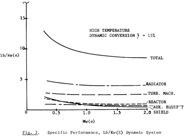
Using potassium as a working fluid over-all plant efficiency can be expected to be about 15%. Operating parameters are summarized below and predicted plant performance (lb/kw(e) is shown in Figure 2.
SPACE POWER SYSTEMS
Turbine inlet - 1900°F Turbine exhaust - 1300°F Turbine efficiency - 75%
Plant efficiency - 15%
A direct condensing radiator in a flat configuration was used. Tubes joined by fins were employed and massive protec- tion against meteorite damage on each tube presumed. Radiator area required at a power level of 300 kw(e) is about 950 sq ft.
DIRECT CONVERSION
The object of this section is to review nuclear-direct conversion systems, establish the state of the art, and ex- plore the ultimate performance potential of high power, high temperature systems. This performance potential will then be compared with dynamic (turbomachinery) systems.
During the past ten years considerable progress has been made in developing materials for thermoelectric and thermionic converters. Thermoelectric devices are now marketed commer- cially and the feasibility of low power nuclear auxiliary power units for space application has already been demonstrated.
SNAP III and SNAP I-A are radioisotope-fueled thermoelectric auxiliary power units (APU's) which have been designed for power levels of 3 watts and 125 watts respectively. SNAP X is a reactor fueled thermoelectric APU which is designed to oper- ate at a power level of 300 watts.
THERMOELECTRIC CONVERSION
The thermoelectric materials used in these SNAP devices are in the Teluride family. They have an upper temperature limit of 1000 to 1200 F and when operating at a heat rejection temperature 500°F will produce an efficiency on the order of 6%. Thus, because of temperature and efficiency limitations, this type of power conversion is restricted to low power lev- els where the radiator area is unimportant.
To take full advantage of the inherent reliability of a power conversion system with no moving parts the above men- tioned devices have no circulating fluids and depend on direct conduction (SNAP III and SNAP X) or radiant heat transfer
(SNAP I-A) from the energy source to the hot junction of the thermoelectric converter. These devices thus are also power level limited by the inherent geometry of such passive heat transfer systems. Nuclear thermoelectric APU's, based on cur- rent state of the art, are considered as interim low power
411
units (< 1 kw(e)) primarily because of their low heat rejection temperature (500°F) and low efficiency.
High temperature materials development work is con- tinuing in this field with the objective of extending the tem- perature range over which thermoelectric materials can be made to operate. But to be competitive with high temperature dy- namic conversion systems, heat rejection temperatures (cold junction) must be on the order of 1200°F.
lency
The following expression defines thermoelectric effic- T - T
i- 7 L - J « h 2 τ ι - (T i "V
where
T.. = hot junction temperature ( K) T
0= cold junction temperature ( K)
Z C*n -QCp
(figure of merit) = ( V V ° h * W p ^
CX = mv / K, n and p
K = w/ K cm, n and p
P =ohm cm, n and p
A figure of merit (Z) of 2.4 x 10 is required to pro- -3 duce an efficiency of 107
oover the temperature range of inter- est (2000 - 1200 F ) . A cascaded thermoelectric design in
SNAP III over a temperature range of interest (1000 - 150 F)operated with a figure of merit of approximately 0.7 x 10 with a corresponding device efficiency of 6?
0. An improvement in temperature potential of 1000°F and figure of merit by a factor of 3.4 is required before thermoelectric materials can be competitive with dynamic conversion systems in high power systems. The figure of merit tends to decrease in semicon- ductors with increasing temperature because they become
"intrinsic"; that is, the heat input causes positive and neg- ative charges to migrate in equal numbers toward the cold junction and no output voltage results.
Considerable development work on basic materials will be
SPACE POWER SYSTEMS
required before thermoelectric conversion can be considered for high power space systems. A significant breakthrough in materials is required to demonstrate performance potential and
subsequent to this a major engineering effort is required to produce a practical long-lived device.
THERMIONIC CONVERSION
Thermionic conversion is the direct conversion scheme which appears most feasible for use in a space power unit.
It is particularly interesting because of its high heat rejec- tion temperature potential, and of course, because of its lack of moving parts.
Here we shall attempt to evaluate thermionic conversion based on theoretical predictions of performance and to deter- mine the ultimate potential of thermionic conversion in space power plants. Much work is now being done on incorporating the cesium vapor filled thermionic converter into the core of a fast reactor so that it will produce electricity directly, and thus the discussion presented herein will center primarily around this concept and evaluate its potential.
PRINCIPLE OF OPERATION
In its simplest form a thermionic converter consists of a hot cathode from which electrons are emitted by thermal energy and a cooler anode which collects the emitted electrons
(Figure 3). The potential (0 ) of the cathode must be greater than that of the anode (0 ) in order to drive electrons through the external circuit. The density of electron current coming off both the cathode and the anode is defined by the Dushman Equation as follows:
J = A T
2E ^ / - KT
where ^
( 2 )J = current density, amp/cm A = 120 2
§ S E2
cm - deg T = °K
e = electron charge, coulomb/electron 0 = work function, volts
415
K = Boltzmann constant
E = base of natural logarithm
In order for electrons to flow from cathode to anode, it can be seen from the foregoing equation that with 0a < 0C
it is necessary that the anode temperature be lower than the cathode temperature. Thus the thermionic converter is basic- ally a heat engine and further analysis by Houston shows that it is subject to the limits of the Carnot cycle and the natur- al losses which occur in any heat engine.
SPACE CHARGE
Because electrons are charged particles, the cloud of electrons between the cathode and the anode forms a space charge barrier. If not provided for, space charge limits current output so markedly that output and efficiency drop drastically.
There are several ways of coping with this problem but only two are considered here, that is close spaced diodes and surface contact ionization.
It can be shown that the effect of space charge can be minimized by spacing the anode and cathode close together.
But to be effective, a spacing in the order of .0004 in. or less, is necessary. A second way of overcoming the space charge barrier which is still passive, is to neutralize the effect of the negative electron charge with positive ions. A converter filled with cesium vapor is commonly used for this purpose. Cesium neutralizes the space charge and may adjust the work function of both the anode and the cathode. Thus, the same material may be used for both cathode and anode sur- faces and this will help to prolong the life of the device.
When considering these two techniques in connection with nuclear power in space one must consider the state of the art in reactor technology as it applies to temperatures attainable in reactors. Liquid-metal-cooled reactors are temperature limited by materials corrosion considerations. Gas-cooled re- actors have higher temperature potential but are unattractive because of their much lower power density. Because a cathode temperature capability of 2000 K appears necessary in order to make thermionic conversion competitive with dynamic methods,
* Reference numbers are shown in parentheses and are listed at the end of the paper.
1
ΓΤ ft O PT fD h-* H M a O H· o o 03 ^ H· N-^ O • o o H a pr < fD fD H CO (t Π) Π) O H o 3 H- a a P rt XJ a* X) fl> H o o 03 O O H a* n> P P no a XJ pu fD P O H O co o h-» 3 H- o a »1 0Q n> rt p- a* fl> fD CO H· P H a P O cr o-h-1 Π
) fD /~N cr H* fD O i o o
o o o h-» 03 a rt P rt O 03 rt -a o 0- fD rt fD 3 XI fD H P3 rt C H fD /•■s rO O O O
rt rr fD o o a < fD H rt fD H H· a rt
P- H· P rt O H H· CO a fD o fD CO CO 03 H jzr^s fD H 03 O- H· 05 rt O H 03 a P- rt a- oc Φ
+
N-^ o HCO pr 03 < H· a M 0Q O O 03 rt H· a 0Q rt a* fD
rt pr fD H fD 03 o rt O H
• > o a* o H· o fD 3 c CO rt cr fD p 03 P- fD cr fD rt S fD fD a h-1 o o 03 rt H· a OQ
CO vj CO ft fD 3 CO 03 o H· H o c h-» 03 rt H· a 0Q O O 0 1—» 03 a rt cr fD rt s fD fD a rt pr fD M fD 03 O rt O H 03 a P- rt a- fD H P 1
M a o H 0- fD H rt O fD X rt fD a o- rt pr fD X) o £ fD H l-1 fD < fD h-1 O Hi
a c o 1—» fD to H rt a-fD H 3 Η· O a Η· O
H te M S 3ί M O a M O Ω O <] M pu H M 5« M 2! PO
5
O H O pö O O 5* M s: M H PC > O M S« O as:
H M 25 O Ω O O£
ss HfD ^. H a os o fD p- H· cr H fD fD rt O S rt fD M fD ^< a H O fD 03 p- rt C a* o O fD CL· co fD O 03 C a rt P-XJ c P rt
a o cr O-Vi fD H hh fD O P- H C O rt H· a- a fD fJQ co rt 4 p a 3 fD fD XI o o C rt H fD n a fD rt a H· rt p 1 h- P- fD p- a H· CO hh H· hh rt fD <<! H • 1
P P- H· P a rt 4 afD P rt h-»
O co co fD CO P a P- rt -a c co H· 3 ■6 H q < fD fD Hi Hi H· O H· fD a O vi • M a o H fD P co H· a 09
Hi T3 fD O rt co rt P ** fD Ό
h-1 O rt O H» fD a fD H H*0Q P O fD • PC H- 0Q ÎT O P rt pr o P- fD O C H H fD a rt P- fD a co H· rt H· fD CO O < fD H H H· P- fD
^ P- H· CO rt H H· cr c rt H· O a < fD H CO c CO rt fD 3 XI fD H P rt C H fD »* K pr ^< rt a- fD co fD fD H) 1
rt O NJ < O H* rt co • M rt H· co O cr < H· o c CO o a fD X P 3 H· a H· a 0Q *j H· 0Q C H fD Ln V» K a4 H· O
s pr H· O 3" H· CO P Ό H1 O rt O Hi rt a* fD co fD CO P 3 fD o c
3 P H 7? fD
-Ö fD H CO P-»û fD y-f\ Hi fD O rt O a fD hh hh H· O H· fD a o ^ o hh
O 3 * H· rt ^ P a P a o P- fD *, O H 7T hh C TSL a HP H fD a rt P- fD a co H· rt H· fD CO K H· rt a-
H· CO P h-1 CO
o rt H· O a /^s
^ H· rt ^ H· a o H fD P CO H· a OQ o C H H fD a rt P- tt> a co H· rt H· fD CO H P a 00 H· TsiL a O P CO pr o 3 a H« a ►*j H· «L0Q ίΤΡ H« CO P
fD ►Q ç P t—»
c H fD -f> >»
%-• o hh O a fD < o h-1 rt •
0Q Hi H O 3 h-1 rt O h-1 O P 3 H x» a- fD fD H fD CO
4> • H pr H· CO hh H· 00 C H fD H· h-* h-1
C co rt H P rt fD CO H- a o H fD P co H· a 0Q o o a < fD H rt fD H fD Hi hh H« O H· fD a o ^<
o hh O P rt 3* O P- fD O C H H fD a rt P- fD a co H· rt ^ C-. o o P a cr fD CO fD fD a
rt a1 fD 3 fD P- H·
s
3 Q 3 XJ h-1 O VÎ fD P- rt O O < fD H O O 3 fD CO X) *î O fD O pr P H cr OQ *<; fD X P 3 H· a H· a 0Q ^ H· 0Q C H fDfD • H pr fD H· a hh h-1 C fD a o fD
rt fD H 3 rt & fD P 3 o c a rt O hh fD a fD H 0Q Vî H fD ►û C H· H fD P- rt O H- O a H· N fD O fD CO H· C 3 H· hh rt pr H· co H· CO
rt fD H 3 CO H fD XJ H fD CO fD a rt O O a P- c o rt H· O a P a P- H P P- H· P rt H· O a h^
O CO CO CD CO w P a P- rt pr fD hh H· hh H pr
cr ^< rt a- fD cr c o ?r H· a 0Q o c H H fD a rt O hh rt pr fD P a o P- fD y*
CO fD o o a P- rt fD H 3 0Q H· < fD CO rt pr fD P 3 o c a rt O hh fD a fD H 0Q rt << a- fD rt pr H· H P- P a P- Ht O c H rt pr
H fD rt C H a fD P- rt O rt a- fD O P rt a' o P- fD
Hi H O 3 rt pr fD O P rt 3-
O P- fD P a P- o < fD H O O 3 fD rt
rt pr fD hh H· H CO rt rt fD H 3 H· CO rt pr fD fD 3 fD H 0Q ^ H fD 3*·Ρ fD CO XJ P O fD O 3" P H 0Q fD cr P H H H· fD H V* rt 3* fD
C H· H fD P- rt O fD < P XJ o H P rt fD fD h-1 fD O rt H O 3 co
H· 3 fD h-1 fD O rt H O P- fD CO P 3 P- h^ fD P P- co • H 3* fD P- fD 3 O 3 H·
3 P rt O H H· CO 3 P P- fD C XJ P co hh O 1 h- 4 h- O K co
H pr fD 3 C 3 fD H P rt O H H· CO 3 P P- fD C XI o hh XI o s fD H O C rt XI c rt 3 H·
3 C co rt pr fD 1 h- O CO CO fD CO
C/Vv 1 C-. o r fD
<
+
ro W H O 1 C P < P fD+
ro ^ H P+
!* -f PO+
Mκ-s < O 1 < P s-x /~\ CH O | C-i P N-X 1 PO /-v c. o 1 c^ P N-^ ho /-s u> s»**
PC o c co rt O 3 *> H H· rt fD co rt 3* fD fD »û C P rt H· O 3 P co hh O h-1 h-» O K co ··
M hh hh H· O H· fD 3 O ^ H· CO XJ O 3 fD H O P rt P- H· < H· P- fD P- cr ^ rt pr fD fD 3 fD H 0Q ^ H· 3 P 3 P-
W •rj ►n M O M w a o HÜ
hh H· h-» h-1 fD P- O O 3 < fD H rt fD H •
rt pr fD O h-1 O CO fD CO XI P o fD P- P- H·
O P- fD • O 3 fD 3 fD fD P-
O 3 1 h- V! O o 3 co H· P- fD H rt pr fD 3 rt pr fD OQ P CO
rt 3- fD H 3 P I—» fD X XI P 3 co H· O 3 fD h-1 H· 3 H·
3 P rt fD hh C H rt 3* fD H CO fD H H· O C CO o o 3 co H« P- fD H P rt H· O 3 O Hi
XI fD H P rt C H fD CO P H fD XI O CO CO Η· er h-· fD • ^ P er H Η· o P rt H· O 3 XJ H O cr
H· 3 CO P* h-1 P rt fD P- hh H O 3 rt 3- fD h-1 H· HD C H· P- 3 fD rt P h-1 O O o h-4
P 3 rt cr h-^i fD 3 co o o 3 cr H· 3 fD P- S H· rt pr
rt 3* fD P 3 O P- fD «* pr H· 0Q pr rt fD 3 1
rt 3- fD O P rt pr o P- fD 3 c CO rt cr fD P 3 H· 3 rt fD OQ H P h-4 XI P H rt O hh rt £T fD hh C fD h-» fD h-· fD 3 fD 3 rt K 3^ fD H fD "
CO > n m -σ
o
m TO CO -< Co m COcause materials technology is better developed at the lower temperature. It may be possible to use an E.M. pump and sodi- um or NaK as a coolant. Research work has been under way at LASL on this concept, and private industry has also shown an interest in the approach.
The core configuration might typically be made up of fuel rods whose surface would be the cathode. Individual fuel rods would be surrounded by concentric cylinders (anodes) which are cooled by a circulating liquid metal. (Figure 6.) The outside surface of the anode cylinder could be covered by a thin electrical insulation layer. By properly insulating and spacing the cathodes and anodes a series, parallel array can be arranged to improve output voltage characteristics.
In any high power nuclear space power plant, the radiator is a component of prime importance. Radiator area is extremely sensitive to rejection temperature and here the thermionic de- vice appears to have an advantage. A close look at anode con- ditions shows however that there is an upper limit to anode ( . temperature which is related to anode work function. Houston shows that device efficiency is sensitive to anode temperature and work function and thus cannot be ignored, that is, for an anode work function of one volt the maximum permissible temper- ature is 640°K (690°F). At higher anode temperatures, the efficiency decreases rapidly due to heavy back emission. If one uses an anode work function of 1.7 volts, the allowable anode temperature becomes 1050 K (1400°F) with a corresponding back emission of one ampere. Assuming a coolant temperature drop of 100°F and a thermal gradient of 50°F from anode surface to coolant we can thus expect the radiator temperature to be an average of 1300°F. This compares directly with radiator temperature for Rankine cycles using potassium as a working fluid, (turbine inlet = 1900°F, turbine exhaust = 1300°F).
If one assumes the same meteorite protection, radiator areas and weights are equal on strictly a temperature basis.
We must then look at system efficiency as it affects radiator size and weighto
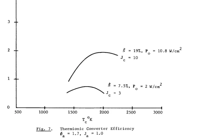
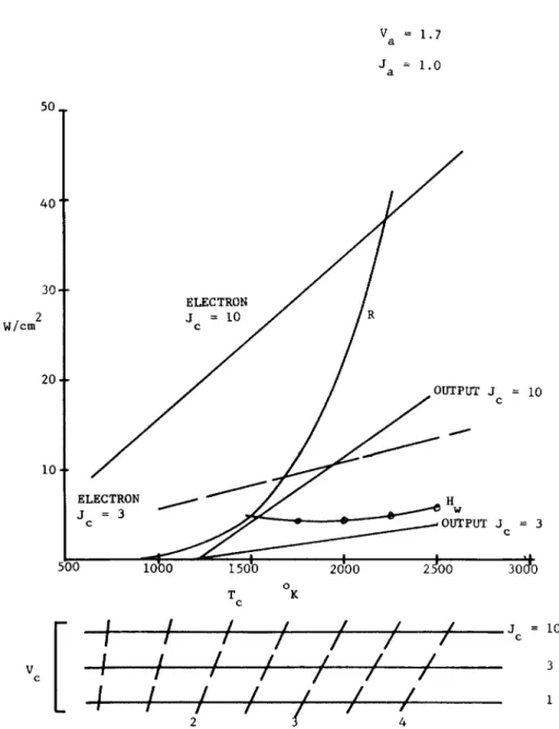
Cathode current densities of 3 amps/sq cm are obtainable and Jc of 10-20 amps/sq cm are reported in laboratory experi- ments. Figure 7 is a plot of calculated device efficiencies with 0a = 1.7. This plot is similar to Houston's analysis ex- cept that back emission from the anode, re-radiation of thermal energy (E = 0o5) back to the cathode, and I R losses were con- sidered. These losses are summarized in Figure 8. It is now meaningful to establish reactor power density and from this to determine reactor core size. If a typical geometry is laid
416
SPACE POWER SYSTEMS
out using 1/2 in. diameter cathodes on 3/4 in. centers we find that it is possible to have 30,000 sq cm of cathode surface per cubic foot of core. Fuel occupies 35% of the core volume and with UC as a fuel material the critical volume becomes 1.04 cu ft in a cylindrical geometry (L/D = 1) with a 4 cm BeO reflec- tor (mc = 132 Kg U-235). Figure 9 illustrates over-all reactor geometry.
The core geometry was selected on considerations of power density and criticality requirements. Spacing between fuel pin surfaces was determined by estimating required cladding -30 mils, gap -20 mils, anode thickness -60 mils, and separa- tion -30 mils» Spacing between fuel surfaces is thus .25 inches. It can be shown that cathode surface is greatest when fuel pin diameter also equals .25 inches. This means however that the fuel (UC) would only occupy 10% of the core volume and as is shown in Figure 10 criticality is difficult to ob- tain. Using a fuel pin diameter of one half inch reduces cathode surface by only 11% and raises fuel volume in the core to 35%.
The thermionic reactor described with a cathode current density of 3 amps/sq cm has a corresponding thermionic power density of 62.4 kw(e)/cu ft. This core with J = 10 amps, sq cm has a thermionic power density of 337 kw(e)/cu ft. The power density attainable in a liquid metal cooled core (30 Mw^V cu ft) combined with a Rankine cycle ( £ = 15%) is 4,500 kw(e) cu ft. In order to compare the two system concepts fully how- ever, it is necessary to evaluate the effect of reactor weight, shield weight and radiator size and weight.
An estimate has been made of power plant specific weight (lb/kw(e)) by scaling this same thermionic geometry over a range of size and power. The results are shown in Figures 11 and 12. A comparison to the specific weight of a dynamic con- version plant is shown in Figure 13.
The shadow shield weight was calculated based on shield-
1 1 ing a 10 compartment with a separation distance of 50 . Radi-
ator weight was based on using massive protection against me- teorites and was adjusted on a lb/kw basis by system efficiency.
No attempt was made to adjust reactor L/D ratio. Power density in the thermionic core is considered optimistic because no al- lowance was made for leads, insulating spacers and power and temperature variation with flux density and reactor life.
Locating thermionic converters directly in the core has the effect of reducing fuel density» In order to go critical it is thus necessary to make the core larger and increase fuel inventory. Figure 14 illustrates the difference in fuel inven-
417
tory required for a fast reactor (65% fuel volume) and a therm- ionic reactor (35% fuel volume). The fuel inventory in the thermionic reactor is significantly greater.
The writer has been informed that recent experiments have been performed, using UC ZrC as a cathode material, which re- sulted in a cathode power density of 18 watts/sq cm.^ ' Cathode temperature was estimated to be 2100 C. Emissivity has been measured at 0.8 on this compound by LASL. (Note that the fore-
going theoretical analysis assumed E = 0.5.) Eventual cathode power densities of 20 to 30 watts at this same temperature
(2100°C) are predicted.
Efficiency at the conditions stated above are calculated to be 9% and 11.7% at 20 and 30 watts per sq cm respectively.
Lowered efficiency as compared to previously calculated cases is due primarily to the high cathode anode emissivity (0.8).
The power plant specific performance at these high cathode power densities is plotted in Figure 15. Note the overriding effect of radiator weight as it is influenced by efficiency. Development work has been initiated to include radiation baffles between cathode and anode to reduce thermal radiation losses and thus improve efficiency. The thermionic system without radiation baffles is again seen to be comparable in performance potential to the dynamic power plant.
COMPLETELY STATIC NUCLEAR THERMIONIC CONVERTER A completely static, nuclear, thermionic, space power plant can be visualized which employs no circulating fluids and thus enhances reliability. This can be done by utilizing a fast uranium carbide fueled reactor with a high temperature capability.
The surface of the reactor could be the cathode and the anode would be made up of a shell around the reactor with the void volume between filled with cesium vapor. The anode could be cooled by radiation directly to space and the reactor reflector controlled. An appropriate high temperature material such as tungsten, might be used for cathode and anode surfaces.
Such a plant with the core diluted with carbon to increase surface area would be a cylinder approximately two feet in di- ameter by two feet in length. Its power rating would range from 16 to 32 kw(e) at Jc = 3 and Jc = 10 respectively, and its un- shielded weight would be approximately 1500 pounds. This type of plant is power level limited by geometry and shows relatively poor potential on a lb/kwe basis.
418
SPACE POWER SYSTEMS
REFERENCES
J. M. Houston, "Theoretical Efficiency of the Thermionic Converter,
1'' Journal of Applied Physics, Vol. 30, No. 4, April, 1959
Dr. G. Grover, LASL, Telecon, 7 Sept. 1960
10,000
1,000 t
100 PSIA
10 k
1.0
[
I [/ y
£ /
1 / >
/L
P * He S ^
Rb
*
LiJ
7\
* CRIT. PRESSURE
600 1000
T°
F1400 1800 2000
Fig. I« Vapor Pressure of Possible Working Fluids
419
ro o
1(4
lb/kw(e)
5 4
HIGH TEMPERATURE
DYNAMIC CONVERSION f = 15%
TOTAL
..RADIATOR
—TURB. MACH.
REACTOR
^ ^ A U X . EQUIP'T 2.0 SHIELD
>
n
o
-<
Fig. 2. Specific Performance, Lb/Kw(E) Dynamic System
SPACE POWER SYSTEMS
CATHODE ANODE
Θ
wvw
LOADFERMI LEVEL
FERMI
♦ LEVEL
F i g . 3 . Thermionic Conversion
421