Correcting Excessive Overbites
with V-Bend Activations of Super Elastic Wires
An Exciting Change
A Comparison of the IPS d.SIGN and
A Visionary Leader: Dr. Paul Weigl
T
he tremendous proliferation of implant services worldwide has created a need for simplifi ed and more predictable treatment guidance modalities. There are currently a number of surgical guide platforms that are available, but most systems are strictly limited to specific implant catalogues, typically the products sold by the surgical guide sponsor. Other surgical guides are open systems and allow the practitioner to use any selected dental implant. The practitioner has the options of freehand, partially guided, and fully guided implant placement surgery. Guided surgery results in more accurate results than freehand surgery. Computerised treatment planning and guided surgery improve accuracy, predictability and patient care.Patient-centred treatment planning Given the wide selection of high-quality implants that can be utilised by the dental practitioner, it makes more sense to develop a treatment plan based on the patient’s needs and anatomic suitability rather than on a specifi c implant manufacturer’s product lines, due to the large variation in cost and the regional disparity in product access. Thus, the ideal guidance system can be adapted to a variety of implant brands and types, off ering recommendations that are patient-centred rather than product- centred.
The SMART Guide Technology System (dicomLAB Dental Ltd., Szeged, Hungary) provides a complete case analysis and preparation shortly after imaging, enabling
immediate treatment planning for any type of implant placement; it is possible to set the implant length with 0.5mm increments and the diameter with 0.1mm accuracy. The surgical protocol of the system is entirely dependent on the properties of the implant which is selected by the practitioner. The shape of the implant is also at the discretion of the dentist – conical or parallel shapes can be selected.
CBCT and intraoral impression
The following presentation is a detailed, step-by-step presentation of a case where planning and surgery were both accomplished with the assistance of the SMART Guide system.
A 39-year-old female patient presented a broken left upper fi rst bicuspid, tooth 24.
The tooth has had endodontic treatment;
a subsequent vertical fracture of the root and unrestorable coronal structures made the case for an implant treatment the best choice.
The remaining dental structures of tooth 24 were extracted. In order to avoid any complications due to residual bacteria or possible periapical or periradicular infection, a two-month healing time was mandated.
After the initial healing step, a CBCT was taken, and an intraoral impression of the patient was made with a custom-made plastic impression tray and C-silicone. This is the SMART Guide Simple CBCT Protocol.
This approach does have some limitations as the superimposition of the CBCT to the silicone impression requires the presence of a minimum of eight sound teeth to be present as reference points on the dental arch to be treated. The silicone impression must be scanned with an extraoral scanner
Guided Implantology:
the SMART Guide
By Dr. George Freedman and Dr. Mark Antal
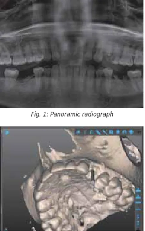
Fig. 1: Panoramic radiograph
Fig. 3: Virtual model of #24 fractured with SMART Guide visualisation
Fig. 2: Virtual model of #24 fractured
to the impression. Another option is to use an intraoral scanner. The same limitations regarding sound teeth apply, however. The reference teeth must be sound or restored with metal-free restorations; any metal restorative components, such as amalgam fillings, PFM crowns or bridges and/or metal posts interfere with the CBCT data acquisition.
After the CBCT of the patient and the scanned impression were completed, both data sets were uploaded, without patient identifying information, to the SMART Cloud.
Then the SMART Guide centre checked the quality of the pictures.
In cases where the patient is completely edentulous or where there are not enough metal-free, sound or restored teeth to provide the required minimum eight reference points, the “Double CBCT” technique can be employed. This procedure consists of an initial impression of the patient. The radio- opaque gutta percha markers are positioned on the tray. The patient then wears this tray intraorally during the second CBCT. Thus, there are two separate CBCTs, one of the gutta percha marked tray extraorally and one of the marked tray intraorally – hence
“Double CBCT”. This process ensures a precise fi t in those cases where the number of sound tooth reference points are limited.
Assisted treatment planning
Once the dicomLAB Dental SMART Guide centre has prepared the case, the operator receives a notifi cation e-mail or text. This is typically within approximately four hours after successful data upload. The practitioner then downloads the patient’s data to the practice computer on which the Smart Guide software has previously been installed. It is now possible to plan the optimal positioning (location, angulation, depth, and diameter) of the implant, considering the implant properties (length, diameter, and shape) as indicated above.
the earlier extracted left upper fi rst premolar with an implant and an implant-borne crown are demonstrated. The software makes it possible to visualise the bone, soft tissue, and intraoral impression taken of the patient. The software then suggests a crown shape, which assists with the planning of the implant angulation and the ideal emergence profi le of the restorative crown. The recommended shape considers the anatomical properties of the adjacent and opposing teeth, and the soft tissue condition. In cases where screw-retained crowns are planned, this process is essential in ensuring the proper location for optimal angulation and access of the retention screw.
Fig. 4: Planned implant in OV view
Fig. 7: Zoomed-in view of the planned implant in SMART Guide software
Fig. 9: Digital tooth setup visualisation in the SMART Guide Software
Fig. 10: Implant for fractured #24 planned
Fig. 11: Planned implant in the 3D Visualisation in the SMART Guide Software
Fig. 8: Zoomed-in view of the planned implant in SMART Guide software
Fig. 5: Planned implant in OV and MD view
Fig. 6: Panoramic view of the planned implant in the SMART Guide software
Once the planning phase is completed, it is possible to ask for a treatment plan review by a contracted expert implant specialist within the SMART Guide System who is able to mentor the practitioner. This approach off ers confi rmation of treatment approach and direction prior to beginning any surgical steps. For those who are less experienced in treatment planning, this is an invaluable and highly protective service. A comprehensive Preplan Service, which begins immediately after data uploading, is also available.
In all cases, however, the fi nal decisions are always in the operator’s hands. Further planning and modifications are always possible before the SMART Surgical Guide is ordered.
Surgical guide and protocol
A short time after it is ordered, the printed surgical guide arrives at the practice. It is a good idea to sterilise it in an autoclave.
Along with the printed surgical guide, the operator is provided with a specifi c surgical protocol which matches the planned implant.
Fig. 13: First preview picture of the case in SMART Cloud
Fig. 16: Abutment in the model
Fig. 20: Preparation
Fig. 21: Start long drill
Fig. 22: The fi rst drill goes in with the spoon to stabilise the drill
Fig. 23: The fi rst drill with its spoon
Fig. 24: Inserting the fi rst drill through the surgical guide after the start drill
Fig. 17: The surgical guide after arrival
Fig. 18: The surgical guide after sterilisation
Fig. 19: The surgical guide in the patient’s mouth
Fig. 15: SMART Guide Surgical Protocol Fig. 14: Second preview picture of the case in
SMART Cloud Fig. 12: SMART Impression tray visualisation in the
SMART Guide Software
surgery, the sequence that is suggested on the attached drilling protocol chart should be followed. The Surgical Kit of the SMART Guide System consists of 20mm, 24mm and 28mm long, each with a diameter of 2.0; 2.5;
3.0; and 3.5mm.
Fig. 25: The second drill with its spoon
Fig. 35: Healing cap insertion
Fig. 36: Post-operative panoramic radiograph
Figs. 37-38: Healing Fig. 26: Inserting the second drill
Fig. 27: The third drill with the corresponding spoon
Figs. 29-33: Implant insertion
Fig. 34: Checking vertical position through the surgical guide with depth control Fig. 28: After the preparation, use the implant
drills up to the last drills needed
Fig. 29
Fig. 30
Fig. 31
Fig. 32
Fig. 33
The fi nal drilling step is done with the fi nal core drill of the selected implant system at the proper depth and diameter to ensure perfect implant placement. The fi nal implant drill can also be used without the surgical guide, since the direction and depth of the bone preparation are already pre- established with the SMART guide. The bony housing is already prepared to a size which almost matches that of the intended implant.
Fig. 37
Fig. 38
About the authors
Predictable and versatile
The SMART Guide Technology offers a versatile implant placement guidance system that can be adapted to most implant brands and types, making implant surgery patient- centred rather than product-centred, more predictable, and more effi cient. DA
Dr. George Freedman is a founder and past president of the American Academy of Cosmetic Dentistry. Besides being a co-founder of the Canadian Academy for Esthetic Dentistry, and the International Academy for Dental Facial Esthetics, he has also served as a diplomate and chair of the American Board of Aesthetic Dentistry.
He is an adjunct professor of dental medicine at Western University in Pomona, California, and professor and programme director at BPP University in London for the master’s programme in clinical dentistry in restorative and cosmetic dentistry.
Dr. Freedman has authored or co-authored 14 textbooks and more than 800 dental articles, and lectures internationally. He maintains a private practice limited to aesthetic dentistry in Toronto, Canada.
Dr. Mark Antal is a senior lecturer at the Faculty of Dentistry at the University of Szeged in Hungary. After earning his Doctorate of Medicine in Dentistry, he specialised in operative dentistry and oral surgery, with internships in Martin-Luther University of Halle-Wittenberg in Germany, and Boston University and New York University in the United States.
Besides being a member of the education committee at FDI World Dental Federation, Dr. Antal is also an honorary lifelong member of the International Association of Dental Students. His special research interests are in aesthetic dentistry, dental implantology, and tobacco cessation in preventive oral medicine.
Fig. 41: Abutment inserted
Fig. 42: Before the fi nal step
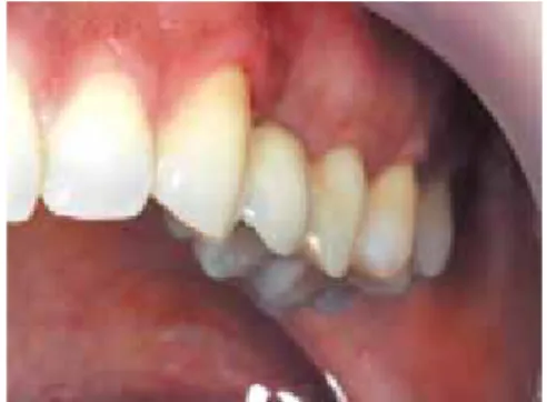
Fig. 43: The missing #24 tooth replaced using SMART Guide
Fig. 40: Abutment Fig. 39: Implant is exposed