A NEW METHOD TO DETERMINE THE OPTIMAL ORIENTATION OF SLIM MODIOLAR COCHLEAR IMPLANT
ELECTRODE ARRAY INSERTION
HORVÁTH Bence1, 2, PERÉNYI Ádám2, MOLNÁR Fiona Anna3, CSANÁDY Miklós2, KISS József Géza2, ROVÓ László2
1University of Szeged, Doctoral School of Clinical Medicine, Szeged
2University of Szeged, Department of Oto-Rhino-Laryngology and Head-Neck Surgery, Szeged
3University of Szeged, Faculty of Medicine, Szeged
ÚJ MÓDSZER A VÉKONY PERIMODIOLÁRIS COCHLEARIS IMPLANTÁTUMELEKTRÓDA IDEÁLIS BEVEZETÉSI IRÁNYÁNAK MEGHATÁROZÁSÁRA Horváth B, Perényi Á, MD; Molnár FA, Csanády M, MD;
Kiss J, MD, PhD; G, MD, PhD; Rovó L, MD, PhD Ideggyogy Sz 2021;74(5–6):191–195.
Háttér és cél – Célunk az volt, hogy meghatározzuk a vékony perimodioláris elektróda bevezetésének opti- mális irányát a mûtéti orientációt segítô anatómiai struk- túrákhoz képest, és könnyen használható módszert dol- gozzunk ki az implantátum mûtétjének segítésére.
Bizonyos esetekben az elektródasor a cochleán belül visszafordul. Véleményünk szerint ennek a problémának az egyik lehetséges oka az elektródasor kedvezôtlen bevezetési iránya. Módszerünket egy kiválasztott speciális eseten mutatjuk be.
Módszerek– A méréshez az egyik cochlearis implantá- tummal ellátott betegünk preoperatív CT-felvételét használtuk. A felvételt egy nyílt forráskódú és ingyenesen használható képmegjelenítô szoftverrel, a 3D Slicerrel dolgoztuk fel. A mérési módszer kezdeti lépése az üllô rövid nyúlványa csúcsának a kijelölése. Ezután létre kell hozni a cochlearis nézetet, és ezen a nézeten két egye - nes vonalat berajzolni: az elsô vonal az elektródasor vezetôjét, a második vonal az orientációs jelzôt jelenti.
A meghatározni kívánt szög az orientációs jelzô és az üllô rövid nyúlványát a korábban felvitt egyenesek metszéspontjával összekötô egyenes által bezárt szög.
A számításhoz egy saját python kódot használtunk.
Eredmények– Az algoritmusunk eredménye 46,605°
volt. Ennek validálásához a hallócsontokat és a hártyás labirintust kiszegmentáltuk a CT-felvételbôl, majd ebbôl készítettünk egy 3D-s modellt, amelyben láthatjuk az elôzô vonalak helyzetét az anatómiai struktúrákhoz képest. Ezután elforgattuk a 3D-s modellt a vonalakkal Background and purpose– Our goal was to determine
the optimal orientation of insertion of the Slim Modiolar electrode and develop an easy-to-use method to aid implantation surgery. In some instances, the electrode arrays cannot be inserted in their full length. This can lead to buckling, interscalar dislocation or tip fold-over. In our opinion, one of the possible reasons of tip fold-over is unfavourable orientation of the electrode array. Our goal was to determine the optimal orientation of the Slim Modiolar electrode array relative to clear surgical land- marks and present our method in one specified case.
Methods– For the measurement, we used the preopera- tive CT scan of one of our cochlear implant patients.
These images were processed by an open source and free image visualization software: 3D Slicer. In the first step we marked the tip of the incus short process and then created the cochlear view. On this view we drew two straight lines: the first line represented the insertion guide of the cochlear implant and the second line was the orientation marker (winglet). We determined the angle enclosed by winglet and the line between the tip of the incus short process and the cross-section of previously created two lines. For the calculation we used a self-made python code.
Results– The result of our algorithm for the angle was 46.6055°. To validate this result, we segmented, from the CT scan, the auditory ossicles and the membranaceous labyrinth. From this segmentation we generated a 3D reconstruction. On the 3D view, we can see the position of
Correspondent: HORVÁTH Bence, Szegedi Tudományegyetem, Szent-Györgyi Albert Klinikai Központ, Fül-orr-gégészeti és Fej-nyaksebészeti Klinika; 6723 Szeged, Gyöngyvirág u. 20/B, 8.em./24.
Telefon: +36302962766, e-mail: h256426@stud.u-szeged.hu https://www.orcid.org/0000-0002-8367-4259
| English| https://doi.org/10.18071/isz.74.0191 | www.elitmed.hu
C
ochlear implantation is an effective hearing rehabilitation technique for patients with severe-to-profound sensorineural hearing loss1. The spiral ganglion cells are directly stimulated by elec- trical signals that are transmitted via an electrode array that is surgically inserted into the cochlea.This can lead to buckling, interscalar dislocation or tip-fold over2–5. Another possible hazard is short circuiting and implant loss.
The highest proportion of the cochlear implants (CI) that were implanted at the Department of Otorhinolaryngology, Head and Neck Surgery, University of Szeged were Cochlear™ Nucleus®
CI532 and CI632 since 2015. Both devices are mounted with one of the thinnest perimodiolar elec- trode arrays (Slim Modiolar)6. Periomodiolar means that the electrode array is pre-curved and this property predisposes its close-to-modiolus or modi- olus hugging position. The reason our team has pre- ferred this specific electrode array is: its potential to be superior to the thicker Contour Advance and straight electrode with regards to proximity to the modiolus; lower energy consumption for stimula- tion and less trauma to the cochlea7–10. On the other hand, although easy after proper training, the inser- tion procedure can be challenging11. An adverse event, tip fold-over of the Slim Modiolar electrode, has been reported with higher incidence than with other electrodes.
In our opinion, one of the possible reasons of tip fold-over is unfavourable orientation of the elec- trode array. Thus, proper orientation of the elec- trode during insertion can be considered a possible method of prevention of tip fold-over. Our goal was to determine the optimal orientation of the Slim Modiolar array relative to clear surgical landmarks and present our method in one selected case.
Methods
For the measurement, we used the preoperative CT scan (slice thickness 0.6 mm, no gap, bone kernel) of one of our cochlear implant patients. Selection criteria were good quality high-resolution CT scan of the temporal bones, without a reported anatomi- cal malformation and uncomplicated cochlear implantation with a perimodiolar (Cochlear™ Slim Modiolar) electrode array. The good quality of the CT scan and the normal anatomy of the selected 70- year-old male subject was confirmed by a radiolo- gist who obtained subspecialisation in head and neck imaging. These images were processed by an open source and free image visualization software:
3D Slicer (version: 4.10.1, operating system Win10)12–14, that is available on all platforms (Win, Mac, Linux). This software is able to read many image file formats, including DICOM. After having imported the DICOM files, we converted the image series into single “.nrrd” files, the proprietary file format of 3D Slicer. By doing this conversion process, 3D Slicer anonymizes the images, after which the images do not contain any personal infor- mation on the patient.
In our case study we present our semi-automatic algorithm to perform the measurements related to visible surgical landmarks.
In the first step, the user created the cochlear view (Plane A)15. The basal turn of the cochlea is best seen in one special plane, i.e. the cochlear view. This plane can be easily created by rotating the coronal plane. The plane of the cochlear view is practically the plane of the proper electrode inser- tion.
Subsequently, the user created two straight lines:
the first line represented the insertion guide of the
együtt, hogy az elektródasor vezetôje pontként ábrá- zolódjon. A szöget ImageJ-jel megmérve az eredmény 46,599° lett.
Következtetés– Megállapítottuk, hogy módszerünk egyszerû, gyors és idôhatékony. A mûtétet minden beteg számára egyedileg lehet megtervezni a mûtét elôtt ké szí - tett CT-felvétel alapján, és segítségével biztonságosabbá tehetô a vékony perimodioláris elektróda implantációja.
A jövôben tervezzük, hogy minden vékony perimodioláris elektródával folytatott mûtét elôtt elvégezzük a méré - seket, ezáltal növelve az implantáció sikerességét.
Kulcsszavak: cochlearis implantáció, mûtéti tervezés, képfeldolgozás, tip-fold over, Slim Modiolar
the previous lines relative to the anatomical structures. After this we rotated the 3D model together with the lines so that the insertion guide forms a dot. In this view, the angle was measured with ImageJ and the result was 46.599°.
Conclusion– We found that our method is easy, fast, and time-efficient. The surgery can be planned individually for each patient, based on their routine preoperative CT scan of the temporal bone, and the implantation procedure can be made safer. In the future we plan to use this method for all cochlear implantation surgeries, where the Slim Modiolar electrode is used.
Keywords: cochlear implantation, surgery planning, image processing, tip-fold over, Slim Modiolar
cochlear implant (Line I.) and the second line the orientation marker (winglet, Line II.) shown in Figure 1.A. These two lines are perpendicular to each other and intersect at the round window.
Finally, the user marked the tip of the short process of the incus (Figure 1.B). The incus short process was depicted on the CT scan and was connected with the cross-section of the winglet and the inser- tion guide. This is the line to which we compare the position of the winglet.
The above mentioned three parameters are suffi- cient to calculate the optimal angle of the orienta- tion marker. We determined the angle enclosed by Line II. and the line between the tip of the incus short process and the cross-section of Line I. and Line II. This third (virtual) line is coded as Line III.
Although the surgeon is able to visualize the depth
of angles and planning the surgery is easier and more accurate in one plane (2D view). For this rea- son, we projected Line I. and Line II. onto one com- mon plane (Plane B). This plane is perpendicular to the Plane A Line I., and parallel with Line II.
(Figure 2).
Plane B will be outside the real surgical view.
Nevertheless, we do not need to move the Plane B (projection plane) into the view of the surgery, because the projection does not change the meas- ured angle. For this mathematic problem, we wrote an algorithm in python (Python 3), to quantify the angle enclosed between these lines in degrees.
Results
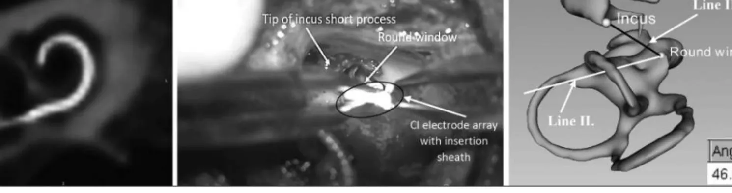
The good quality of the CT scan of the right tempo- ral bone was confirmed by a trained head and neck radiologist. The radiologist also confirmed that the temporal bone was free of anatomical malforma- tion, which was consistent with the official radiolo- gist’s report. Each step by the user (determination of the landmarks, lines and planes) was approved by the radiologist. The postoperative radiography showed unremarkable position of the electrode inside the cochlea (Figure 3.A). On Figure 3.Bis shown a microscopic view with the landmarks (incus short process, round window) and the elec- trode array with the insertion sheath. The result of our algorithm for the angle between the projected lines (incus–round window and insertion direction) was 46.605 degrees. To validate this result, with 3D Slicer we segmented the auditory ossicles and the Figure 1. A.The cochlear view of the right cochlea
(Plane A), and the lines defined as Line I. (insertion guide) and Line II. (orientation marker, called winglet), B.the tip of the incus short process on the axial plane in the right temporal bone (arrow)
A
B
Figure 2.Plane A: the cochlear view of the right cochlea with the drawn lines (Line I. and Line II.) as shown by arrows, Plane B: the projection plane that contains the line of the orientation marker (Line II.). The user projected the reference line onto
membranaceous labyrinth (on CT the liquid and air are hypodense). From this segmentation, we gene - ra ted a 3D reconstruction. On the 3D view we can see the position of the lines, as shown previously on Figure 1.Aand Figure 2(Line I., Line II.) relative to the anatomical structures (Figure 1.B).
Afterwards, we rotated the 3D model together with the lines (Line I., Line II. and Line III.) so that the insertion guide (Line I.) forms a dot as shown in Figure 3.C. In this view the angle was measured with ImageJ and the result was 46.599°.
Discussion
Our goal was to determine the optimal orientation of insertion of the Slim Modiolar electrode and develop an easy-to-use method to aid implant plan- ning and surgery. Reference structures that can be clearly visualized during surgery and clearly noticed on the CT image, are essential. The short process of the incus and the round window were chosen as clear anatomical landmarks, due to their
nature of visibility during routine cochlear implant surgery via posterior tympanotomy. The surgeon is able to detect these landmarks and relate the posi- tion of the electrode array to them. With this meas- urement tool we aimed to effectively prevent elec- trode tip fold-over2, 4, 5, a relatively common adverse event from Slim Modiolar electrode. We assume that a possible reason of tip fold-over is un fa vou - rable orientation of electrode during insertion.
Other reasons include the various anatomical struc- ture of cochlea, for example: size, orientation, length, and malformations16, so it is necessary to individually plan the surgery beforehand.
In this paper we presented a new method to determine the optimal insertion angle of the Slim Modiolar cochlear implant electrode. We found that our method is easy, fast, and time-efficient. The surgery can be planned individually for each patient based on their routine preoperative CT scan of the temporal bone and the implantation procedure can be made more safe. In the future, we plan to use this method for all cochlear implantation surgeries, where the Slim Modiolar electrode was used.
Figure 3. A.Postoperative 3D volume tomography of the inserted electrode, reconstruction in the cochlear view. B.The microscopic view through the posterior tympanotomy to the landmarks (incus short process, round window) and orientation of the electrode array with the insertion sheath.C.3D model of the auditory ossicles (i.e. incus, malleus and anterior crus of stapes) and the membranaceous labyrinth. Black line: reference line (Line III.), white line: orientation marker (Line II.), the angle (measured with ImageJ) was approx. 47 degrees
A B C
REFERENCES
1.Clark GM. The multiple-channel cochlear implant: the interface between sound and the central nervous system for hearing, speech, and language in deaf people-a personal perspective. Philos Trans R Soc Lond B Biol Sci 2006;
361(1469):791-810. https://doi.org/10.1098/rstb.2005.1782 2.Zuniga MG, Rivas A, Hedley-Williams A, Gifford RH,
Dwyer R, Dawant BM, et al. Fold-over in cochlear implan- tation: Case series. Otol Neurotol 2017;38(2):199-206.
https://doi.org/10.1097/MAO.0000000000001283 3.Dimak B, Nagy R, Perenyi A, Jarabin JA, Schulcz R,
Csanady M, et al. Review of electrode placement with the Slim Modiolar Electrode: identification and management.
Ideggyogy Sz 2020;73(1-2):53-9.
https://doi.org/10.18071/isz.73.0053
4.Ramos-Macias A, Falcon-Gonzalez JC. Mechanisms of electrode fold-over in cochlear implant surgery when using a flexible and slim perimodiolar electrode array. Acta Otolaryngol 2017;137(11):1129-35.
https://doi.org/10.1080/00016489.2016.1271449
5.Sabban D, Parodi M, Blanchard M, Ettienne V, Rouillon I,
Loundon N. Intra-cochlear electrode tip fold-over. Coch - lear Implants Int 2018;19(4):225-9.
https://doi.org/10.1080/14670100.2018.1427823
6.Gstoettner WK, Adunka O, Franz P, Hamzavi J, Plenk H, Susani M, et al.Perimodiolar electrodes in cochlear imp- lant surgery. Acta Otolaryngol 2001;121(2):216-9.
https://doi.org/10.1080/000164801300043569
7.Perenyi A, Toth F, Dimak B, Nagy R, Schoerg P, Jori J, et al. Electrophysiological measurements with electrode types of different perimodiolar properties and the same cochlear implant electronics - a retrospective comparison study. J Otolaryngol Head Neck Surg 2019;48(1):46.
https://doi.org/10.1186/s40463-019-0361-8
8.Roland PS, Wright CG. Surgical aspects of cochlear imp- lantation: mechanisms of insertional trauma. Adv Otor hi - no laryngol 2006;64:11-30.
https://doi.org/10.1159/000094642
9.Skarzynski H, Matusiak M, Lorens A, Furmanek M, Pilka A, Skarzynski PH. Preservation of cochlear struc- tures and hea ring when using the Nucleus Slim Straight (CI422) electrode in children. J Laryngol Otol 2016;
130(4):332-9.
https://doi.org/10.1017/S0022215115003436
10.Adunka OF, Pillsbury HC, Kiefer J. Combining perimodi- olar electrode placement and atraumatic insertion properti-
es in cochlear implantation - fact or fantasy? Acta Oto la - ryn gol 2006;126(5):475-82.
https://doi.org/10.1080/00016480500437393
11.Dhanasingh A. Why pre-curved modiolar hugging electro- des only cover the basal turn of the cochlea and not beyond that? J Int Adv Otol 2018;14(3):376-81.
https://doi.org/10.5152/iao.2018.5831
12.Bruns N. 3D Slicer: Universal 3D visualization software.
Unfallchirurg 2019;122(8):662-3.
https://doi.org/10.1007/s00113-019-0654-4
13.Fedorov A, Beichel R, Kalpathy-Cramer J, Finet J, Fillion- Robin JC, Pujol S, et al.Kikinis, 3D Slicer as an image computing platform for the Quantitative Imaging Network.
Magn Reson Imaging 2012;30(9):1323-41.
https://doi.org/10.1016/j.mri.2012.05.001
14.Nagy A, Ódor B, Beöthy FO, Perényi Á, Rovó L, Kiss J. A sziklacsont elhelyezkedésének változása a koponyán belül a gyermekkor során. Fül-Orr-Gégegyógyászat 2017;63(3):154.
15.Ambrose SE, Todd Jr. Cochlear view plain radiograph:
A simple reliable positioning method. Cochlear Implants Int 2018;19(2):100-3.
https://doi.org/10.1080/14670100.2017.1382757
16.Sennaroglu L, Bajin MD. Classification and current mana- gement of inner ear malformations. Balkan Med J 2017;34 (5):397-411. https://doi.org/10.4274/balkanmedj.2017.0367