Identifying the Rate-Limiting Elementary Steps of Nitrogen Fixation with Single-Site Fe Model Complexes
Zsolt Benedek,
†Marcell Papp,
†Julianna Oláh,*
,†and Tibor Szilvási*
,‡†Department of Inorganic and Analytical Chemistry, Budapest University of Technology and Economics, Szent Gellért tér 4, 1111 Budapest, Hungary
‡Department of Chemical and Biological Engineering, University of WisconsinMadison, 1415 Engineering Drive, Madison, Wisconsin 53706, United States
*S Supporting Information
ABSTRACT: Biomimetic nitrogen fixation provides an attrac- tive alternative for the century-old Haber−Bosch process;
however, the performance of the currently available molecular biomimetic catalysts is very limited. In this work, we are aiming to understand the catalytic cycle of one of the most promising biomimetic complex families that can be the cornerstone of future computer-aided rational design of biomimetic complexes.
We calculate the Gibbs free energy of all elementary reaction steps of homogeneous dinitrogen reduction to NH3on single- site iron complexes with EPPP tetradentate ligands (E = B, Si).
We examine all possible mechanisms and identify the dominant pathways and the critical elementary steps that can be rate- determining in the catalytic cycle of nitrogenfixation. We find
that the catalytic mechanism depends on the applied ligand and that the distal pathway observed with E = B is the most favorable route regarding the catalytic performance. Our calculations also reveal the lack of thermodynamic driving force in the last steps of the catalytic cycle that can be responsible for the low catalytic activity of the studied biomimetic catalysts. Our results can serve as a starting point for the rational design of biomimetic complexes, which should focus on establishing a steadily decreasing Gibbs free energy profile, as suggested by the Sabatier principle.
■
INTRODUCTIONAmmonia, the raw material of nitrogen fertilizers, is essential for satisfying the needs of modern human society. The annual production is increasing year by year due to the population growthlast year, more than 140 million tons of NH3 gas were synthesized.1 Today, industrial ammonia production is almost exclusively based on the century-old Haber−Bosch process: the reaction of nitrogen and hydrogen gases at high temperature and pressure using iron-based catalysts. Strikingly, this sole chemical reaction accounts for more than 1% of the world’s annual energy consumption and more than 3% of the global emission of greenhouse gases.2,3These astonishing data clearly indicate that a novel, more environment-friendly and energy-efficient process needs to be developed that operates at or near room temperature and atmospheric pressure.
To find alternatives to Haber−Bosch catalysts, numerous researches focus on mimicking the natural nitrogen fixation process catalyzed by nitrogenase enzymes. Nitrogenases, produced by several bacterial species, catalyze the reduction of N2 from air to ammonia in the presence of proton and electron sources under ambient conditions.4 Thus, the structure of their active site (Scheme 1) can be a reasonable starting point of the design of biomimetic transition-metal complexes that act as“artificial nitrogenases”.
Biomimetic nitrogen fixation is especially challenging to achieve, as the role of the different atoms in the active site of the enzyme (Mo, Fe, S, C) is still not completely clarified.5In the early stages of the development of artificial nitrogenases, the exceptional function of the molybdenum atom was suspected; thus, the first nonenzymatic systems capable of catalyzing atmospheric pressure ammonia synthesis were molybdenum complexes. Such systems were designed for the first time by Shrock6,7 (Scheme 1, top left) and later by Nishibayashi8−13(Scheme 1, bottom left). Nevertheless, after the pioneering discovery of Schrock’s triamidoamine-ligated molybdenum catalysts, mechanistic studies on nitrogenases concluded that the nitrogen reduction, or at least the key steps of the transformation, are very likely to occur on the iron atoms of the cluster.14−16This recognition, together with the century-old knowledge about iron-based Haber−Bosch cata- lysts, initiated the search for artificial nitrogenases with iron center. The Nishibayashi group synthesized a catalytically active PNP pincer-ligated iron complex (Scheme 1, bottom right),17while the Peters group designed Fe-nitrogenases with EPPP scorpionate ligands18−20(Scheme 1, top right; E = B, C,
Received: April 30, 2018 Published: July 4, 2018
Article pubs.acs.org/IC Cite This:Inorg. Chem.2018, 57, 8499−8508
copying and redistribution of the article or any adaptations for non-commercial purposes.
Downloaded via BUDAPEST UNIV TECHNOLOGY & ECNMC on September 10, 2018 at 09:15:59 (UTC). See https://pubs.acs.org/sharingguidelines for options on how to legitimately share published articles.
or Si). The latter complex family deserves particular attention, as the arrangement of the ligand around the transition-metal atom is similar to that of the surrounding sulfur and carbon atoms in the active site, which makes them closely resemble the active-site structure of nitrogenase enzymes.
In the present work, these compounds and their derivatives will be referred to according to the following nomenclature:
EP3Fe denotes an iron center complexed by a tetradentate EPPP ligand, while the constitution of the nitrogen-containing molecule part, followed by the overall charge of the complex, is given on the right side ofFe. For example,BP3Fe−N2−stands for a negatively charged complex with a BPPP-ligated Fe atom, which is also coordinated by a nitrogen molecule.
According to the observed maximal turnover numbers (TONs; i.e., the number of ammonia molecules produced per transition-metal atom; seeScheme 1below the respective structures), the catalytic performances of scorpionate com- plexes are not outstanding; the TON of BP3Fe−N2− and BP3Fe+is 64 and 84, respectively,20,21and they are still very far from industrially relevant values. Recent experiments20−23 indicate that the amount of ammonia formed on the catalyst can be influenced by several factors (substitution of the central metal (M) and axial ligand (E) atoms, application of different proton and electron sources, changing the molar ratio between the catalyst and the proton/electron source, etc.); nevertheless, none of these are suitable for increasing the turnover number by orders of magnitude. Consequently, the redesign of the applied scorpionate ligands is inevitable to take a step further toward practical applications. Because the optimization process of transition-metal ligands is very time-consuming and requires a large number of experiments, it is worth considering a
rational design of scorpionate ligands using computational chemistry. Theoretical calculations are indispensable for quantifying and rationalizing all ligand effects that, in many cases, cannot be grasped by mere chemical intuition.24,25The importance of this approach is supported by the fact that computational methods have already been applied successfully to improve Mo-based pincer complexes for nitrogenfixation.13 Recently significant efforts have been focused on the synthesis and characterization of the possible intermediates and on the in situ identification of the species involved in the catalytic cycle ofN2fixation to reveal the reaction mechanism.
However, the exact route fromN2toNH3is not clear, yet. The experimental observations point to multiple pathways:
protonation of the EP3Fe−N2− complexes always gives EP3Fe−NNH2+,20,22,23 which suggests the distal pathway (Scheme 2, top blue mechanism); nevertheless, the formation
of hydrazine (NH2−NH2) during the catalytic process21,23 prerequisites the presence of alternating intermediates (Scheme 2, bottom red mechanism). Recently, Rittle and Peters introduced the concept of a “hybrid” distal-to- alternating pathway,23 while the possibility of an alternating- to-distal transition cannot be excluded either (Scheme 2, green mechanisms).
Apart from the obscurity of the reaction mechanism, it is also not clear which elementary reactions of the reduction process are critical regarding the catalytic performance. As the observed low turnover numbers can indicate the presence of concurrent catalyst-degrading off-path transformations, we can also assume that several catalytic steps can proceed slowly.
This can give rise to undesired side reactions, most probably hydrogen evolution reaction (HER) that is known to contribute to decreasing the TON by unproductive con- sumption of the reactants.26 Nevertheless, the thorough examination of the complete catalytic cycle of nitrogenfixation is needed to provide further insight into what other factors can influence the catalytic activity of N2 reduction and the low turnover number.
In the present theoretical study, we explore all possible pathways of dinitrogen reduction on the high-performance complex BP3Fe−N2− and its low-performance analogue SiP3Fe−N2−(Scheme 1) as catalysts using density functional theory (DFT). Similarly to previous DFT studies on different nitrogenfixation systems,27−30 we calculate the overall Gibbs free energy profile of the full catalytic cycle. We identify the Scheme 1. Design of Artificial Nitrogenases Based on the
Active Site of Natural Nitrogenase Enzymesa
aShown together with the reported maximal TONs.
Scheme 2. Full Catalytic Cycle of Nitrogen Reduction Pathways on Single Site Fe Model Complexes with EPPP Scorpionate Ligandsa
aFor clarity, only neutral structures are presented.
Inorganic Chemistry
possible intermediates of the catalytic ammonia synthesis with single-site Fe model complexes, to determine the detailed mechanism of biomimetic dinitrogen reduction and identify the critical elementary steps that can be rate-determining in the catalytic cycle of nitrogenfixation. By doing so, we are aiming to make thefirst steps toward the rational design of biomimetic scorpionate ligands for nitrogenfixation.
■
COMPUTATIONAL DETAILSAll calculations were performed using ORCA 4.0.0. program.31 As part of our theoretical investigations we tested several density functionals tofind the most accurate method for the calculation of Gibbs free energy profiles. We examined the reliability of the different DFT methods by comparing the calculated results with experimental measurements (X-ray diffraction (XRD) geometries, N−H bond enthalpies, IR and Mössbauer spectra) published for EPPP ligand- based catalysts and their reduction intermediates. According to our test calculations, which are described in detail in the Supporting Information, the computationally affordable but still accurate method for geometry optimization was found to be BP86 functional with def2- SVP basis set.32−34With the optimized geometry, single-point energy calculation using B3LYP functional and def2-TZVP basis set35was employed to obtain more accurate energetics. Stationary points on the potential energy surface (PES) were characterized by harmonic vibrational frequency calculations at the level of the optimization.
Zeroth-order relativistic approximation36(ZORA) and D3 dispersion correction with Becke−Johnson damping function37,38(D3(BJ)) were applied in all calculations. Solvent effects were taken into account by applying the conductor-like polarizable continuum model39(CPCM) in single-point calculations using tetrahydrofuran (THF) solvent parameters, as the studied chemical reactions were performed in ethereal solutions. To accelerate the computational time, we applied density fitting approximations (RI for BP86 and RIJCOSX40 for B3LYP) as implemented in ORCA, using def2/J auxiliary basis set.41 Thermochemical data were calculated at 195 K and 1 atm to match with experimental conditions reported for the catalytic processes.20,21 To increase the accuracy of the calculations, we postprocessed the computed raw Gibbs free energies applying the following corrections:
1. Accounting for Different Concentrations. The simple algebraic sum of individually computed raw Gibbs free energies (ΔGreaction=∑Gproducts− ∑Gstarting materials) is only equal to theΔGof the reaction if gas-phase concentrations are valid (c=p/RTaccording to the unified gas law, which gives 0.0625 M in our case). Conversion to different concentrations can be done on the basis of the following formula:42
G c x G c
RT Q c x Q c
( M) ( 0.0625 M)
ln( ( M)/ ( 0.0625 M))
Δ = = Δ =
+ × = = (1)
where the molar concentrations of the starting materials and products are given in parentheses, x stands for the molar concentration at whichΔGis to be calculated, andQdenotes the reaction quotient. In casex = 2.3 mM, which is the concentration of the catalyst in the experiment resulted in the highest turnover number,21this formula gives a−1.28 kcal/mol correction if the number of moles increases (release ofNH3,N2H4, orN2H2molecules) and adds +1.28 kcal/mol correction to the raw ΔG if the number of moles decreases (N2- coordination steps).
2. Accounting for the Excess Amount of Reductant and Acid. The highest TON was observed with 162 mol equiv of the reductant and 322 equiv of acid.21 These numbers appear in the denominator of the reaction quotient fraction Q(c = x M), which stands as numerator ineq 1. According to this equation, we subtracted RT × ln 162 = 1.97 kcal/mol from the rawΔG as correction to electron addition steps orRT×ln 322 = 2.24 kcal/mol from the raw ΔGas correction to proton addition steps.
3. Protonation of Products.NH3, N2H2, and N2H4are Lewis bases that can be protonated due to the presence of the large amount of acid in the reaction mixture by the following equations:
NH3+HAFNH4++A− ΔG= −14.05 kcal/mol (2) G
N H2 4+HAFN H2 5++A− Δ = −12.89 kcal/mol (3) G
N H2 2+HAFN H2 3++A− Δ = +5.43 kcal/mol (4) where HA denotes the proton source (acid) chosen in the theoretical model. The ΔG values shown in eqs 2−4 were calculated with diphenylammonium ion as HA (in accordance with the experi- ments21), taking the previously described liquid phase and acid excess corrections into account. Equations 2 and 3 show very large thermodynamic driving force for the protonation of NH3and N2H4, which pushes their equilibrium toward protonation. Therefore, the Gibbs free energies of N−N and Fe−N cleavages were corrected by adding the Gibbs free energy gain from the protonation.Equation 4 shows that the protonation is not favored for N2H2; thus, no correction was applied in the case of N2H2formation.
■
RESULTS AND DISCUSSIONThe study of the catalytic mechanism was preceded by thorough test calculations (see theSupporting Informationfor the description of our four-step evaluation process of DFT methods) to ensure the reliability of the computational data.
Among these results, we highlight the excellent linear correlation (R2 > 0.99) between the experimental and calculated N−N vibration wavelengths of 12 EPPP scorpionate complexes with different charge and M and E atoms, which provides the basis of predicting N−N IR wavelength of different intermediates (Figure 1). Such an extent of
correlation is not evident to achieve, as shown by a previous DFT study on Mo-nitrogenases,43which clearly demonstrates that our calculations accurately predict the molecular proper- ties of the studied complexes.
Having a proven reliable DFT method at hand, we computed the Gibbs free energy of the intermediates involved in all pathways drawn in Scheme 2. Aiming to find the experimentally relevant sequence of reaction steps, we investigated all structures that can at least theoretically be formed from the initial complexes by consecutive addition of protons and electrons. Nevertheless, to reduce the number of reaction routes, we made two assumptions based on previous experimental observations:20 (i) Multiply charged intermedi- ates cannot be formed under catalytic turnover (we are aware that such species can be synthetically accessible;22 however, they have never been detected in catalytic mixtures) and (ii) Transitions between spin states occur faster than the chemical transformations between the intermediates; therefore, the Figure 1.Comparison of the calculated (νcalc) and experimental (νexp) wavelengths of the N−N vibration in [EP3M−N2]zcomplexes (E = B, C, Si; M = Fe, Co;z=−1, 0, +1).
Inorganic Chemistry
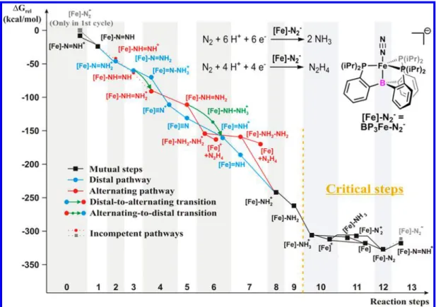
Figure 2.Comparison of the thermodynamics of the possible dinitrogen reduction pathways usingBP3Fe−N2−as catalyst. The horizontal axis shows the total number of particles (H+, e−, and N2) taken up by the transition-metal complex, while the vertical axis represents the Gibbs free energy level relative to the initial state. The nitrogen atoms leave the system in the form of ammonia after disconnection, unless hydrazine formation is specifically noted (“+N2H4”). Solid and dotted lines indicate plausible and improbable elementary reactions, respectively.
Figure 3.Comparison of the thermodynamics of the possible dinitrogen reduction pathways usingSiP3Fe−N2−as catalyst. The horizontal axis shows the total number of particles (H+, e−, and N2) taken up by the transition-metal complex, while the vertical axis represents the Gibbs free energy level relative to the initial state. The nitrogen atoms leave the system in the form of ammonia after disconnection, unless hydrazine formation is specifically noted (“+N2H4”). Solid and dotted lines indicate plausible and improbable elementary reactions, respectively.
Inorganic Chemistry
energetic relations are determined by the energy levels of the thermodynamically most stable spin states.
We also note that our analysis of the catalytic process focuses solely on the thermodynamics. On the basis of the Brønsted−Evans−Polányi principle, however, it can be assumed as a general rule that the energetically most stable intermediate is kinetically also favored among the possible products of each reaction step. A recent DFT study on thefirst protonation steps ofBP3Fe−N2−by de Visser et al.44confirms the validity of this approach: energetically downhill proto- nations on the distal N atom of the catalyst proceed with minimal activation energy (at most 6 kcal/mol), while there is a significant barrier (∼15 kcal/mol) at the thermodynamically unfavorable third protonation, which gives a double-positively charged intermediate. Additionally, very recently Matson and Peters estimated negligible barriers (1−5 kcal/mol) for energetically favorable electron transfers to early intermedi- ates.26
In the following, we present our results regarding the most relevant mechanisms and the location of critical steps in Figures 2and3, where we collate the thermodynamic data of the intermediates likely to be formed from BP3Fe−N2− and SiP3Fe−N2−. All calculated mechanisms can be found in the Supporting Information (Figures S1−S8) together with the detailed description why they are excluded from the present analysis. Furthermore, we compared our computational results with currently available experimental observationsmost relevantly, time-dependent Mössbauer spectra20,21and product characterizations after protonation20,22,23,45
and reduction23of isolated intermediateswhich provided additional information regarding the reactivity of certain intermediates.
For getting relevant results, the ΔGrel data presented here are corrected by adding the amount of Gibbs free energy required for releasing the necessary number of protons and electrons from the acid/reductant. We used diphenylammo- nium ion (acid, ΔGproton release = 259 kcal/mol) and decamethylcobaltocene (reductant, ΔGelectron release = 70 kcal/
mol) as reference systems, because the highest turnover number ever reached with an EPPP scorpionate (BP3Fe−N2−) was observed using these reactants.21InFigures 2 and3, the different pathways are distinguished by colors: mutual intermediates present in all possible mechanisms are shown in black, while the intermediates peculiar to the distal and alternating pathways (Scheme 2) are marked with blue and red color, respectively. Green arrows indicate possible transitions between the main pathways. Dotted lines represent inter- mediate-to-intermediate conversions that are found to be incompetent under the reaction conditions noted (see our discussion below). Numerical data shown inFigures 2 and 3 can be found in the Supporting Information,Table S6.
The catalytic cycle of both EP3Fe−N2− complexes begins with the addition of two protons (Figures 2and3, Steps 1 and 2, as marked on the horizontal axes), forming eitherEP3Fe− NNH2+
(initiating the distal pathway) or the isomeric EP3Fe−NHNH+ (initiating the alternating pathway). Our results indicate thatEP3Fe−NNH2+
is slightly more favored energetically thanEP3Fe−NHNH+ (the difference between ΔGrelvalues is 3 kcal/mol in case E = B and 1 kcal/mol in the case of Si). In addition, the easier steric accessibility of the distal nitrogen atom also tilts the balance in favor of the formation of the distal intermediate. Our findings are in agreement with low-temperature protonation experiments conducted on the initial complex that always give EP3Fe−
NNH2+with no alternating side products.23,45Thus, it can be stated that the distal pathway is initiated in the case of both catalysts, and consequently the formation of diazene gas can be excluded during the catalytic process.
In the next step (Step 3), the positively charged distal intermediate is reduced toEP3Fe−NNH2, which is followed by the addition of the third proton (Step 4). At this point, the reaction either continues to proceed on the distal pathway (formation ofEP3FeN+viaEP3FeN−NH3+ intermediate with a labile N−N bond) or a distal-to-alternating transition occurs, formingEP3Fe−NHNH2+.
In the case of the silicon-containing complexes, the Gibbs free energy profile (Figure 3) suggests the dominance of the alternating pathway, although the distal route is also accessible according to the thermodynamics. Namely, despite the fact that the distal product (SiP3FeN+) is slightly more stable than the alternating intermediate (SiP3Fe−NHNH2+
;ΔG= 7 kcal/mol relative to the nitride), the formation of the former intermediate proceeds throughSiP3FeN−NH3+
, which is 27 kcal/mol higher in energy than SiP3Fe−NHNH2+. Our conclusion that the distal-to-alternating path is superior over the alternative pure distal route is supported by strong experimental evidence: SiP3Fe−NNH2+ can be converted to an alternating intermediate, SiP3Fe−NH2=NH2+
(product of Step 6) in the presence of an electron source.23
Interestingly, the thermodynamic relations observed in Step 4 are significantly altered if boron is present as axial ligand atom instead of silicon (Figure 2). Namely, in contrast to the previously discussed case, the boron-containing nitride (BP3FeN+) is thermodynamically far more stable than BP3Fe−NHNH2+ (Δ(ΔGrel) = 23 kcal/mol). This consid- erable difference, along with the fact that the distal NH2group is more easily accessible for protonation than the proximal nitrogen, suggests that, unlike the previous case, the distal pathway can also be relevant. Here we can infer that probably two routes (distal and distal-to-alternating) are present concurrently, as they are nearly equally favorable. These findings are fully consistent with the available experimental results: protonation ofBP3Fe−NNH2gave the correspond- ing nitride;22nevertheless, formation of hydrazine (released in either Step 6 or Step 7) was detected under certain catalytic conditions.21 Thus, it seems reasonable to assume that experimental observations can be traced back to the presence of two pathways at the same time, the relative abundance of which is a function of the applied proton and electron sources and their concentration. We note that the lack of hydrazine evolution in the case of strong acids and reductants20may well be a result ofN2H4-to-NH3conversion in the reaction mixture.
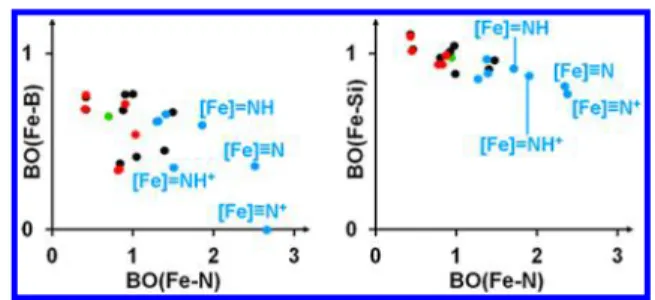
Apart from the thermodynamics, the analysis of bond orders also supports our hypothesis that the distal pathway is more prevalent starting from BP3Fe−N2− than from its silicon analogue. We plot the Fe−E Mayer bond order (MBO) of all intermediates as a function of the Fe−N MBOs in Figure 4 (numerical data can be found in the Supporting Information, Table S6) that provides insight into the special role of the B atom. It is conspicuous at first glance that the data points belonging to the distal intermediates formed in Steps 4−7 (highlighted inFigure 4) stand out from the range covered by the rest of the data points, as they can be characterized by especially high Fe−N MBOs. The crucial difference between the behaviors of the axial ligand bonds in these four structures is remarkable: in contrast to the Fe−Si MBO, which is much less sensitive to the nature of the Fe−N bond, the Fe−B bond Inorganic Chemistry
order in these intermediates shows a drastic decrease with increasing Fe−N MBO (Figure 4, left). The most conspicuous example for this phenomenon isBP3FeN+, in which the Fe− B bond is completely broken (MBO below 0.1). The observed trends indicate that the uniqueflexibility of the Fe−B bond18 has a buffering effect, which damps the variations in the total bond order of the central iron atom. As a result, the distal pathway with E = B is less influenced by electronic reorganizations induced by the partial oxidation/reduction of Fe, which might contribute to the higher TON with E = B compared to E = Si.
Following the branching of the pathways in Step 4, the formed intermediates go through two consecutive reduction− protonation cycles (Figures 2and3, Steps 5 and 6 and Steps 7 and 8) to give a mutual structure,EP3Fe−NH2+, via either the distal or the alternating pathway.
The simplest scenario is the distal route starting from EP3FeN+, as the formation of the new hydrogen atoms from electrons and protons occurs at the only remaining nitrogen atom (EP3FeN+ → EP3FeNH+ → EP3Fe−NH2+
). The Gibbs free energy profile of this reaction sequence shows a constant decrease in the case of both catalysts. Nevertheless, it is a noteworthy difference that the thermodynamic driving force among these elementary steps is more evenly distributed with E = B (ΔG= 19−57 kcal/mol) than with E = Si (ΔG= 13−62 kcal/mol), which is probably related to the previously discussedflexibility of the Fe−B bond.
If the dinitrogen reduction proceeds on the alternating pathway viaEP3Fe−NHNH2+, an electron addition step is followed by the protonation of the proximal nitrogen atom (Step 6), which gives a positively charged hydrazine complex (EP3Fe−NH2−NH2+
). The reduced neutral form of this intermediate is protonated at the distal N atom in Step 8 to give a freeNH3molecule and the mutual intermediateEP3Fe− NH2+. This reaction is referred to as“late-stage”N−N cleavage in the literature,21 as the N−N bond breaks only in Step 8 instead of Step 4. Attempts to locateEP3Fe−NH2−NH3+ on the PES failed, which led us to the conclusion that the addition of H+ and the release of NH3are concerted processes in this step.
Importantly, the elementary reaction steps of the alternating route show a less monotonic behavior than the distal pathway in the Gibbs free energy diagram. This can be traced back to the especially weak driving force in theEP3Fe−NH2−NH2+
to EP3Fe−NH2−NH2conversion (ΔG=−4 kcal/mol with E = B); conspicuously, this process is even uphill (ΔG= +8 kcal/
mol) with E = Si. As a result,SiP3Fe−NH2−NH2+is located in an energy valley (Figure 3), which suggests that, unlike its boron analogue, SiP3Fe−NH2−NH2+ is a long-lived inter- mediate and that its decomposition can be a bottleneck in the catalytic process. Our results also explain whySiP3Fe−NH2− NH2+
appears as the main product in the reaction ofSiP3Fe− N2−with small amounts of acid and reductant.23
Apart from the pure distal or alternating scenarios, several diverted routes need to be considered. First, after the initial reduction to EP3Fe−NHNH2, there is a possibility of an alternating-to-distal transition in Step 6 (formation of the distal intermediateEP3FeNH+ through the release of NH3) that has, to the best of our knowledge, never been mentioned in the literature so far as a possibility. According to our theoretical calculations, this transition is thermodynamically accessible but not favored, because theEP3Fe−NH−NH3+ ions are 17−18 kcal/mol less stable than the respective hydrazine complexes (EP3Fe−NH2−NH2+
).
The second possible diverting reaction is the release of a hydrazine molecule (NH2−NH2) in Step 6 or Step 7. In the case of the boron-containing catalyst, the Gibbs free energy of both decompositions was calculated to be negative (ΔG=−10 kcal/mol in Step 6 and−12 kcal/mol in Step 7); what is more, in the former case the thermodynamic driving force is higher than that of the concurrentBP3Fe−NH2−NH2+ → BP3Fe−
NH2−NH2reduction (ΔG=−4 kcal/mol). Consequently, the cleavage of the Fe−N bond can dominate in the aforemen- tioned reaction steps, and the formation of NH2−NH2 is favored in the catalytic cycle, which is in agreement with recent experimental studies.21As for the analogous processes with E = Si, the thermodynamics suggest dominance of hydrazine formation in Step 6 (ΔG is +8 kcal/mol for reduction and
−2 kcal/mol for Fe−N cleavage), which however proceeds slowly compared to the preceding steps, as the driving force is insignificant.
Thefinal steps of the catalytic cycles are independent of the previous reduction pathways and always go through the same steps (Figures 2 and 3). In case hydrazine is not released, EP3Fe−NH2+ is formed in Step 8 and later EP3Fe−NH3+ through a reduction and a protonation in Steps 9 and 10. The formation of the positively charged ammonia complex in Step 10 is thermodynamically highly favorable, which is however disadvantageous in this stage of the catalytic cycle, because EP3Fe−NH3+ becomes as stable as the regenerated catalyst.
After Step 13,ΔGrelof both EP3Fe−N2− complexes is−313 kcal/mol, which corresponds to the Gibbs free energy change in the reaction of N2+ 6H+ + 6e−→2NH3. By comparison, the relative Gibbs free energies ofBP3Fe−NH3+
andSiP3Fe− NH3+
were calculated to be −309 and −317 kcal/mol, respectively. This means that the thermodynamic driving force is almost fully consumed as many as three reaction steps before the end of the catalytic cycle. As a result, Steps 11−13 probably proceed slowly relative to the previous reaction steps and present the critical steps of the reaction mechanism. In addition, according to the Brønsted−Evans−Polányi principle, the thermodynamically nearly neutral or uphill protonation and reduction processes probably also suggest activation barriers larger than those of the analogous previous steps.
Moreover, it should not escape our attention that inter- mediates with longer lifetime are more susceptible for other side reactions that might also lead to deactivation not just sluggish reactivity.
Figure 4. MBO of Fe−B and Fe−Si bonds present in the intermediates shown in Figure 2 and Figure 3, respectively, as a function of the Fe−N bond order. The coloring of the data points corresponds to the colors used to distinguish the pathways inFigures 2 and 3 (blue: distal, red: alternating, black: mutual, green:
transition). Highlighted are the distal intermediates formed in Steps 4−7.
Inorganic Chemistry
Steps 11 and 12 involve reduction, coordination of an N2 molecule, and cleavage of the Fe−N bond to form the neutral intermediate EP3Fe−N2. The sequence of these three reactions may vary as the intermediates EP3Fe, EP3Fe+, EP3Fe−NH3, and EP3Fe−N2+
are so close in Gibbs free energy that in most cases even the order of their stability is questionable considering the error of DFT. What is more, various other factors (difference in the rate of unimolecular and bimolecular reactions, concentration of N2, etc.) are capable of influencing the dominant pathway.
To fully close the catalytic cycle, thefinal step would be the regeneration of the catalyst through a reduction step; however, it appears that the protonation of the neutral intermediate is thermodynamically more favorable. The regenerated catalyst is 4 kcal/mol less stable than the positively charged intermediate in the case of BP3Fe−N2−, while the corresponding silicon- containing analogues differ by 15 kcal/mol inΔGrel. Still, the change of protonation Gibbs free energy in Step 13 is positive in the case of both catalysts.ΔG of the last proton addition step, formation ofBP3FeNNH+ andSiP3FeNNH+, is +10 and +5 kcal/mol, respectively. Consequently, after the first cycle in the catalytic process, the negatively charged dinitrogen complexes expectedly disappear from the catalytic mixtures.
The calculated too early consumption of the thermodynamic driving force, observed as the flattening of the Gibbs free energy profiles (critical steps inFigures 2and3), the presence of an unfavorable energy valley (EP3Fe−N2) in thefinal steps, and the lack of the regeneration of the initial catalyst are also supported by the available experimental data. Namely, freeze- quench Mössbauer spectra taken with the boron-containing catalyst21indicate that most Fe atoms in the catalytic mixture are in the form ofBP3Fe−N2after 30 min of incubation, and a significant amount of BP3Fe+ was also detected. Apart from these intermediates, only two unidentified, likely off-path, Fe complexes were perceived to be present in the sample. The observation of BP3Fe−N2 and BP3Fe+ justifies their long lifetime and stability, which can be traced back to the lack of thermodynamic driving force at thefinal stage of the catalytic cycle. Even though theΔGrelof BP3Fe+ is not outstandingly low among the last intermediates, its formation is also facilitated by the displacement of the coordinated NH3 by a solvent molecule, which exchange reaction was reported to occur spontaneously in the case of the Si analogue.46In the same experiment, it was also shown thatBP3Fe−N2−gradually disappears, which proves the dominance of protonation in Step 13. Important to note that other, stronger reductant might change the potential energy landscape and that BP3Fe−N2− can be favored over BP3FeNNH+ because of the small energy difference. Experimental results suggest that this is the situation for KC8, in which caseBP3Fe−N2−was observed.20 It is interesting to compare the obtained full Gibbs free energy profile of the Peters system to that of Schrock’s and Nishibayashi’s molybdenum-based catalysts,6−13 which were reported in previous DFT studies.47−49 Remarkably, the triamidoamine-ligated Mo center (Scheme 1, top left) shows similar behavior to the scorpionate complexes studied herein:
at the final stage of dinitrogen reduction, starting from the formation of Mo−NH3+
(the Schrock-type analogue of EP3Fe−NH3+), endergonic and nearly thermoneutral steps appear, and all the thermodynamic driving force is consumed in the previous elementary reactions similar to our results.47 What is more, the protonation of the neutral N2-coordinated
complex was found to be endergonic even for the bimetallic Nishibayashi system (Scheme 1, bottom middle, R = H),48 wherein contrast to the former two systemsthe thermodynamic relations during the catalytic process are largely determined by the electronic interactions between the transition-metal centers.49 Our findings suggest that the thermodynamically unfavorable N2 protonation and the outstanding stability of the intermediates in the final phase might be general in homogeneous dinitrogen reduction systems.
As we managed to determine the competent catalytic mechanisms and obtain their complete Gibbs free energy profile, now it becomes possible to locate the critical steps that the rational catalyst design should focus on. This can be done on the basis of the Sabatier principle, which states in general that the interactions between the catalyst and the substrate should be neither too weak (so that the catalytic complex is easily formed) nor too strong (so that the product is easily released).50In our case, the Sabatier principle combined with the Brønsted−Evans−Polanyi principle requires that, foŕ optimal catalytic performance, the Gibbs free energy of the intermediates should follow a nearly linearly descending trend that has been proved in several cases.51−53 Deviation from linearity by finding “edges” in the Gibbs free energy profile, which appear due to a considerable difference between the thermodynamics of the formation of a given intermediate and that of the subsequent elementary steps, means that the intermediate is more stable (“too strong interactions”) or less stable (“too weak interactions”) than desired and that the product formation is hindered. The evaluation of the shape of the Gibbs free energy profile using this approach has already been successfully applied in studies on electrochemical N2 reduction, to demonstrate the inevitability of a sufficient minimal overpotential due to the unfavorable thermodynamic relations of the key intermediates.54
According to our computational results, the last steps starting fromEP3Fe−NH3+can be considered as critical steps, because the steepness of the Gibbs free energy profile is reduced to nearly zero in this range and can be one reason for the low catalytic turnover numbers. Experimental results also indicate the longer lifetime of the last intermediates, as they were successfully characterized spectroscopically. This unfav- orable resting of the reaction sequence also opens the possibility of catalyst degradation through concurrent side reactions, for example, by the protonation of the iron center,19,55resulting in the formation of hydrides that can be potential sources of HER. Apart from this final stage of the catalytic cycle, theSiP3Fe−NH2−NH2+intermediate is located in an energy valley that adds an additional critical step in the nitrogen reduction using the silicon-containing catalyst.
Therefore, the observed energy valley atSiP3Fe−NH2−NH2+
and the presumable dominance of the distal-to-alternating transition over the distal route in Step 4 can also provide an explanation for the decreased TON ofSiP3Fe−N2−relative to its boron analogue.
On the basis of the Sabatier principle and our results, the key for gaining more efficient catalysts than the currently best BP3Fe−N2−is the destabilization of the intermediates in Steps 10−12, which would result in a nearly even distribution of the thermodynamic driving force among N2-coordination, reduc- tion, and product release steps. This can be, for example, achieved by properly redesigning the catalyst ligand field, which can be easily done using computational techniques, by Inorganic Chemistry
screening the modified ligands according to the relative Gibbs free energies of thefinal intermediates.
Finally, we note that our computational model presented in this paper does not take reagent-specific effects into account, as our aim was to draw general conclusions regarding the critical steps of biomimetic catalysts. When studying dinitrogen reduction under well-defined circumstances (acid, reductant, solvent, etc.), several distinctive factors are capable of modifying the picture.
First, elementary steps involving spin changes might be influenced by structural and reorganization effects, the extent of which can depend on the reductant and solvent applied.
Nevertheless, the activation energies deriving from reorganiza- tions were found to be negligible with KC8,26and experimental works performed with other electron sources do not suggest any difference that would indicate that spin change in thermodynamically downhill reaction steps can be rate- determining. Second, proton-coupled electron transfer (PCET) pathways might become accessible using certain acid-reductant combinations. For instance, diphenylammo- nium salts and decamethylcobaltocene are reported to form a reactive PCET reagent, (Cp*CoC5Me5H)+,21 the hydrogen atom transfer from which might circumvent thermodynami- cally uphill steps. To examine the role of this alternative scenario, we calculated the Gibbs free energy of theEP3Fe−N2
→EP3Fe−NNH transition by PCET. We found that this reaction is endergonic (ΔG= +6 kcal/mol) for both systems, though in case of E = B it is favored over the concurrent proton transfer to the distal N atom (ΔG = +10 kcal/mol) according to thermodynamics. Additionally, PCET toEP3Fe− NH2−NH2+(E = B:ΔG=−75 kcal/mol, E = Si:ΔG=−76 kcal/mol) provides a highly favorable alternative for the reduction toEP3Fe−NH2−NH2(E = B:ΔG=−4 kcal/mol, E
= Si:ΔG= +8 kcal/mol), which means that even the critical valley shown onFigure 3can be circumvented. The presence of these PCET-mediated routes likely contributes to the outstandingly high turnover numbers reached with dipheny- lammonium ion as acid and decamethylcobaltocene as reductant.
■
CONCLUSIONSIn this computational study, we determined the Gibbs free energy profile of the catalytic cycle of dinitrogen reduction to NH3catalyzed by the artificial nitrogenasesEP3Fe−N2−(E = B, Si). We identified the dominant reaction mechanisms and the critical reaction steps, which is indispensable for future rational design of novel, effective biomimetic catalysts.
In the case of the high-performing boron-containing catalyst, the reduction proceeds via two concurrent pathways: the distal route (BP3Fe−N2− → BP3Fe−NNH2+ → BP3FeN+→ BP3Fe−NH3+
) and the distal-to-alternating route (BP3Fe− N2−→BP3Fe−NNH2+→BP3Fe−NH2−NH2+→BP3Fe− NH3+
), the latter of which can also result in hydrazine release fromBP3Fe−NH2−NH2+or its neutral form. The substitution of the auxiliary ligand atom to silicon does not affect the mechanisms themselves, but the low-performing silicon- containing catalyst tends to favor the distal-to-alternating route (SiP3Fe−N2− →SiP3Fe−NNH2+ →SiP3Fe−NH2− NH2+
) over the distal pathway. Remarkably, the former mechanism requires a PCET step to circumvent the unfavorable energy valley at the intermediateSiP3Fe−NH2− NH2+, while the latter route proceeds with evenly descending Gibbs free energy. The catalytic process with E = Si most likely
leads to Fe−N cleavage and the formation of hydrazine, which can be partly or fully reduced toNH3in the catalytic mixture, depending on the circumstances.
Our results also reveal that there is negligible thermody- namic driving force in the last three steps of the catalytic cycle (Steps 11−13: EP3Fe−NH3+ →EP3Fe−N2 →EP3FeN NH+), and they can be considered as a bottleneck of the catalytic cycle, because these critical steps involve thermody- namically nearly neutral or even uphill processes. In addition, according to the Brønsted−Evans−Polányi principle, larger activation barriers are postulated than that in the previous steps that also correspond to slower catalytic reaction.
Intermediates formed in this phase are also susceptible for side reactions; therefore, it is a reasonable assumption that destabilizing EP3Fe−NH3+ and the intermediates formed in the subsequent steps can be one key factor to enhance the catalytic activity. Rational design of future biomimetic catalysts should focus on destabilizing these critical steps to evenly distribute the thermodynamic driving force among the 13 elementary steps of the catalytic cycle according to the Sabatier principle. As previous DFT studies on Mo-based catalysts point to the existence of critical steps in the same phase of the catalytic cycle as reported herein, the described rational design strategy might be generally applicable for homogeneous dinitrogen reduction systems.
■
ASSOCIATED CONTENT*S Supporting Information
The Supporting Information is available free of charge on the ACS Publications website at DOI: 10.1021/acs.inorg- chem.8b01183.
Description and results of the test calculations used for selecting the theoretical method, details of the calculation of Gibbs free energy profiles, optimized geometries of all intermediates (PDF)
■
AUTHOR INFORMATION Corresponding Authors*E-mail:julianna.olah@mail.bme.hu. (J.O.)
*E-mail:szilvasi@wisc.edu. (T.S.) ORCID
Tibor Szilvási:0000-0002-4218-1570 Notes
The authors declare no competingfinancial interest.
■
ACKNOWLEDGMENTSWe are grateful for generous support of The New Szechenyí Plan TAMOP-4.2.2/B-10/1-2010-0009. Z.B. thanks the support of the New National Excellence Program of the Ministry of Human Capacities of Hungary. J.O. is also thankful for thefinancial support of NKFIH Grant No. 115503 and of a Bolyai János Research Fellowship.
■
(1)REFERENCESMineral Commodity Summaries 2017; U. S. Geological Survey:Reston, VA, 2017.
(2) Jewess, M.; Crabtree, R. H. Electrocatalytic Nitrogen Fixation for Distributed Fertilizer Production?ACS Sustainable Chem. Eng.2016, 4, 5855−5858.
(3) Renner, J. N.; Greenlee, L. F.; Herring, A. M.; Ayres, K. E.
Electrochemical Synthesis of Ammonia: A Low Pressure, Low Temperature Approach.Electrochem. Soc. Interface2015,24, 51−57.
Inorganic Chemistry
(4) Nitrogen Fixation, 3rd ed.; Postgate, J., Ed.; Cambridge University Press: Cambridge, England, 1998.
(5) Stucke, N.; Flöser, B. M.; Weyrich, T.; Tuczek, F. Nitrogen Fixation Catalyzed by Transition Metal Complexes: Recent Develop- ments.Eur. J. Inorg. Chem.2018,2018, 1337. and references therein.
(6) Yandulov, D. V.; Schrock, R. R. Catalytic reduction of dinitrogen to ammonia at a single molybdenum center.Science2003,301, 76−
78.
(7) Schrock, R. R. Catalytic reduction of dinitrogen to ammonia by molybdenum: theory versus experiment.Angew. Chem., Int. Ed.2008, 47, 5512−5522.
(8) Arashiba, K.; Miyake, Y.; Nishibayashi, Y. A molybdenum complex bearing PNP-type pincer ligands leads to the catalytic reduction of dinitrogen into ammonia.Nat. Chem.2011,3, 120−125.
(9) Tanaka, H.; Arashiba, K.; Kuriyama, S.; Sasada, A.; Nakajima, K.;
Yoshizawa, K.; Nishibayashi, Y. Unique behaviour of dinitrogen- bridged dimolybdenum complexes bearing pincer ligand towards catalytic formation of ammonia.Nat. Commun.2014,5, 3737.
(10) Kuriyama, S.; Arashiba, K.; Nakajima, K.; Tanaka, H.; Kamaru, N.; Yoshizawa, K.; Nishibayashi, Y. Catalytic Formation of Ammonia from Molecular Dinitrogen by Use of Dinitrogen-Bridged Dimolyb- denum−Dinitrogen Complexes Bearing PNP-Pincer Ligands: Re- markable Effect of Substituent at PNP-Pincer Ligand.J. Am. Chem.
Soc.2014,136, 9719−9731.
(11) Arashiba, K.; Kinoshita, E.; Kuriyama, S.; Eizawa, A.; Nakajima, K.; Tanaka, H.; Yoshizawa, K.; Nishibayashi, Y. Catalytic Reduction of Dinitrogen to Ammonia by Use of Molybdenum−Nitride Complexes Bearing a Tridentate Triphosphine as Catalysts. J. Am. Chem. Soc.
2015,137, 5666−5669.
(12) Eizawa, A.; Arashiba, K.; Tanaka, H.; Kuriyama, S.; Matsuo, Y.;
Nakajima, K.; Yoshizawa, K.; Nishibayashi, Y. Remarkable catalytic activity of dinitrogen-bridged dimolybdenum complexes bearing NHC-based PCP-pincer ligands toward nitrogen fixation. Nat.
Commun.2017,8, 14874.
(13) Tanaka, H.; Nishibayashi, Y.; Yoshizawa, K. Interplay between Theory and Experiment for Ammonia Synthesis Catalyzed by Transition Metal Complexes.Acc. Chem. Res.2016,49, 987−995.
(14) Seefeldt, L. C.; Hoffmann, B. M.; Dean, D. R. Mechanism of Mo-dependent nitrogenase.Annu. Rev. Biochem.2009,78, 701−722.
(15) Hoffman, B. M.; Lukoyanov, D.; Yang, Z.-Y.; Dean, D. R.;
Seefeldt, L. C. Mechanism of Nitrogen Fixation by Nitrogenase: The Next Stage.Chem. Rev.2014,114, 4041−4062.
(16) Lukoyanov, D.; Khadka, N.; Yang, Z.-Y.; Dean, D. R.; Seefeldt, L. C.; Hoffman, B. M. Reductive Elimination of H2 Activates Nitrogenase to Reduce the N≡N Triple Bond: Characterization of the E4(4H) Janus Intermediate in Wild-Type Enzyme.J. Am. Chem. Soc.
2016,138, 10674−10683.
(17) Kuriyama, S.; Arashiba, K.; Nakajima, K.; Matsuo, Y.; Tanaka, H.; Ishii, K.; Yoshizawa, K.; Nishibayashi, Y. Catalytic transformation of dinitrogen into ammonia and hydrazine by iron-dinitrogen complexes bearing pincer ligand.Nat. Commun.2016,7, 12181.
(18) Anderson, J. S.; Rittle, J.; Peters, J. C. Catalytic conversion of nitrogen to ammonia by an iron model complex.Nature2013,501, 84−87.
(19) Creutz, S. E.; Peters, J. C. Catalytic Reduction of N2to NH3by an Fe−N2Complex Featuring a C-Atom Anchor.J. Am. Chem. Soc.
2014,136, 1105−1115.
(20) Del Castillo, T. J.; Thompson, N. B.; Peters, J. C. A Synthetic Single-Site Fe Nitrogenase: High Turnover, Freeze-Quench 57Fe Mössbauer Data, and a Hydride Resting State.J. Am. Chem. Soc.2016, 138, 5341−5350.
(21) Chalkley, M. J.; Del Castillo, T. J.; Matson, B. D.; Roddy, J. P.;
Peters, J. C. Catalytic N2-to-NH3Conversion by Fe at Lower Driving Force: A Proposed Role for Metallocene-Mediated PCET.ACS Cent.
Sci.2017,3, 217−223.
(22) Thompson, N. B.; Green, M. T.; Peters, J. C. Nitrogen Fixation via a Terminal Fe(IV) Nitride.J. Am. Chem. Soc.2017,139, 15312− 15315.
(23) Rittle, J.; Peters, J. C. An Fe-N2 Complex That Generates Hydrazine and Ammonia via FeNNH2: Demonstrating a Hybrid Distal-to-Alternating Pathway for N2 Reduction. J. Am. Chem. Soc.
2016,138, 4243−4248.
(24) Silantyev, G. A.; Förster, M.; Schluschaß, B.; Abbenseth, J.;
Würtele, C.; Volkmann, C.; Holthausen, M. C.; Schneider, S.
Dinitrogen Splitting Coupled to Protonation.Angew. Chem., Int. Ed.
2017,56, 5872−5876.
(25) Husch, T.; Reiher, M. Mechanistic Consequences of Chelate Ligand Stabilization on Nitrogen Fixation by Yandulov−Schrock- Type Complexes.ACS Sustainable Chem. Eng.2017,5, 10527−10537.
(26) Matson, B. D.; Peters, J. C. Fe-Mediated HER vs N2RR:
Exploring Factors That Contribute to Selectivity in P3EFe(N2) (E = B, Si, C) Catalyst Model Systems.ACS Catal.2018,8, 1448−1455.
(27) Reiher, M.; Le Guennic, B.; Kirchner, B. Theoretical Study of Catalytic Dinitrogen Reduction under Mild Conditions.Inorg. Chem.
2005,44, 9640−9642.
(28) Studt, F.; Tuczek, F. Energetics and Mechanism of a Room- Temperature Catalytic Process for Ammonia Synthesis (Schrock Cycle): Comparison with Biological Nitrogen Fixation.Angew. Chem., Int. Ed.2005,44, 5639−5642.
(29) Studt, F.; Tuczek, F. Theoretical, spectroscopic, and mechanistic studies on transition-metal dinitrogen complexes:
Implications to reactivity and relevance to the nitrogenase problem.
J. Comput. Chem.2006,27, 1278−1291.
(30) Gogoi, U.; Guha, A. K.; Phukan, A. K. Tracing the Route to Ammonia: A Theoretical Study on the Possible Pathways for Dinitrogen Reduction with Tripodal Iron Complexes. Chem. - Eur.
J.2013,19, 11077−11089.
(31) Neese, F. Software update: the ORCA program system, version 4.0.WIREs Comput. Mol. Sci.2018,8, 1.
(32) Becke, A. D. Density-functional exchange-energy approxima- tion with correct asymptotic behavior.Phys. Rev. A: At., Mol., Opt.
Phys.1988,38, 3098.
(33) Perdew, J. P. Density-functional approximation for the correlation energy of the inhomogeneous electron gas.Phys. Rev. B:
Condens. Matter Mater. Phys.1986,33, 8822.
(34) Weigend, F.; Ahlrichs, R. Balanced basis sets of split valence, triple zeta valence and quadruple zeta valence quality for H to Rn:
Design and assessment of accuracy.Phys. Chem. Chem. Phys.2005,7, 3297−3305.
(35) Stephens, P. J.; Devlin, F. J.; Chabalowski, C. F.; Frisch, M. J.
Ab Initio Calculation of Vibrational Absorption and Circular Dichroism Spectra Using Density Functional Force Fields. J. Phys.
Chem.1994,98, 11623−11627.
(36) van Wüllen, C. Molecular density functional calculations in the regular relativistic approximation: Method, application to coinage metal diatomics, hydrides, fluorides and chlorides, and comparison with first-order relativistic calculations. J. Chem. Phys. 1998, 109, 392−399.
(37) Grimme, S.; Ehrlich, S.; Goerigk, L. Effect of the damping function in dispersion corrected density functional theory.J. Comput.
Chem.2011,32, 1456−1465.
(38) Grimme, S.; Antony, J.; Ehrlich, S.; Krieg, H. A consistent and accurate ab initio parametrization of density functional dispersion correction (DFT-D) for the 94 elements H-Pu.J. Chem. Phys.2010, 132, 154104.
(39) Barone, V.; Cossi, M. Quantum Calculation of Molecular Energies and Energy Gradients in Solution by a Conductor Solvent Model.J. Phys. Chem. A1998,102, 1995−2001.
(40) Neese, F.; Wennmohs, F.; Hansen, A.; Becker, U. Efficient, approximate and parallel Hartree-Fock and hybrid DFT calculations.
A‘chain-of-spheres’algorithm for the Hartree-Fock exchange.Chem.
Phys.2009,356, 98−109.
(41) Weigend, F. Accurate Coulomb-fitting basis sets for H to Rn.
Phys. Chem. Chem. Phys.2006,8, 1057−1065.
(42) Ashcraft, R. W.; Raman, S.; Green, W. H. Ab initio aqueous thermochemistry: Application to the oxidation of hydroxylamine in nitric acid solution.J. Phys. Chem. B2007,111, 11968−11983.
Inorganic Chemistry