Vacuum 192 (2021) 110415
Available online 27 June 2021
0042-207X/© 2021 The Authors. Published by Elsevier Ltd. This is an open access article under the CC BY-NC-ND license
(http://creativecommons.org/licenses/by-nc-nd/4.0/).
Ammonia-vapour-induced two-layer transformation of mesoporous silica coatings on various substrates
Lenke K ocs ´
a, Borb ´ ala Tegze
a, Em ˝ oke Albert
a, Csaba Major
b, Andr ´ as Szalai
b, B ´ alint Fodor
c, P ´ eter Basa
c, Gy orgy S ¨ ´ afr ´ an
d, Zolt ´ an H ´ orv ¨ olgyi
a,*aDepartment of Physical Chemistry and Materials Science, Centre for Colloid Chemistry, Faculty of Chemical Technology and Biotechnology, Budapest University of Technology and Economics, H-1521, Budapest, Budafoki út 6–8, Hungary
bHungaro Lux Light Ltd., H-2142 Nagytarcsa, Asb´oth Oszkar utca 7. B/4, Hungary ´
cSemilab Semiconductor Physics Laboratory Co. Ltd, H-1117, Budapest, Prielle Korn´elia Str. 2, Hungary
dInstitute of Technical Physics and Materials Science, Centre for Energy Research, Konkoly Thege M. út 29–33, H-1121, Budapest, Hungary
A R T I C L E I N F O Keywords:
Silica coating
Pseudomorphic transformation Mesoporous
Anti-reflective coatings Ammonia vapour treatment
A B S T R A C T
We prepared mesoporous silica layers by sol-gel dip-coating technique on various substrates (silicon, poly- carbonate, microscope glass and quartz) with the aid of a pore-forming triblock copolymer (Pluronic PE10500).
The freshly deposited layers were aged in an aqueous ammonia solution atmosphere. Two types of thermal curing were implemented depending on the substrates: a low-temperature heat treatment at 120 ◦C for 13 hours or a high-temperature heat treatment at 480 ◦C for 1 hour. We carried out the porogen extraction of the copolymer molecules from the low-temperature heat-treated samples in a water washing step.
Optical spectroscopy measurements gave evidence of a significantly improved and long-lasting light trans- mission of coatings. The maximum light transmission was 98.3% on glass and 97.6% on polycarbonate after 4 years of storage. TEM investigations showed thin layers with distorted face centred cubic structure.
Spectroscopic ellipsometry and ellipsometric porosimetry studies showed a “two-layer” structure. The applied synthesis technique promoted the formation of a double layer structure with relatively thick (10–25 nm) pore sizes. The pseudomorphic transformation rearranged the silica/copolymer structure in presence of ammonia. The transformation was incomplete and resulted in a low porosity (23–34%) upper-layer and a high porosity (40–76%) lower-layer.
1. Introduction
Silica coatings with low reflective index and mesoporous structure have a rising interest in a variety of applications, such as molecular filtration [1], sensors [2] or nano theranostics purposes [3].
Anti-reflective coatings on polymers are particularly useful as protective covers of street lightning LED fixtures [4,5] or automobile displays [6].
The functional coating contributes to reduced carbon dioxide emissions and lower power consumption, as well as to increased performance. The high transmission can be combined with hydrophobic, photocatalytic or anti-fogging properties [7,8] in case of outdoor uses to increase the ef- ficiency. Despite the widespread investigation of mesoporous silica thin films, there is considerable potential for new structures and applications.
Due to the polar character and large surface area of the mesoporous silica thin films, they are even more exposed to environmental contamination. The surface of silica coatings is often post-treated, or the precursor sol is supplemented by hydrophobic silica reagent during the synthesis to avoid performance degradation. The most accepted method is the use of methyl groups containing silica precursors [9,10], which can ensure water repellence and hence, the self-cleaning properties of coatings. There are other techniques to maintain the high light trans- mission without additional silica reagents, for examples the ammonia vapour treatment of thin films [4].
The porous structure can be redesigned to obtain improved proper- ties and possibilities for new applications [11]. François Fajula’ research group first introduced the concept of pseudomorphic synthesis in 2002.
* Corresponding author. Budapest University of Technology and Economics; Budafoki út 6–8, H-1521, Budapest, Hungary.
E-mail addresses: lenke.kocs@edu.bme.hu (L. Kocs), tegze.borbala@vbk.bme.hu (B. Tegze), albert.emoke@vbk.bme.hu (E. Albert), dr.major.csaba77@gmail.com ´ (C. Major), szalai.andras@hungarolux.hu (A. Szalai), balint.fodor@semilab.hu (B. Fodor), peter.basa@semilab.hu (P. Basa), safran.gyorgy@energia.mta.hu (G. S´afr´an), horvolgyi.zoltan@vbk.bme.hu (Z. H´orv¨olgyi).
Contents lists available at ScienceDirect
Vacuum
journal homepage: www.elsevier.com/locate/vacuum
https://doi.org/10.1016/j.vacuum.2021.110415
Received 1 March 2021; Received in revised form 14 June 2021; Accepted 24 June 2021
During the synthesis, the amorphous silica nanoparticle is converted into an ordered mesoporous structure [12,13]. The two main compo- nents that induced the morphological changes are the alkaline medium (NaOH aqueous solution) and the presence of a structure-directing agent (CTAB surfactant). They have studied and reported the process of self-assembly in particles and monoliths [14], but not on thin films.
Grosso et al. investigated the influence of the ammonia vapour treat- ment on anti-reflective sol-gel coatings. They concluded that for an optimal rearrangement of silica units in the presence of surfactant (F127 Pluronic), at least 1 hour in an atmosphere of 28% ammonium hy- droxide solution is recommended. The Ostwald-ripening-driven struc- tural modification increases the porous volume [15]. Xing and Rankin observed a pore expansion of the ordered mesoporous silica material induced by the ammonia post-treatment and a mixture of surfactants [16].
The literature presents different pathways to have control over the morphology during the synthesis. The preparation of silica nanospheres needs various strategies, especially of the mesoporous sphere, hollow sphere, core-shell sphere or yolk-shell sphere structure [17]. One of the specific features of nanoparticles is the bimodal porous arrangement having two distinct areas with different pore size. These structures can be obtained through a pseudomorphic transformation process in which an existing pore system is reorganised so that the original particle size and shape remain intact [12–14,18]. In some cases, the two porous domains are interconnected with bottleneck pores [19,20]. The driving force of the formation of a bimodal porous system depends on the applied starting materials, and a structure-directing agent is required [21]. Among the reported bimodal silica systems can be found modified SBA–15 with micropores connected to large mesopores (micro–meso) [22], mesopores with similar pore sizes (meso–meso) [23], or hierar- chical mesoporous and macroporous silica monoliths (macro–meso) [24]. Sol–gel silica thin films are often strengthened in an ammonia atmosphere to increase the cross-linkage of silica networks and improve the mechanical properties [25–27] and stability [4].
We report on a comprehensive examination of sample preparation, characterisation, and evaluation of silica sol-gel coatings. We found that the double layer formation occurs in all substrates and at all heat treatments and layer deposition speed. This paper presents a one-pot synthesis of a double-layer anti-reflective coating prepared with a sin- gle deposition step. The structure-directing agent used in this study is a non-ionic Pluronic surfactant. The secondary synthesis of the as- deposited layers was facilitated during ammonia vapour treatment.
2. Materials and methods 2.1. Materials
All chemicals were used without further purification. Silica precursor sol was synthesised from 3.7 ml tetraethyl orthosilicate (TEOS, 98%, Acros Organics), 33 ml 2-propanol (2-PrOH, a. r., 99.7%, Reanal), and 3 ml 0.1 M hydrochloric acid (HCl, ACS Reagent, 37%, Honeywell Fluka).
2.26 g Pluronic PE10500 triblock copolymer (research sample from BASF, 100%) was added to form the pore system. The mixture was stirred for 2 hours at room temperature.
The coated solid substrates were microscope glass (G, 76 ×26 ×1 mm, Thermo Scientific, soda-lime glass), quartz (Q, 40 ×30 ×1 mm, Suprasil®), polycarbonate (P, 50 ×25 ×2.1 mm LEXAN™, XL102UV Sheet) and silicon (S, 40 × 30 × 1 mm, Double Side Polished, 100, Siegert Wafer GmbH).
2.2. Sample preparation
The silica sol was deposited on various substrates with a dip coater (Plosz M´ ´ern¨okiroda Kft., Hungary). The withdrawal speed was in the intermediate regime, between 0.1 and 1 mm ⋅ s−1 [28,29]. At least 3 parallel samples were prepared. The samples were placed in a desiccator
above an aqueous ammonium hydroxide solution (2 M) at room tem- perature (23–26 ◦C) for 1 hour or 3 hours [4]. The volume of the desiccator was 11 L. After that, two types of thermal curing were implemented: low-temperature heat treatment at 120 ◦C for 13 hours or high-temperature heat treatment at 480 ◦C for 1 hour. Water washing or calcination was involved to remove the surfactant micelles from the interior of the silica matrix. The water dissolved the surfactant micelles and additionally removed the polar by-products after the thermal treatment. This solvent extraction was a pore cleaning step; therefore, it was applied for all the samples regardless of the cure temperature. It is possible that the water washing did not completely remove the Pluronic PE10500 molecules from the low-temperature heat-treated samples. In our experiment, we used thin layers (d <260 nm) and we soaked the samples in water for 30 minutes under constant stirring at room tem- perature to result in an effective porogen extraction (see Supporting Information).
We introduced a sample annotation to provide information about the experimental conditions. The first letter stands for the type of substrate (G - glass, P - polycarbonate, S - silicon or Q - quartz). The second part is the value of the withdrawal speed, expressed in cm ⋅ min−1 (1.0–4.5).
The third part of the code is the duration of the ammonia vapour treatment in hours (1 or 3). The last letter indicates the value of the curing temperature in Celsius (medium (M) for 120 ◦C and high (H) for 480 ◦C). For example, code G1.5-1M refers to a sample on the glass substrate (G), where the layer deposition speed was 1.5 cm ⋅ min−1 (1.5), the ammonia vapour treatment was 1 hour (1), and the thermal curing was 120 ◦C (M).
2.3. Characterisation
The optical quality and shelf-life of the transparent samples were followed up by recording their transmission spectra between 350 and 1000 nm with 1 nm resolution and 5 nm ⋅ s−1 scanning speed at normal incidence (Analytic Jena Specord 200–0318 UV–Vis spectrophotom- eter). The relative humidity during the measurement varied between 30% and 40%. We calculated the layer thickness, refractive index, and porosity of samples on PC and glass with the Hild model [30]. It uses the geometric optical solution for double-sided deposited coatings on a transparent thick substrate. The Hild model presumes that the layer is monolayer because the model cannot separate layers with similar refractive indices. As a result, we have estimated the total layer thick- ness, the average refractive index and the average porosity of the coat- ings. The fitting procedure uses the Levenberg–Marquardt algorithm [31]. The porosity of the coatings was estimated from the refractive index using the Lorentz–Lorenz formula [32–34]. We set the refractive index of glass to 1.519, the polycarbonate to 1.585, and the non-porous silica layer to 1.462 as the reference bulk material.
All samples were analysed by spectroscopic ellipsometry over the spectral range of 350–1000 nm. In the ISO 17025 accredited laboratory, the temperature was between 20 ◦C and 25 ◦C and the relative humidity was between 40% and 45%. The layer thickness, refractive index and porosity of the samples were determined by fitting an optical model calculated spectra to the measured spectra. The complex refractive indices of the applied substrates have been preliminarily determined from bulk measurements with the Cauchy dispersion model and the Cauchy parameters were fixed during subsequent evaluations. To eval- uate the porous sample measurements, a Brugemann effective medium approximation (EMA) based model was created. The porous silica structure was optically described with a double-layer EMA model composed of SiO2 and Void, where the Void ratios of both the upper and lower effective layers were fitted independently (referred to as porosity in the table values). The ellipsometric models had the following struc- ture: the substrate (polycarbonate, glass, and c-Si); the lower layer (EMA1: VOID 1 (%), thickness 1 (nm), SiO2 +Void); and the upper layer (EMA2: VOID 2 (%), thickness 2 (nm), SiO2 +Void).
The porosity, refractive index, layer thickness, and pore size
distribution of the silica samples were also determined with ellipsometric-porosimetry using a Semilab’s PS-2000 instrument. All silica samples were outgassed at 140–150 ◦C for 10 min before analysis.
This short and extra heating might have affected the thickness and porosity of samples cured at 120 ◦C. The adsorptive material was toluene and 2-propanol. The refractive index of the substrate at 632.8 nm was specified from reference values: 3.881 for silicon, 1.5151 for glass, 1.457 for quartz and 1.580 for PC [35]. The layer thickness and the effective refractive index of the coatings were determined with the Cauchy model. The pore radius distribution (rad, rdes) was calculated with the modified Kelvin model for mesopores. The adsorption and desorption isotherms were taken at 30 ◦C in a vacuum chamber.
Top-view and cross-sectional image of the silica layers on Si were recorded with a LEO 1540 XB field emission scanning electron micro- scope (FE-SEM). Plan view and cross-sectional samples for HRTEM were prepared with the conventional mechanical and Ar-ion beam thinning techniques [36]. High-resolution transmission electron microscopy (HRTEM) investigations were carried out with a JEOL 3010 instrument operated at 300 kV, with a point resolution of 0.17 nm.
Specific conditions for carrying out the water solubility of an optical coating and the effect of the humidity on its optical properties are described in ISO 9211 standards (Optics and photonics — Environ- mental test methods — Part 2: Cold, heat and humidity (ISO 9022–2:2015) [37] and Part 4: Specific test methods (ISO 9211–4:2012) [38]. We performed the solubility test and the damp heat test on samples P1.0–3M according to the ISO standards. The water solubility test was carried out in a laboratory environment. The samples were soaked in distilled water at room temperature for 6 h. Damp heat test required an environmental chamber. The temperature and the humidity were adjusted precisely with a Climate Test Chamber (WEISS WK3 340/70).
The samples were exposed to 55 ◦C for 16 h at relative humidity >90%.
3. Results and discussion
The alkaline-induced structural change in nanospheres is extensively investigated. There is a significant potential in structure-modified coatings that are applied to solid substrates. Therefore, we have
prepared surfactant templated thin films on various substrates by sol-gel process. We characterised the mesoporous silica coatings treated with ammonia vapour from optical (UV-VIS spectroscopy, ellipsometry, and ellipsometric-porosimetry) and morphological aspects (FE-SEM and HRTEM). We determined the influencing factors on layer formation, porosity and pore size distribution as well as the origin of optical stability.
3.1. Electron microscopy studies
In this section, silica thin films on a silicon substrate were investi- gated. The consolidation of the samples was carried out at high and at moderate temperatures. The smooth surface topography of silicon allowed us to precisely define and visualise the structure of the porous silica layers with high-resolution approaches such as FE-SEM and HRTEM. The high-temperature treatment corresponded to the optically stable system on glass (Fig. 4a, G1.5-1H), where the withdrawal speed was 1.5 cm ⋅ min−1, and the time of the ammonia treatment was 1 hour.
The moderate temperature corresponded to the optically stable system on polycarbonate (Fig. 4b, P1.0-3M), where these parameters were 1 cm ⋅ min−1 and 3 hours.
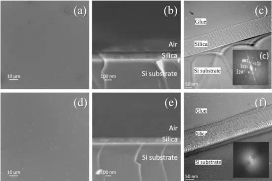
The FE-SEM top-view image of the sample S1.0-3M (Fig. 1a) shows fewer surface defects compared to the S1.5-1H surface (Fig. 1d). The mild temperature condition for the removal of the surfactant micelles and the shorter exposure time to ammonia resulted in less surface damage. The surface damage seen in Fig. 1d is not only due to the high calcination temperature but also to the excessive ammonia vapour treatment, which is known to rearrange the silica film surface. There- fore, dense micro-holes appeared on the surface. The size of these pin- holes is about 1–2 μm (Fig. 1a and 1d). The measured thickness values from the cross-sectional images are ~135–140 nm (Fig. 1b, S1.0–3 M) and ~135 nm (Fig. 1e, S1.5–1H).
Cross-sectional TEM micrographs were recorded from the silica layers on silicon substrate. Fig. 1c and 1f show the presence of well- ordered and reasonably ordered 3D periodic patterns of the meso- porous structure, respectively. The analysis of the FFT diffractograms obtained from the HRTEM images showed a distorted face centred cubic
Fig. 1. FE-SEM and HRTEM images of porous silica coatings on silicon, heat-treated at 120 ◦C (S1.0-3M, top row, a-b-c) and 480 ◦C (S1.5-1H, bottom row, d-e-f).
Top-view (a and d) and cross-sectional (b and e) SEM images, and cross-sectional HRTEM micrographs and their fast Fourier transform insets (c and f) representing the oriented mesoporous structure.
(fcc) pore structure with an Fm3m symmetry and a lattice constant of about 15.5 nm. Fan et al. reported earlier on fcc structure of mesoporous silica [39]. In the present study, the pore thickness is about 9.2 nm, and the pore wall thickness shows an average of 3 nm. The layer consists of domains showing various distortions of the fcc structure built up from pores that are slightly elongated parallel to the substrate. This elonga- tion modifies the ratio of 002 (planes parallel with the surface) and
− 220 lattice distances with respect to cubic structure and also, instead of 54.7◦we can measure larger and smaller angles between 002 and − 111 and between 002 and 111 reflections, respectively. In addition, unlike the perfect cubic structure, the 002 and − 220 reflections of the pore structure are not perpendicular to each other. A possible explanation for this angular distortion can be a shear effect due to pulling out the sub- strate from the sol during dip coating [40]. Another explanation for the deformation of both spherical pore shape and fcc structure can be given by the work of Lowe and Baker [41] that reported the collapse of the pore structure due to high-temperature treatment. One of the most important observation is the increase in pore sizes as a consequence of ammonia treatment. Pore sizes of silica coatings prepared without ammonia treatment are only in the range of 3–4 nm [4]. This can be attributed to the pseudomorphic transformation of mesoporous silica coatings, intensively studied by Grosso’s group [15].
The pseudomorphic transformation of the silica-micellar phase can be induced with alkaline treatment [18,42]. In our case, it was induced with aqueous ammonia vapours. The proposed mechanism relates to the dissolution and re-precipitation of the silica species [20] and the inter- action of silica aggregates and surfactant molecules induced by the base catalyst, such as NaOH or aqueous ammonia [43] taking place mainly in aqueous solutions. According to Grosso et al. [15], this transformation can also take place with freshly prepared micelle-containing silica coating samples, which are kept in aqueous ammonia vapour.
Comparing Fig. 1c to 1f, the calcination has an additional effect on the formation of the porous structure. Fig. 1f shows a double layer of the silica coating with a thickness ratio of about 1 to3 of the lower and upper layers. In the lower layer, in some areas, Moir´e–pattern appeared due to interference of overlapping domains with variously oriented ordered
pore structure. Such superimposed layers structure of mesoporous ma- terials are reported in the literature [44–47]. The HRTEM micrograph in Fig. 1f shows that the boundary between the two layers is irregular. The indexing of the FFT inset in Fig. 1f is the same as that of Fig. 1c, except that it shows arcs instead of point reflections. The arcs in the FFT inset indicate remarkable orientational undulation of the pore structure of the bilayer.
3.2. Spectroscopic ellipsometry studies
Ellipsometry measurement provided comparative information of coatings on transparent (polycarbonate, glass and quartz) as well as on non-transparent (silicon) substrates.
We applied different withdrawal speeds (1.0–4.5 cm⋅min−1) to pre- pare silica thin layers on four different substrates. All samples were treated in an ammonia atmosphere for 1 hour or 3 hours. The heat treatment of the samples was at 120 ◦C (M) and 480 ◦C (H). Table 1 includes the results from spectroscopic ellipsometry. The analysis of the fitted data showed that the two-layer optical model provided the best fitting results. The layer on the airside (upper layer =UL) had a lower porosity than the layer on the substrate side (lower layer =LL).
As can be seen in Table 1, the layer thickness correlates with the deposition rate and the curing temperature. The higher the deposition rate, the thicker the coating. The same applies to reduced thickness at a higher temperature. The optical stable coatings, P1.0–3M and G1.5–1H, consist of two layers.
The duration of the ammonia treatment and the temperature of the heat treatment influenced the porosity of the lower layer and the upper layer. We observed that the optimal ammonia treatment time was be- tween 1 hour and 3 hours. The light transmission of the samples decreased when we increased the exposure time of ammonia vapour.
The phenomenon can be analogous to pseudomorphic transformation observed for nanoparticles after a longer reaction time in an alkaline medium, which results in hollow sphere formation [12].
The mesoporous layer distribution on silicon showed a dependence on the applied curing temperature. If heat treatment was only 120 ◦C, Table 1
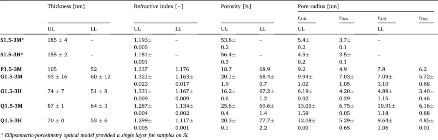
Layer thickness, refractive index, and porosity of the upper layer (UL) and the lower layer (LL). The samples were prepared on silicon (Si), polycarbonate (P), glass (G) and quartz (Q) substrates, treated in ammonia vapour (B) for 1 hour or 3 hours and measured by spectroscopic ellipsometry. The withdrawal speed was 1.0–4.5 cm⋅min−1 and the heat treatment was 120◦C (M) or 480 ◦C (H).
Samples Total thickness [nm] Thickness [nm] Refractive index [−] Porosity [%]
UL LL UL LL UL LL
S1.5-3M 180 180 ±2 1.2235±
0.0018 49.59 ±0.40
S1.5-3H 151 140 ±2 11 ±1 1.2131±
0.0033 1.1084±
0.0247 51.80 ±0.71 74.70 ±5.52
P1.0-3M 122 85 ±5 37 ±7 1.3448±
0.0066 1.1726±
0.0185 23.80 ±1.41 60.55 ±4.03
P1.5-3M 157 84 ±1 73 ±7 1.3277±
0.0043 1.1761±
0.0054 27.43 ±0.95 59.80 ±1.15
P2.0-3M 186 103 ±8 83 ±4 1.3109±
0.0127 1.2203±
0.0355 31.00 ±2.68 50.30 ±7.64
P3.0-3M 251 41 ±4 210 ±11 1.3016±
0.0203 1.2658±
0.0209 32.95 ±4.31 40.55 ±4.45
G1.5-3M 153 83 ±13 70 ±16 1.3139±
0.0075 1.1512±
0.018 30.36 ±1.58 65.23 ±3.91
G1.5-1H 112 58 ±2 54 ±4 1.2948±
0.0005 1.1195±
0.0067 34.40 ±0.14 72.25 ±1.48
G1.5-3H 122 77 ±4 45 ±5 1.3382±
0.0062 1.1330±
0.0064 25.20 ±1.30 69.23 ±1.41
G3.0-1H 167 79 ±3 88 ±4 1.2957±
0.0007 1.1091±
0.0046 34.2 ±0.14 74.55 ±1.06
G4.5-1H 221 91 ±2 130 ±1 1.2938±
0.0019 1.1067±
0.0022 34.6 ±0.42 75.05 ±0.49
Q1.5-3M 152 96 ±2 56 ±2 1.2962±
0.0049 1.1253±
0.0006 34.15 ±1.06 70.9 ±0.14
Q1.5-3H 127 76 ±3 51 ±4 1.3131±
0.0061 1.1018±
0.0026 30.55 ±1.34 76.20 ±0.56
there was no layer separation (S1.5–3M). This analysis was confirmed with the structure observed in the HRTEM image (Fig. 1c). The layer separation on silicon only occured at high temperature: it consisted of a thin lower-layer with 75% porosity and a thick upper-layer with 52%
porosity (S1.5–3H). Except for S1.5–3M samples, we observed the double-layer formation in all other samples, although the circumstances of preparation have influenced the layer specifications. The layers were distinguishable according to the double-layer fitting model.
Polycarbonate and glass substrates were coated at different with- drawal speeds. The increasing speed affected the porosity (Table 1). The porosity of the upper layer increased slightly (from 24% to 33%), and the porosity of the lower layer decreased significantly (from 60% to 40%).
In the case of samples on glass, the thickness of the upper layer and the lower layer was similar and seemed to be independent of the layer deposition rate. The average porosity of the bottom layer was 71% and 31% of the top layer (Table 1). The porosity ratio did not depend on the total thickness. Samples on glass had a lower refractive index than samples on polycarbonate. The two-layer formation was also observed for the samples on quartz.
Hereby, we summarise the spectroscopic ellipsometry results (Table 1). We observed that regardless of the deposition speed and the substrate, double-layer silica was formed. The layer at the substrate side (lower layer) had high porosity (41–76%). The porosity of the airside layer (upper layer) was significantly lower (24–52%).
3.3. Ellipsometric-porosimetry studies
Samples on silicon, polycarbonate, glass and quartz were also char- acterised with ellipsometric-porosimetry. The solvent vapour was introduced into the open pore system, and the absorption/desorption isotherms were recorded [48]. Toluene was used for the samples coated on Si substrates which had a high refractive index and thus pore filling caused a higher change in the effective refractive index of the porous layer leading to increased sensitivity. 2-propanol was used for the samples on the other substrates to prevent degradation. Due to the thin lower layer on Si (11±1 nm) obtained from spectroscopic ellipsometry, the Cauchy optical model offered no reliable results for the double-layer approach. Therefore, the double-layer ellipsometric-porosimetry fit dealt with the other three systems where the differences in thickness were significant. The presented results for Si samples in Table 2 were calculated with the single-layer approach, i.e. one layer with a refractive index dispersion described by a Cauchy formula.
Both refractive indices were calculated from the ellipsometry mea- surement. The refractive indices in Tables 1 and 2 differed only in the
second place of decimals. This difference can be attributed to the different fitting models. We calculated the refractive index in Table 1 with the EMA formula and in Table 2 with the Cauchy formula. The porosity of the samples in Tables 1 and 2 are not identical. The EMA model provided information about the entire pore system, and therefore the porosity values in Table 1 are higher. On the contrary, the Cauchy model calculated with open pores accessible to the adsorptive material (toluene and 2-propanol). Therefore, the porosity of the samples in Table 2 are smaller. During the characterisation process, we first measured all samples with ellipsometry, followed by outgassing at 140–150 ◦C and then measured them with ellipsometric-porosimetry.
This short and extra heating might affected the thickness and porosity of silica samples cured at 120 ◦C.
The pore sizes in Table 2 are in good agreement with the results of HRTEM investigations. The ammonia treatment resulted in a significant increase in pore sizes. As we mentioned in the previous section (Section 3.1), the pore sizes of silica coatings prepared without ammonia treat- ment were only in the range of 3–4 nm [4]. The layer separation as a consequence of ammonia treatment was also confirmed for PC, glass and quartz substrates (Table 2).
A catalysed transformation and rearrangement of the Si–O skeleton takes place when the samples are exposed to the ammonia atmosphere.
It was proposed that the increased number of deprotonated hydroxyl groups (R–O–) support the Ostwald ripening process, particularly on the micelle/silica interfaces [15]. This structural modification within the combination of surfactant-micelles and silicon-dioxide may produce layer separation analogous to the hollow sphere formation [12]. The rearrangement of the layer caused increased interior pore content on the side of the substrate. Regardless of the open porosity and the polar surface, the ammonia vapour treated samples have improved service life due to the increased number of siloxane (Si–O–Si) linkages compared to the non-treated samples [4]. Both layers have a mesoporous structure;
only the distribution of porosity is different. The porosity of the lower layer is always higher than the porosity of the upper layer. This unique arrangement is advantageous because the smaller mesoporosity [19].
We found that the interconnected pores after the pseudomorphic transformation are not only present in mesoporous silica particles [19, 20] but also in silica layers with mesopores.
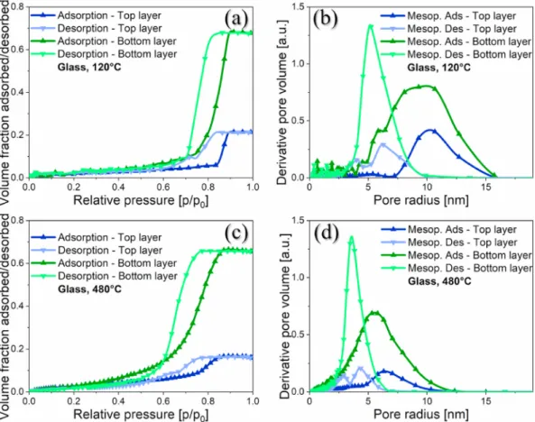
Fig. 2 shows the characteristic volume adsorption-desorption iso- therms, and the corresponding pore radius distribution curves calcu- lated from the modified Kelvin model for mesopores (focusing on samples on glass after consolidation at 120 ◦C - G1.5-3M and 480◦C - G1.5-3H). At first, the upper layer was blocked with capillary conden- sation and formed a triangular hysteresis loop of type H2 according to the IUPAC classification. This pore blocking or percolation effect has Table 2
Layer thickness, refractive index, porosity and pore radius (rads and rdes for adsorption and desorption measurements, respectively) of the upper layer (UL) and the lower layer (LL). The samples were prepared on silicon (S), polycarbonate (P), glass (G) and quartz (Q) substrates, treated in ammonia vapour for 3 hours (B) and measured by ellipsometric-porosimetry. The withdrawal speed was 1.5 cm ⋅ min−1 and the heat treatment was 120 ◦C or 480 ◦C.
Thickness [nm] Refractive index [− ] Porosity [%] Pore radius [nm]
rAds rDes rAds rDes
UL LL UL LL UL LL UL LL
S1.5-3M* 185 ±4 – 1.193±
0.005 – 53.8±
0.2 – 5.4±
0.2 3.7±
0.1 –
S1.5-3H* 155 ±2 – 1.181±
0.001 – 56.4±
0.3 – 4.5±
0.2 3.5±
0.1 –
P1.5-3M 105 52 1.337 1.176 18.7 68.9 9.2 4.9 7.8 6.2
G1.5-3M 93 ±16 60 ±12 1.321±
0.023 1.163±
0.017 20.1±
1.9 68.4±
0.7 9.94±
1.02 7.03±
1.05 7.09±
3.10 5.72±
0.68
G1.5-3H 74 ±7 51 ±8 1.331±
0.009 1.167±
0.009 16.2±
0.6 67.2±
1.2 6.19±
0.92 4.20±
0.29 4.89±
1.15 3.40±
0.46
Q1.5-3M 87 ±1 64 ±3 1.287±
0.004 1.134±
0.002 25.6±
0.4 69.6±
1.4 13.05±
1.59 6.75±
0.05 10.91±
1.18 6.16±
0.88
Q1.5-3H 70 ±0 53 ±6 1.299±
0.005 1.117±
0.001 20.3±
0.1 77.7±
2.2 12.08±
0.00 5.29±
0.65 9.64±
1.06 4.85±
0.01
* Ellipsometric-porosimetry optical model provided a single layer for samples on Si.
been studied intensively [49,50]. Pore radii reported in Table 2 are slightly larger in the upper layer, which should prevent pore-blocking during water vapour adsorption and delayed adsorption in the lower layer. We proposed a schematic illustration of the upper and lower layers with an interconnected pore system (Fig. 3). The bottom layer can be considered as an analogue of the body of the ink bottle, and it showed an adsorption isotherm type IV regardless of the curing temperature.
The main reason for the bilayer structure in this study is that
ammonia vapour concentration (2 M) was lower than in the study re- ported by Grosso et al. [15] (15 M) and, thus the pseudomorphic transformation was not complete. The pseudomorphic transformation utilized the higher solubility of silica at elevated pH and temperature to rearrange the silica/block co-polymer structure (i.e. minimize the overall energy).
3.4. Optical stability of silica coatings
We prepared silica sol-gel coatings on PC and glass substrates with pore-forming surfactants and dip-coating technique to improve the light transmission [4,5]. We found that the ammonia treatment of the freshly deposited layers ensured long term stability of optical properties on PC and glass substrates. The maximum transmission of the samples remained unchanged after 12 months of storage (>98% and >99%, respectively).
We stored these samples in a dust-free place under ambient condi- tions and measured them again after 4 years.
The transmission of mesoporous silica films can be influenced by the humidity since water easily condenses in the pores, which changes the refractive index. The relative humidity during the storage and the measurements was between 30% and 40%.
The results of the UV–Vis measurement can be seen in Fig. 4a (G1.5- 1H) and Fig. 4b (P1.0-3M). The spectra from the aged samples were compared to the freshly prepared samples. As can be seen, the light transmission curves showed only minor changes over time. The maximum light transmission on glass showed a decrease of 1.51% (from 99.79% to 98.28% at 536 nm), while these changes on polycarbonate were below 0.40%. A slight increment was present at lower wavelengths (from 97.40% to 97.61% at 513 nm).
According to the optical analysis from UV–Vis measurements, the Fig. 2. Volume adsorption-desorption isotherm and pore radius distribution of samples G1.5-3M (a, b) and G1.5-3H (c, d) on glass (G) substrate, measured with ellipsometric-porosimetry.
Fig. 3.The schematic illustration of the two layers with interconnected pore system.
porosity of silica coatings on polycarbonate remained unchanged (27%) after 4 years, but there was a slight deterioration of the layer thickness from 112 nm to 102 nm. It explains the slight transmission increment at lower wavelengths. On contrary, the porosity and layer thickness of the samples on glass decreased by 15% and 20 nm (from 37% to 22% and from 112 nm to 92 nm). These samples are less stable due to the Na+and Ca2+ion migration from the (soda-lime) glass into the silica matrix [51].
Ion diffusion from glass to coating is a slow process and occurs at room temperature (20–25 ◦C).
We prepared reference samples on glass and PC under the same conditions as G1.5-1H and P1.0-3M, but without ammonia treatment.
The samples on glass were monolayers with a thickness of 85 ±2 nm, a refractive index of 1.300 ± 0.004, and a porosity of 28% [4]. The samples on PC were also monolayers with a thickness of 101 ±1 nm, a refractive index of 1.368 ± 0.002, and a porosity of 18% [4]. We concluded that the porosity of the samples without ammonia treatment was lower than those of ammonia-treated samples. The maximum light transmission of the samples on glass without ammonia treatment was 99.59% at 459 nm after one day (G1.5-0H, Fig. 4c). It decreased to 96.37% at 544 nm after 4 years, which is a 3.22% transmission loss. The maximum light transmission of the untreated samples on polycarbonate was 97.02% at 478 nm after one day (P1.0-0M, Fig. 4d). It decreased to 93.33% at 463 nm after 4 years, which is a 3.69% transmission loss. We observed the partial collapse of the mesostructured monolayer anti-reflective coatings on glass (G1.5-0H). On the other hand, we observed the total collapse of the untreated mesostructured samples on polycarbonate within 90 days (P1.0-0M) [4]. Based on our measure- ments with UV-VIS spectroscopy, spectroscopic ellipsometry, and ellipsometric-porosimetry, the untreated silica film had no underlayer, it consisted of a single layer.
Regarding the surface properties of the substrates, the wettability of the polycarbonate is low, the advancing contact angle for distilled water is 80–82◦. In contrast, the surface of the glass substrate is hydrophilic,
the distilled water spread over the surface, and the advancing contact angle (CAA) is 2–10◦. It is known that the pure silicon surface is covered by a thin layer of native SiO2. The wetting properties of the silicon (CAA
=86–88◦) is similar to the polycarbonate, as well as the quartz (CAA = 32–34◦) to the glass. Therefore, we can exclude the substrate effect, since the pseudomorphic transformation mechanism was detected regardless of the type of the substrate.
The silica layer is partially soluble in water and an excess of water washing potentially could make the upper layer thinner and cause rearrangement of the structure.
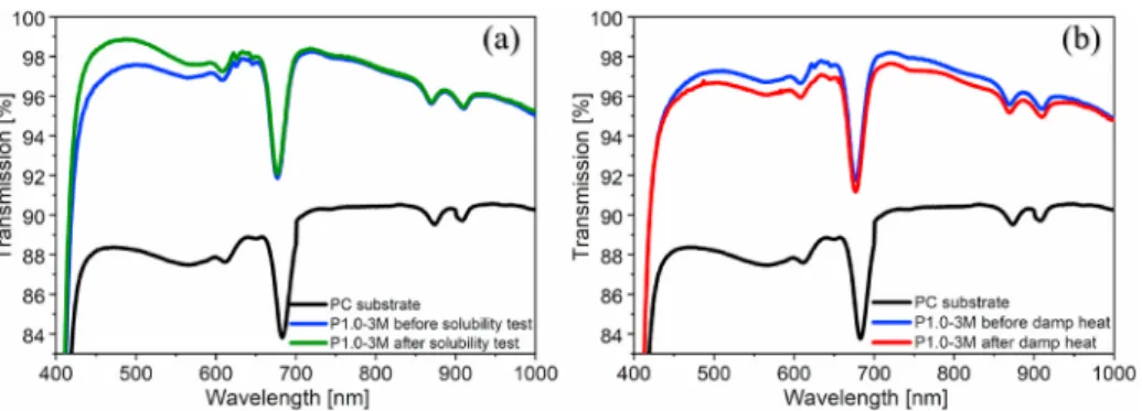
We measured the light transmission of the samples on PC before and after the specific tests (Fig. 5). After the solubility test, the maximum light transmission of the P1.0-3M samples increased by 1.44% (from 97.53% to 98.97% at 488 nm). The reason for increased light trans- mission is twofold. The six-hour soaking of the layers dissolved not only the residual surfactant from the pores, but also partially dissolved the silica matrix. After the damp heat test, the maximum light transmission of the samples P1.0-3M decreased by 0.64% (from 97.28% to 96.64% at 511 nm). The transmission loss after an accelerated environmental test is acceptable because the transmission loss of this type of ammonia-treated system on polycarbonate stored at room temperature is less than 0.40%
after 4 years. None of the samples after the ISO test received further treatment.
4. Conclusions
Mesoporous silica layers were prepared by sol-gel dip-coating tech- nique on silicon, polycarbonate, microscope glass slides and quartz substrate. Mesopores were formed by the soft templating method using Pluronic PE10500 triblock copolymer. The applied one-pot synthesis and circumstances promoted the formation of a double-layer structure.
Both layers had different porosity and pore size distributions. This unique structural change was due to the ammonia vapour treatment of Fig. 4.Transmission spectra of ammonia-treated samples on (a) glass - G1.5-1H and (b) polycarbonate - P1.0-3M and the same system without ammonia treatment on (c) glass - G1.5-0H and (d) polycarbonate -P1.0-0M, after one day and after 4 years of storage, measured with UV–Vis spectroscopy.
the as-deposited, template-containing samples. Ammonia treatment was not only responsible for the significant increase in pore sizes, but also the considerable difference in the porosity of the outer and the inner parts of the layer. Otherwise, the untreated samples were monolayers. This phenomenon can be analogous to pseudomorphic transformation observed for silica nanoparticles after a longer reaction time in an alkaline medium, resulting in hollow spheres. The experimental results showed that the special structural rearrangement did not depend on the substrate types and the different circumstances of the preparation. It had only influenced the relative thickness of the upper (outer) and the lower (inner) layer of the investigated samples. The denser outer layer pro- tected the coatings from environmental contamination and ensured a long-lasting optical stability. This structure arrangement was in accor- dance with the optical stability experiments. The presented silica bi- layers can provide a novel concept in terms of reduced reflectivity and extended life of porous materials.
Declaration of competing interest
The authors declare that they have no known competing financial interests or personal relationships that could have appeared to influence the work reported in this paper.
Acknowledgement
The authors are grateful for Attila Abrah´ ´am (Budapest University of Technology and Economics, Centre for Colloid Chemistry) for the preparation of the samples on quartz, Dr. D´aniel Z´amb´o for the FE-SEM investigations (Hungarian Academy of Sciences - Centre for Energy Research - Institute of Technical Physics and Materials Science - Chemical Nanostructures Laboratory) and Dr. Ildik´o Cora for discussions on the evaluation of TEM results (Centre for Energy Research, Institute of Technical Physics and Materials Science, Institute of Technical Physics and Materials Science). Gusztav Hantos (Department of Electron ´ Devices (EET), Budapest University of Technology and Economics) is acknowledged for carrying out the environmental tests of Damp heat test according to the ISO 9022–2:2015 standard.
This work was supported by the European Union’s Horizon 2020 research and innovation program (Grant agreement No 683541), and by the grant of National Research Development and Innovation Office (NKFIH), Hungary, grant number BME-IE-NAT TKP2020 and K-128266.
The presented invention is protected by a European patent (EP3472248). It is also granted in the United States of America (US2019177553), and Canada (CA3028375) with the title of “Antire- flection film and its use on a substrate”, which claims the beneficial arrangement of the two layers. The applicant is Hungaro Lux Light Kft.
(Andr´as Szalai, co-founder and owner), and the inventors are Zolt´an Horv´ ¨olgyi, J´anosn´e Kabai (deceased), Emoke Albert, Lenke K˝ ocs and ´ Csaba Ferenc Major.
Appendix A. Supplementary data
Supplementary data to this article can be found online at https://doi.
org/10.1016/j.vacuum.2021.110415.
References
[1] Q. Yang, X. Lin, B. Su, Molecular filtration by ultrathin and highly porous silica nanochannel membranes: permeability and selectivity, Anal. Chem. 88 (2016) 10252–10258, https://doi.org/10.1021/acs.analchem.6b02968.
[2] Q.-Q. Meng, X. Zhao, C.-Y. Lin, S.-J. Chen, Y.-C. Ding, Z.-Y. Chen, Figure of merit enhancement of a surface plasmon resonance sensor using a low-refractive-index porous silica film, Sensors 17 (2017) 1846, https://doi.org/10.3390/s17081846.
[3] R.K. Singh, K.D. Patel, K.W. Leong, H.W. Kim, Progress in nanotheranostics based on mesoporous silica nanomaterial platforms, ACS Appl. Mater. Interfaces 9 (2017) 10309–10337, https://doi.org/10.1021/acsami.6b16505.
[4] L. Kocs, E. Albert, B. Tegze, M. Kabai-Faix, C. Major, A. Szalai, P. Basa, ´ Z. H´orv¨olgyi, Silica sol-gel coatings with improved light transmittance and stability, Period. Polytech. - Chem. Eng. 62 (2018) 21–31, https://doi.org/
10.3311/PPch.10550.
[5] Z. H´orv¨olgyi, J. Kabai, E. Albert, L. K´ocs, C.F. Major, Antireflection Film and its Use on a Substrate, EP3472248, 2021.
[6] N. Kim, Recent progress of functional coating materials and technologies for polycarbonate, J. Coating Technol. Res. 14 (2017) 21–34, https://doi.org/
10.1007/s11998-016-9837-x.
[7] M. Faustini, L. Nicole, C. Boissi`ere, P. Innocenzi, C. Sanchez, D. Grosso, Hydrophobic, antireflective, self-cleaning, and antifogging sol-gel coatings: an example of multifunctional nanostructured materials for photovoltaic cells, Chem.
Mater. 22 (2010) 4406–4413, https://doi.org/10.1021/cm100937e.
[8] B. Tegze, E. Albert, B. Fodor, G. S´afr´an, Z. H´orv¨olgyi, Photoinduced processes of adsorbed and associated dye molecules in mesoporous titania coatings, Dyes Pigments 167 (2019) 109–119, https://doi.org/10.1016/j.dyepig.2019.04.017.
[9] R. Pareek, M.N. Kumbhare, C. Mukherjee, A.S. Joshi, P.D. Gupta, Effect of oil vapor contamination on the performance of porous silica sol-gel antireflection-coated optics in vacuum spatial filters of high-power neodymium glass laser, Opt. Eng. 47 (2008) 1–5, https://doi.org/10.1117/1.2844551.
[10] A. Abrah´ ´am, L. K´ocs, E. Albert, B. Tegze, B. Szolnoki, N. Nagy, G. S´afr´an, P. Basa, Z. H´orv¨olgyi, Durability of microporous hybrid silica coatings: optical and wetting properties, Thin Solid Films 699 (2020) 137914, https://doi.org/10.1016/j.
tsf.2020.137914.
[11] M. Laird, C. Carcel, E. Oliviero, G. Toquer, P. Trens, J.R. Bartlett, M. Wong Chi Man, Single-template periodic mesoporous organosilica with organized bimodal mesoporosity, Microporous Mesoporous Mater. 297 (2020) 110042, https://doi.
org/10.1016/j.micromeso.2020.110042.
[12] A. Galarneau, J. Iapichella, K. Bonhomme, F. De Renzo, P. Kooyman, O. Terasaki, F. Fajula, Controlling the morphology of mesostructured silicas by pseudomorphic transformation: a route towards applications, Adv. Funct. Mater. 16 (2006) 1657–1667, https://doi.org/10.1002/adfm.200500825.
[13] F. Fajula, Engineering of mesostructured silicas by pseudomorphism, J. Chem. Soc., Dalton Trans. (2006) 291–294, https://doi.org/10.1039/b615187f.
[14] François Fajula, Anne Galarneau, Combining phase separation with pseudomorphic transformation for the control of the pore architecture of functional materials: a review, Petrol. Chem. 59 (2019) 761–769, https://doi.org/
10.1134/S0965544119080061.
[15] M. Boudot, V. Gaud, M. Louarn, M. Selmane, D. Grosso, Sol–gel based hydrophobic antireflective coatings on organic substrates: a detailed investigation of ammonia vapor treatment (avt), Chem. Mater. 26 (2014) 1822–1833, https://doi.org/
10.1021/cm403787v.
[16] R. Xing, S.E. Rankin, Reactive pore expansion during ammonia vapor post- treatment of ordered mesoporous silica prepared with mixed glucopyranoside and cationic surfactants, Microporous Mesoporous Mater. 108 (2008) 65–76, https://
doi.org/10.1016/j.micromeso.2007.03.028.
Fig. 5.Transmission spectra of ammonia-treated P1.0-3M samples on polycarbonate before and after the (a) solubility test (distilled water, 6 h, 25 ◦C) and (b) damp heat test (RH >90%, 16 h, 55 ◦C), measured with UV–Vis spectroscopy.
[17] N. Pal, J.H. Lee, E.B. Cho, Recent trends in morphology-controlled synthesis and application of mesoporous silica nanoparticles, Nanomaterials 10 (2020) 1–38, https://doi.org/10.3390/nano10112122.
[18] T. Martin, A. Galarneau, F. Di Renzo, F. Fajula, D. Plee, Morphological control of mcm-41 by pseudomorphic synthesis, Angew. Chem. Int. Ed. 41 (2002) 2590–2592, https://doi.org/10.1002/1521-3773(20020715)41:14<2590::AID- ANIE2590>3.0.CO, 2-3.
[19] M.J. Reber, D. Brühwiler, Bimodal mesoporous silica with bottleneck pores, Dalton Trans. 44 (2015) 17960–17967, https://doi.org/10.1039/c5dt03082j.
[20] N. Zucchetto, M.J. Reber, L. Pestalozzi, R. Schmid, A. Neels, D. Brühwiler, The structure of mesoporous silica obtained by pseudomorphic transformation of SBA- 15 and SBA-16, Microporous Mesoporous Mater. 257 (2018) 232–240, https://doi.
org/10.1016/j.micromeso.2017.08.046.
[21] J. Nestor, A. Vílchez, C. Solans, J. Esquena, Facile synthesis of meso/macroporous dual materials with ordered mesopores using highly concentrated emulsions based on a cubic liquid crystal, Langmuir 29 (2013) 432–440, https://doi.org/10.1021/
la303801b.
[22] R. Ryoo, C.H. Ko, M. Kruk, V. Antochshuk, M. Jaroniec, Block-copolymer- templated ordered mesoporous silica: array of uniform mesopores or Mesopore− Micropore network? J. Phys. Chem. B 104 (2000) 11465–11471, https://doi.org/10.1021/jp002597a.
[23] L. Yang, H. Wu, J. Jia, B. Ma, J. Li, Synthesis of bimodal mesoporous silica with coexisting phases by co-hydrothermal aging route with P123 containing gel and F127 containing gel, Microporous Mesoporous Mater. 253 (2017) 151–159, https://doi.org/10.1016/j.micromeso.2017.06.037.
[24] K. Nakanishi, Y. Kobayashi, T. Amatani, K. Hirao, T. Kodaira, Spontaneous formation of hierarchical macro-mesoporous ethane-silica monolith, Chem. Mater.
16 (2004) 3652–3658, https://doi.org/10.1021/cm049320y.
[25] Y.J. Guo, X.T. Zu, X.D. Jiang, X.D. Yuan, S.Z. Xu, H.B. Lv, B.Y. Wang, Effect of ammonia treatment on laser-induced damage of nano-porous silica film, Optik 120 (2009) 437–441, https://doi.org/10.1016/j.ijleo.2007.11.001.
[26] P.F. Belleville, H.G. Floch, Ammonia-hardening of porous silica antireflective coatings, Sol-Gel Opt. III. 2288 (1994) 25–32, https://doi.org/10.1117/
12.188957.
[27] I.M. Thomas, A.K. Burnham, J.R. Ertel, S.C. Frieders, Method for reducing the effect of environmental contamination of sol-gel optical coatings, Proc. SPIE 3492 (1999) 220–229, https://doi.org/10.1117/12.354236.
[28] D. Grosso, How to exploit the full potential of the dip-coating process to better control film formation, J. Mater. Chem. 21 (2011) 17033–17038, https://doi.org/
10.1039/c1jm12837j.
[29] M. Faustini, B. Louis, P.A. Albouy, M. Kuemmel, D. Grosso, Preparation of sol-gel films by dip-coating in extreme conditions, J. Phys. Chem. C 114 (2010) 7637–7645, https://doi.org/10.1021/jp9114755.
[30] E. Hild, A. De´ak, L. Nasz´alyi, O. Sepsi, N. ¨ Abrah´ ´am, Z. H´orv¨olgyi, Use of the optical admittance function and its WKB approximation to simulate and evaluate transmittance spectra of graded-index colloidal films, J. Opt. Pure Appl. Opt. 9 (2007) 920–930, https://doi.org/10.1088/1464-4258/9/10/023.
[31] H.P. William, A.T. Saul, T.V. William, P. Flaneery Brian, Numerical Recipes in C - the Art of Scientific Computing, 1992.
[32] H.A. Lorentz, Leipzig, B.G. Teubner, in: The Theory of Electrons and its Applications to the Phenomena of Light and Radiant Heat, G.E. Stechert, New York, 1916.
[33] D. Grigoriev, D. Gorin, G.B. Sukhorukov, A. Yashchenok, E. Maltseva, H. M¨ohwald, Polyelectrolyte/magnetite nanoparticle multilayers: preparation and structure characterization, Langmuir 23 (2007) 12388–12396, https://doi.org/10.1021/
la700963h.
[34] K.P. Mogilnikov, M.R. Baklanov, Determination of young’s modulus of porous low- k films by ellipsometric porosimetry, Electrochem. Solid State Lett. 5 (2002) F29–F31, https://doi.org/10.1149/1.1517771.
[35] X. Zhang, J. Qiu, X. Li, J. Zhao, L. Liu, Complex refractive indices measurements of polymers in visible and near-infrared bands, Appl. Opt. 59 (2020) 2337, https://
doi.org/10.1364/ao.383831.
[36] G. S´afr´an, N. Sz´asz, E. S´afr´an, Two-in-One sample preparation for plan-view TEM, Microsc. Res. Tech. 78 (2015) 599–602, https://doi.org/10.1002/jemt.22513.
[37] International Organization for Standardization, Optics and Photonics — Environmental Test Methods — Part 2: Cold, Heat and Humidity, 2015. ISO 9022- [38] 2. International Organization for Standardization, Optics and Photonics — Optical
Coatings — Part 4: Specific Test Methods, 2012. ISO 9211-4.
[39] J. Fan, C. Yu, F. Gao, J. Lei, B. Tian, L. Wang, Q. Luo, B. Tu, W. Zhou, D. Zhao, Cubic mesoporous silica with large controllable entrance sizes and advanced adsorption properties, Angew. Chem. Int. Ed. 42 (2003) 3146–3150, https://doi.
org/10.1002/anie.200351027.
[40] M. Klotz, P.A. Albouy, A. Ayral, C. M´enager, D. Grosso, A. Van Der Lee, V. Cabuil, F. Babonneau, C. Guizard, The true structure of hexagonal mesophase-templated silica films as revealed by X-ray scattering: effects of thermal treatments and of nanoparticle seeding, Chem. Mater. 12 (2000) 1721–1728, https://doi.org/
10.1021/cm991198t.
[41] J.B. Lowe, R.T. Baker, Deformation of ordered mesoporous silica structures on exposure to high temperatures, J. Nanomater. 2014 (2014), https://doi.org/
10.1155/2014/754076.
[42] H. Zhou, J. Sun, B. Ren, F. Wang, X. Wu, S. Bai, Effects of alkaline media on the controlled large mesopore size distribution of bimodal porous silicas via sol-gel methods, Powder Technol. 259 (2014) 46–51, https://doi.org/10.1016/j.
powtec.2014.03.060.
[43] Q. Cai, Z.S. Luo, W.Q. Pang, Y.W. Fan, X.H. Chen, F.Z. Cui, Dilute solution routes to various controllable morphologies of MCM-41 silica with a basic medium, Chem.
Mater. 13 (2001) 258–263, https://doi.org/10.1021/cm990661z.
[44] Y.Q. Yeh, C.Y. Tang, C.Y. Mou, Two-dimensional crystals of mesoporous silica SBA- 15 nanosheets with perpendicular and open channels, Apl. Mater. 2 (2014) 113303, https://doi.org/10.1063/1.4897203.
[45] R. Wang, Q. Chen, F.R. Chen, J.J. Kai, L.M. Peng, Defects and domain structures in SBA-16 mesoporous films with 3D cubic structure, Chem. Phys. Lett. 411 (2005) 463–467, https://doi.org/10.1016/j.cplett.2005.06.079.
[46] B.G. Trewyn, C.M. Whitman, V.S.Y. Lin, Morphological control of room- temperature ionic liquid templated mesoporous silica nanoparticles for controlled release of antibacterial agents, Nano Lett. 4 (2004) 2139–2143, https://doi.org/
10.1021/nl048774r.
[47] F.-F. Xu, F.-M. Cui, M.-L. Ruan, L.-L. Zhang, J.-L. Shi, Structural characteristics of oriented mesostructured silica thin films, Langmuir 26 (2010) 7535–7539, https://
doi.org/10.1021/la904340m.
[48] C. Robertson, A.W. Lodge, P. Basa, M. Carravetta, A.L. Hector, R.J. Kashtiban, J. Sloan, D.C. Smith, J. Spencer, A. Walcarius, Surface modification and porosimetry of vertically aligned hexagonal mesoporous silica films, RSC Adv. 6 (2016) 113432–113441, https://doi.org/10.1039/c6ra23059h.
[49] M. Thommes, B. Smarsly, M. Groenewolt, P.I. Ravikovitch, A.V. Neimark, Adsorption hysteresis of nitrogen and argon in pore networks and characterization of novel micro- and mesoporous silicas, Langmuir 22 (2006) 756–764, https://doi.
org/10.1021/la051686h.
[50] J. Loizillon, B. Baumgartner, C. Sinturel, M. Abbarchi, B. Lendl, D. Grosso, In-depth study of coating multimodal porosity using ellipsometry porosimetry in desorption scanning mode, J. Phys. Chem. C 123 (2019) 23464–23479, https://doi.org/
10.1021/acs.jpcc.9b05099.
[51] G. Heisch, E. R¨adlein, G.H. Frischat, On the origin of the aging process of porous SiO2 antireflection coatings, J. Non-Cryst. Solids 265 (2000) 193–197, https://doi.
org/10.1016/S0022-3093(99)00880-7.