DOKTORI (PhD) ÉRTEKEZÉS
VÖRÖSHÁZI ZSOLT
Veszprém
2009
University of Pannonia
Information Science and Technology Doctoral School
Investigation of Emulated-Digital
CNN-UM architectures: Retina model and Cellular Wave Computing architecture
implementation on FPGA
Ph.D. Thesis
Zsolt Vörösházi
Supervisor: Péter Szolgay (DSc)
Veszprém
2009
I dedicate this thesis work to the fadeless memory of my parents.
Investigation of Emulated-Digital CNN-UM architectures:
Retina model and Cellular Wave Computing architecture implementation on FPGA
Értekezés doktori (PhD.) fokozat megszerzése érdekében.
Írta: Vörösházi Zsolt
Készült a Pannon Egyetem, Informatikai Tudományok Doktori Iskolája (ITDI) keretében Témavezető: Dr. Szolgay Péter
...
Elfogadásra javaslom: (igen / nem) (aláírás)
A jelölt a doktori szigorlaton ... % -ot ért el, Az értekezést bírálóként elfogadásra javaslom:
Bíráló neve: ... igen /nem
...
(aláírás) Bíráló neve: ... igen /nem
...
(aláírás) A jelölt az értekezés nyilvános vitáján ...% - ot ért el.
Veszprém, ...
a Bíráló Bizottság elnöke
A doktori (PhD.) oklevél minősítése ...
...
az EDT elnöke
Acknowledgement
First of all, I would like to thank the invaluable help of my supervisor Prof. Péter Szolgay who supported my studies and research work both technically and financially throughout my PhD years. Under his constant and careful guidance I reckon him as my
‘second father’.
The valuable comments and many helps of Dr. Zoltán Nagy are gratefully acknowledged. He is the person, who enthusiastically introduced me into the mystery techniques of the rapid prototyping development on FPGAs. He always helped me with good ideas and taught me for analytical thinking.
Also grateful thanks to my dear friends and former colleagues at the CNN Applications Laboratory and other laboratories of the Image Processing and Neurocomputing Department, University of Pannonia (Zoltán Kincses, Sándor Kocsárdi, Péter Kozma, Péter Sonkoly, András Kiss, Mária Csiba-Bokrossy, and Dr. László Czúni), hence I got many helps both technically and personally.
Moreover, grateful thanks to my former colleagues and friends at the Analogic and Neural Computing Laboratory, MTA SZTAKI (Prof. Tamás Roska, Dr. Péter Keresztes, Péter Jónás, Dr. Timót Hidvégi, and Péter Tóth).
Last, but not least, I would like to thank the long patience and constant support of my family, my unforgotten parents and my ‘darling’, Judit.
Abstract
Investigation of Emulated-Digital CNN-UM architectures:
Retina model and Cellular Wave-Computing architecture implementation on FPGA
Recently, the parallel array processing has become the focus point of the state-of-the-art analog circuit technology and its digital counterpart. Cellular Neural / Nonlinear Networks (CNN) are defined as analog, non-linear, parallel computing structure of array including a lot of elementary processor units (e.g. nucleus) arranged in a two-dimensional regular grid.
The program of the CNN network (called ‘template’) can be defined by the strength of the local interconnections between the elementary cells. CNN is proved to be very efficient in several real time image-, and signal-processing tasks, especially where the complex spatio- temporal dynamics must be computed. If each elementary CNN cell is extended with a local analog and logical memory unit, a local controlling unit, and an optical sensor input, moreover, adding a Global Analogic Programming Unit (GAPU) to this integrated cell array a CNN Universal Machine (CNN-UM) architecture can be constructed.
Today’s modern FPGAs provide good alternative to perform complex spatio-temporal, multi-layer CNN dynamical computations at high precision owing to their advantageous features, such as high flexibility and computing performance, rapid prototyping development, and low cost in low volume.
This dissertation demonstrates how to implement the neuromorphic CNN-based mammalian retina model and the CNN-UM Global Analogic Programming Unit by using FPGA-based reconfigurable computing devices. For these specific tasks, based on the previously elaborated Falcon emulate-digital CNN architecture, new configurable computing architectures are elaborated on FPGA. The computing precision of the presented architectures can be configured which makes it possible to occupy only the required amount of resources during the computations of the CNN dynamics. The proposed emulated-digital implementation of the multi-channel retina model and the CNN-UM GAPU extension is compared with concurrent CNN-based solutions from three key aspects, which are: processing speed, number of physical cells, and accuracy.
Kivonat
Emulált-digitális CNN-UM architektúrák vizsgálata:
Retina modell és Celluláris Hullámszámítógép implementációja FPGA-n
Az utóbbi években mind az analóg, mind pedig a digitális áramköri technológia területén a párhuzamos tömbprocesszálás megvalósítása került előtérbe. A Celluláris Neurális /Nemlineáris Hálózatok (CNN) egy lokálisan összekötött, 2D-s síkon elhelyezkedő, analóg működésű nemlineáris számítási egységeket (elemi cellákat) tartalmazó, párhuzamos processzáló tömbként definiálható. A hálózat programját, a számítási egységek közötti összeköttetéseket meghatározó lokális interakciós erősségek, ún. „template-k” beállítása jelenti. A CNN hálózatok bizonyítottan igen hatékonyak a valós idejű kép és jelfeldolgozási feladatokban, ahol sok esetben valamilyen komplex tér-időbeli dinamikai számításokat kell elvégezni. Ha a CNN-hálózat mindenegyes elemi celláját lokális analóg/ logikai memória elemmel, lokális vezérlő egységgel és optikai érzékelő bemenettel egészítjük ki, valamint az így kibővített processzáló hálózathoz egy globális vezérlő egységet illesztünk, kapjuk meg a CNN Univerzális Gép (CNN-UM) architektúrát.
A mai modern FPGA-s rendszerek a nagyfokú flexibilitásukkal, nagy számítási teljesítményükkel, és gyors prototípusfejlesztési – ezáltal olcsó kihozatali költségükkel – igen jó alternatívát teremtenek a komplex tér-időbeli, többrétegű CNN dinamikai számítások nagy pontosságú végrehajtásához.
A disszertáció bemutatja, hogyan lehet a neuromorf felépítésű CNN-alapú emlős retina modellt, illetve egy önálló működést biztosító CNN-UM Globális Analogikai Vezérlő egységet megvalósítani az FPGA alapú újrakonfigurálható számítási eszközök alkalmazásával. A szerző a feladatokhoz a korábban kidolgozott Falcon emulált-digitális CNN architektúrát felhasználva egy új számítási architektúrákat dolgozott ki. Mindkét bemutatott architektúra számítási pontossága konfigurálható, amely lehetővé teszi, hogy csak a szükséges erőforrásokat foglaljuk le a CNN dinamika számítása során. A javasolt emulált-digitális implementáció, mind a többcsatornás retina modell, mind pedig CNN-UM GAPU esetében más konkurens CNN-alapú megvalósításokkal is össze lett hasonlítva a legfontosabb szempontokat figyelembe véve, amelyek a következők: feldolgozási sebesség, fizikai cellák száma, és pontosság.
Auszug
Untersuchung der Emulierten-Digitalen CNN-UM Architekturen:
Implementation des Retina-Modells und des Zellularen Wellenrechners in FPGA
In den letzten Jahren ist die Verwirklichung der parallelen Blockverarbeitung sowohl auf dem Gebiet der analogen als auch auf dem der digitalen Stromkreistechnologie in den Vordergrund gerückt. Die Zellularen Neuralen/Nicht-Linearen Netze (CNN) können als ein lokal verbundener, zweidimensionaler, analog funktionierende nichtlineare Rechnungseinheiten (Elementarzellen) enthaltender paralleler Verarbeitungsblock definiert werden. Unter dem Programm des Netzes versteht man die Einstellung der so genannten templates, d. h. der lokalen Interaktionsstärken, die die Verbindung zwischen den Rechnungseinheiten bestimmen. Die CNN-Netze sind – wie bewiesen – sehr effizient in den „real time“ Bild- und Zeichenverarbeitungsaufgaben, wo in vielen Fällen irgendwelche komplexe räumlich-zeitliche dynamische Rechnungen vorgenommen werden müssen.
Wenn jede einzelne Elementarzelle des CNN-Netzes durch lokale analoge/logische Speicherzelle, lokale Steuerungseinheit und optischen Sensoreingang ergänzt wird, sowie an das auf diese Weise erweiterte Verarbeitungsnetz eine globale Steuerungseinheit angeschlossen wird, bekommen wir die Architektur der CNN Universalmaschine (CNN- UM).
Die heutigen modernen FPGA-Systeme bieten durch ihre große Flexibilität, große Rechnungskapazität und ihre schnelle Prototypentwicklung – und dadurch billige Kosten – eine ziemlich gute Alternative zur präzisen Durchführung der komplexen zeitlich- räumlichen, mehrschichtigen CNN dynamischen Rechnungen.
Die Dissertation stellt vor, wie man das neuromorph aufgebaute Retina-Modell auf CNN-Basis, sowie die selbständiges Funktionieren sichernde CNN-UM globale analoge Steuerungseinheit mit Anwendung der wiederkonfigurierbaren Rechnungsmittel auf FPGA- Basis verwirklichen kann. Der Autor hat zu diesen Aufgaben neue Rechnungsarchitekturen ausgearbeitet, indem er die früher ausgearbeitete Falcon emulierten-digitalen CNN-UM Architektur angewendet hat. Die Rechnungspräzision beider vorgestellten Architekturen ist konfigurierbar, wodurch ermöglicht wird, dass lediglich die nötigen Ressourcen bei der Rechnung der CNN-Dynamik beansprucht werden. Die vorgeschlagene emulierten- digitalen Implementation wurde sowohl im Falle des mehrpoligen Retina-Modells als auch in dem von CNN-UM GAPU mit anderen Verwirklichungen auf CNN-Basis verglichen.
Dabei wurden die folgenden wichtigen Aspekte in Betracht gezogen:
Verarbeitungsgeschwindigkeit, Zahl der physikalischen Zellen und Präzision.
Contents
Acknowledgement... iii
Abstract...iv
Kivonat...v
Auszug...vi
Contents ... vii
Acronyms...x
Introduction...1
Chapter 1. Cellular Neural / Non-linear Networks and their hardware realizations ....4
1.1 Introduction to CNN ...4
1.1.1 CNN theorem: definitions...4
1.1.2 CNN’s dynamic and circuit model ...6
1.1.3 Cloning templates ...7
1.2 CNN Universal Machine as a Cellular Wave Computer ...8
1.2.1 Architecture of CNN-UM...9
1.2.2 The Global Analogic Programming Unit (GAPU) ...10
1.3 Simulation of the CNN dynamics...12
1.3.1 Software Simulation ...12
1.3.2 Analog/mixed-signal VLSI CNN implementations...13
1.4 The Emulated-Digital CNN-UM approaches ...13
1.4.1 CNN-HAC: a digital hardware accelerator board using DSP...13
1.4.2 CASTLE: a full-custom, emulated-digital VLSI CNN-UM processor array ...14
1.4.3 FALCON: a configurable CNN architecture on FPGA...19
1.5 Summary...23
Chapter 2. FPGA as Reconfigurable Computing Device...24
2.1 Introduction...24
2.2 FPGA overview ...24
2.2.1 Basic Structure...25
2.2.2 Granularity of structure...25
2.2.3 Routing interconnect...26
2.2.4 Configuration modes...27
2.3 Architecture of Xilinx FPGAs ...28
2.3.1 CLB...28
2.3.2 IOB...29
2.3.3 Dedicated resources ...29
2.3.4 Embedded processors ...29
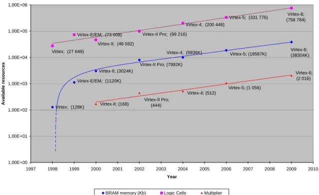
2.4 Moore’s law: trends in microprocessors and FPGA technology ...30
2.5 HW-SW co-design...32
2.6 EDA Tools for Reconfiguration ...33
2.6.1 Agility DK Design Suite...34
2.6.2 Handel-C language ...35
2.6.3 Xilinx development tools...36
2.7 Summary...37
Chapter 3. A Neuromorph retina model implementation on FPGA ...38
3.1 Introduction...38
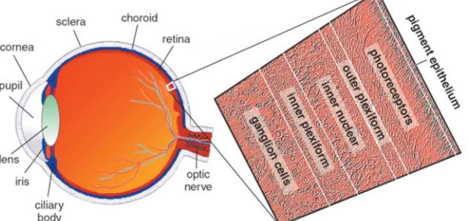
3.1.1 Physiology of the retina ...38
3.1.2 Parallel processing in the retina ...40
3.1.3 Evolution of the retina model studies ...41
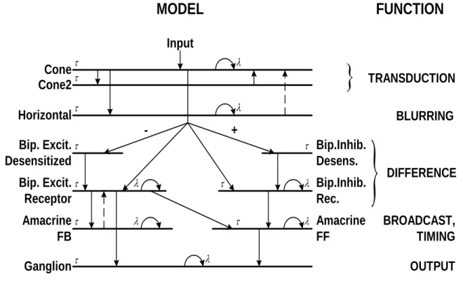
3.2 CNN-based mammalian retina model...42
3.2.1 Neuromorph model backgrounds...42
3.2.2 Types of Receptive Field (RF) organization...45
3.2.3 Retina Model Parameters...45
3.2.4 Different implementations of the CNN-based neuromorphic retina model ...48
3.3 Objective: Retina model implementation on FPGA ...50
3.3.1 Processing flow...50
3.3.2 Modified Falcon core for multi-layer retina processing ...51
3.3.3 Optimization of the arithmetic unit...52
3.3.4 Real-time test environments ...54
3.4 Device utilization...56
3.4.1 Number of implementable cores...58
3.5 Performance ...59
3.5.1 Software simulations...59
3.5.2 Computing performance and I/O memory bandwidth comparisons on different FPGAs...62
3.6 Accuracy of solution vs. computing precision...65
3.7 Example: emulating multi-channel retina model...68
3.8 Summary...69
Chapter 4. Cellular Wave Computing Architecture implementation on FPGA ...70
4.1 Introduction...70
4.2 Motivations to elaborate a Cellular Wave Computing Architecture on FPGA ...71
4.3 Requirements ...72
4.4 Falcon: architecture optimization ...74
4.5 Implementation of the Vector Processing Element ...76
4.6 Implementation of the GAPU ...77
4.6.1 Architecture of GAPU ...78
4.6.2 Operating steps ...79
4.6.3 The real image-processing system...80
4.7 Device Utilization ...81
4.8 Results and performance...83
4.8.1 Solving a complex example...83
4.8.2 Results...85
4.8.3 Performance comparisons...86
4.9 Summary...90
Conclusions...92
Theses...94
Thesis Group 1: Implementation of a CNN-based neuromorph mammalian retina model on FPGA architecture ...94
Thesis Group 2: Implementation of embedded CNN-UM Global Analogical Programming Unit as a Cellular Wave Computer on FPGA architecture...96
The Author’s Publications ...99
Journal Papers ...99
International Conference Papers...99
Tézisek (magyar nyelven)...101
1. Téziscsoport: Emlős retina modell implementációja FPGA architektúrán ...101
2. Téziscsoport: Beágyazott CNN-UM Globális Analogikai Vezérlő Egység, mint Celluláris Hullámszámítógép implementációja FPGA architektúrán...103
Bibliography ...106
Acronyms
ASIC – Application Specific Integrated Circuits BRAM – Block RAM
CLB – Configurable Logic Block
CNN – Cellular Neural / Nonlinear Networks CNN-UM – CNN Universal Machine
DSP – Digital Signal Processing EDA – Electronic Design Automation EDK – Embedded Development Kit FPE – Falcon Processor Element
FPGA – Field Programmable Gate Arrays GAPU – Global Analogic Programming Unit IOB – I/O Block
IPL – Inner Plexiform Layer MAC – Multiply-and-Accumulate ML – Multi Layer
MULT – Multiplier
OPL – Outer Plexiform Layer
PDE – Partial Differential/Difference Equation PLB – Processor Local Bus
PLD – Programmable Logic Device RC – Reconfigurable Computing
RISC – Reduced Instruction Set Computer SDK – Software Development Kit
SOC – System-On-a-Chip
VLSI – Very Large Scale Integration VPE – Vector Processing Element
Introduction
Nowadays, both the analog- and the digital circuit technology, and fabrication are continuously improving and supplementing each other. This improvement is well featured by the scaling-down (micro-minimalization) effect based on the Moore’s law [1], [2]. The choice between these two technologies in case of the high-performance, real-time, and near-sensor signal processing tasks is primarily determined by the method of the application. To support the decision critical and typical physical parameters are calculated, such as area (A), speed (S), dissipated power (P) of the complex large-scale integrated VLSI circuits.
Recently, the parallel array processing has become the focus point of the state-of-the-art analog circuit technology and its digital counterpart. However, following this type of design methodology an important problem was emerged: most of designers and researchers intended to construct a globally interconnected processor array structure, but its complexity grows exponentially according to the increasing number of processor elements in an array.
Cellular Neural / Nonlinear Networks (CNN) [3],[4] are defined as analog, non-linear, parallel computing structure of array including a lot of elementary processor units (e.g.
nucleus) arranged in a 2-dimensional regular grid. They can be implemented not only in a single-layer, but well formed in a multi-layer architecture, as well. The processor elements are locally connected (discrete) in space, but they operate continuously in time. The program of the CNN network (called ‘template’) can be defined by the strength of the local interconnections between the elementary cells, or in other words by setting the matrices of the weighting factors. The result of the computation is derived from both the spatio- temporal dynamic of the processing elements and the template operations (called analog transient) together.
If each elementary CNN cell is extended with a local analog and logical memory unit, a local controlling unit, and an optical sensor input, moreover adding a global programming unit to this integrated cell array a CNN Universal Machine (CNN-UM) architecture can be constructed [5]. This novel type of computing infrastructure is also referred to as “Cellular Wave Computing Architecture” [68]. The CNN-UM is universal both in terms of Turing Machine and it may work as a non-linear computing operator [6]. Each elementary instruction of the CNN-UM defines complex, spatio-temporal dynamic behavior. The architecture of CNN-UM is summarized in Chapter 1.
In the present era, this novel computing architecture based on the CNN paradigm has been implemented on several different platforms. First hardware prototypes of the CNN networks contained analog / mixed-signal VLSI chips [7-9]. The huge computing performance of these CNN chips (a few TeraOPS - 1012 operations/sec) far exceeds the performance of all the other digital processor implementations, and the power dissipation is very low. However, they have some disadvantages, which impede their wide spread usability in the industrial applications. They are suffered from noise-sensitivity, lack of flexibility, and – as the most important problem – the limited “analog” accuracy (about 7-8 bits in I/O) giving inaccurate solution in most of signal processing tasks.
The simplest, most accurate, and most flexible, but slowest CNN-UM implementation is the CNN software simulator running on a traditional computer [10], [11]. The software simulator is generally used to ease the template design and optimization process. Moreover, during the measurements some comparisons should be made between the speed-up of
different CNN-UM approaches and the computing performance of the CNN software simulator, which latter is considered as a unit. As an alternate way, CNN software simulation can be accelerated by many-core technologies using GPU-based (Graphics Processor Unit) implementations, such as the NVidia CUDA [12], or the IBM CELL architecture [13].
The “emulated-digital” CNN-UM solution means a good trade-off between the analog VLSI CNN-UM implementations and software simulators – regarding computing performance and accuracy. The emulated-digital solutions have many different physical forms, such as VLSI ASIC (Application Specific Integrated Circuit) like the CASTLE array processor [14-15], the DSP-based (Digital Signal Processor) CNN-HAC prototyping board [16], or they can be built up on an FPGA (Field Programmable Gate Array) e.g. the FALCON architecture [17]. In case of this emulated-digital approach the behavior of the analog CNN cell network can be approximated by discretized model in space and time, while the locally connected digital processor elements are arranged in an array.
Hence, the nature of CNN provides a flexible and effective computing structure for the complex spatio-temporal dynamical computations of various bio-inspired systems (such as a retina), moreover it makes possible to generate the activity patterns in video real-time, as well [17]. The “neuromorph” structure of the multi-layer CNN retina model is derived from both morphological and electro-physiological information measured by neurobiologist.
According to the latest results of neurobiological investigations a mammalian rabbit retina consists of about 10-12 different types of ganglion channels, but further channels might be explored due to improvements in the methodology and measurement techniques.
Each channel is made up from several (at least 10) diversely inter-connected stack of strata, on which large number of simple processor elements (neurons) are arranged on a two-dimensional structure. The difficulty lies in this evolvable computing problem, that we could handle large number of CNN layers with different physical-timing parameters, and various connectivity properties beyond the increased computation power requirements.
Universality of a CNN-UM network is based on the stored-programming principle, which task can be solved by integrating an embedded Global Analogic Programming Unit (GAPU) into the cell network [5]. This GAPU is responsible for controlling the sequential instructions of the complex, sophisticated analogical (analog-logical) CNN algorithms;
moreover, it can store the necessary values (input, state, bias) to perform the computations.
I have chosen the FPGA-based reconfigurable computing devices both for neuromorph structured mammalian retina model implementation [19] and for elaboration of Global Analogic Programming Unit [20]. The reason is that today’s modern FPGAs provide good alternative to perform complex spatio-temporal, multi-layer CNN dynamical computations at high precision owing to their advantageous features, such as high flexibility and computing performance, rapid prototyping development, and low cost (in low volume).
Therefore, it is worthwhile to review the different CNN-UM approaches – especially regarding the emulated-digital CNN-UM implementations. It is very interesting how its inherent computational potential can be exploited during the solution of various real-time processing tasks [21].
The first two chapters are brief introduction into the fundamentals of Cellular Neural/Nonlinear Networks and Xilinx FPGAs as Reconfigurable Computing (RC) devices are described. Several physical implementations and performance comparisons of the various emulated digital CNN-UM approaches are mentioned. In the second part an application of the emulated-digital CNN-UM architectures is introduced performing the
real-time computations of different mammalian retina channels, in Chapter 3. An FPGA- based fully-functional stand-alone CNN-UM system is described in the Chapter 4., which is capable of running sophisticated analogical CNN operations in real-time. In conclusion, in Chapter 5 the new scientific results are described and formed into two main thesis groups.
Chapter 1. Cellular Neural / Non-linear Networks and their hardware realizations
1.1 Introduction to CNN
Cellular Neural / Nonlinear Network (CNN) technology is both a revolutionary concept and an experimentally proven new computing paradigm [3-4]. On one hand, the analogic cellular computers based on CNNs are set to change the way analog array signals are processed and are paving the way to an entire new analog computing industry. On the other hand, progressions of digital technique make it possible to construct these CNN arrays not only in analogue, but on several different digital hardware realizations. Although its prime focus is on visual computing, the concepts and techniques described in this section can be utilized in other different areas of research, including modeling of complex biological, chemical, or physical processes, as well.
The CNN was invented first by Leon O. Chua and Lin Yang at the University of Berkeley in 1988 [3]. The analog dynamic processors or cells accepting and generating analog signals, while the time is continuous and the interaction values between the cells are also real values. However, the proper definition of the „cloning template”, meaning the representation of the local interconnection patterns, is most crucial. This allows not only modeling but also engineering of complex dynamical systems.
The CNN computing architecture is the CNN Universal Machine (CNN-UM) [5] or called as Cellular Wave Computing Architecture [68], which can be implemented in various physical forms, discussed also here. The CNN Universal Machine is universal not only in a Turing sense but also on analog array signals [6]. Owing to the principle of stored programmability (invented by John von Neumann) it is also open to human intelligence with a practically limitless capability within the universe of analog array signals, via analogic spatio-temporal algorithms and software. This new world opened by the analogic CNN computing paradigm is nowadays a reality. In addition to the huge image and video processing power of the CNN Universal Machines, its unique bio-inspired, natural architecture could be exploited to implement various information processing tasks. In modern image processing, PDE-based techniques are becoming the most challenging and important new directions.
1.1.1 CNN theorem: definitions
A standard CNN architecture consists of an M×N rectangular 2D-array of cells C(i, j) with Cartesian coordinates (i, j), where i = 1, 2, . . . , M, j = 1, 2, . . . , N , as shown in Figure 1.1). The sphere of influence, Sr(i, j), of the radius r of a given cell C(i, j) is defined to be the set of all the neighborhood cells satisfying the following property Eq(1.1):
{ }
1 ,
1
( , ) ( , ) | max , ,
r k M
l N
S i j C k l k i l j r r
≤ ≤≤ ≤
⎧ ⎫
⎪ ⎪
=⎨ − − ≤
⎪ ⎪
⎩ ⎭
∈`
⎬ (1.1)
Figure 1.1: Standard CNN array structure
Papers and books are sometimes refer to Sr(i, j) as Nr(i, j) meaning (2r + 1) × (2r + 1) neighborhood. When r > N/2, and M = N, we have a fully connected CNN where each cell is connected through synaptic links to every other cell, and Sr(i, j) means the entire array.
A cell C(i, j) is called a regular cell with respect to Sr(i, j) if and only if all neighborhood cells C(k, l)
∈
Sr (i,j) exist. Otherwise, C(i, j) is called a boundary cell.Each cell C(i, j) is defined mathematically by the following state equation:
( , ) ( , ) ( , ) ( , )
( , ; , ) ( , ; , )
r r
ij ij kl kl ij
C k l S i j C k l S i j
x x A i j k l y B i j k l u z
∈ ∈
= − +
∑
+∑
+(1.2)
where xij
∈
R, ykl∈
R, ukl∈
R, and zij∈
R are called state, output, input, and threshold of cell C(i, j), respectively. A(i, j ; k, l) and B(i, j ; k, l) are called the feed-back and the feed-forward input synaptic operators to be defined later. The input ukl is usually the pixel intensity of an M × N gray-scale image or picture, normalized without loss of generality, to have the range −1 ≤ ukl ≤ +1 where “white” is coded by “−1”, “black” is denoted by “+1”and “gray” levels are between them. For a still image, ukl is a constant value for all time, while for a moving image (video) ukl is a function of time. Other variables (x(0) – initial state, y – output, z – bias mask) can also be specified as images. In the most general case, A(i, j ; k, l), B(i, j ; k, l), and zij may vary with position (i, j) (space-variant). Unless otherwise is stated, however, they are generally space-invariant, linear template operations.
In case of nonlinear CNN the template values are defined by a nonlinear function of input, or output variables.
The output ykl of the standard CNN can be described by the following formula:
1 1
( ) 2 2
ij ij
ij ij
x x
y f x + −
= = − (1.3)
This is referred to as standard output nonlinearity or sigmoid (saturated bipolar) type characteristic function and it is shown in Figure 1.2:
1 -1
-1 1
xij yij= f(xij)
Figure 1.2: Standard CNN nonlinearity (piecewise-linear sigmoid function)
The boundary conditions specify ykl and ukl for cells belonging to Sr(i, j) of edge cells but lying outside of the M × N array, called virtual cells. Forming virtual cells can be divided into the following three types of boundary conditions:
• Neumann (Zero-flux): the cell values are duplicated at the edges, therefore system does not lose energy
• Dirichlet (Fixed): the edge cells are connected to a constant value
• Periodic (Toroidal): the edge cells get the values from the opposite sides, thus cell array can be placed on a torus.
Choosing a boundary condition plays an important role in image processing tasks:
calculating with templates at the corners or edges of the pictures.
1.1.2 CNN’s dynamic and circuit model
The dynamics of each CNN cell can be implemented by the following electronic circuit model shown in Figure 1.3.
z Eij
vuij vxij
Cx Rx I (ij,kl)xu I (ij,kl)xy Iyx Ry
vyij
Figure 1.3: Circuit model of single CNN cell
The state equation of the above circuit model can be described in the following form according to the Kirchhoff’s Current Law (“nodal rule”) Eq.(1.4a):
, ( , ) , ( , )
( ) 1 ( ) ( , ; , ) ( ) ( , ; , ) ( )
ij ij kl kl
r r
x x x y u
k l S i j k l S i j
x
C v t v t A i j k l v t B i j k l v t z
R ∈ ∈
= − +
∑
+∑
+ij
(1.4a)
where the constraints are the following Eq.(1.4b):
, ( , ) , ( , )
( , ; , ) ( , ; , ) ( ), ( , ; , ) ( , ; , ) ( ) 1 ( ) 1 ( ) 1 , , (0) 1, 1 2
kl kl
r r
ij ij ij kl ij
xy y xu u
k l S i j k l S i j
yx x x u ij x u
y
I i j k l A i j k l v t I i j k l B i j k l v t
I v t v t v E v v
R
∈ ∈
= =
⎡ ⎤
= ⎣ + − − ⎦ = ≤
∑ ∑
≤
(1.4b) where vxij is the state, vyij is the output and vuij is the input voltage of the cell. Aij is the feedback and Bij is the feed-forward cloning template adjusted by voltage controller current sources (VCCS). CNN contains an array of identical analog processing elements; cells which can be built-up from the circuit model (see Figure 1.3 above).
The 2D-regular array structure can be extended to a multi-layer, n-dimensional structure, if it is required by the specific application. Moreover, it should be noted, that in most cases the value of capacitor Cx and resistor Rx are assumed to be a unit (τ=R×C=1), which makes it possible some simplifications in calculation of the state equation Eq.(1.4a), above. Finally, in order to fully specify the dynamics of a CNN cell array the proper boundary condition has to be defined.
1.1.3 Cloning templates
Each CNN cell is connected to its local neighborhood within radius r, via several programmable weights using the cloning templates {A, B, z} or patterns of local interactions (see in Figure 1.4). This means 19 real numbers for a 3×3 neighborhood (r=1).
The CNN cell array is programmable by proper settings of these cloning template elements.
In image processing tasks the calculation with cloning templates is carried out by summation of dot products, which equals to the ‘spatial convolution’ operation.
Input (U) State (X) Output (Y)
Bias (z)
Feedback (A)
Feedforward (B)
Input (U) State (X) Output (Y)
Bias (z)
Feedback (A)
Feedforward (B)
Figure 1.4: Signal flow structure of a space-invariant CNN with a 3×3 neighborhood
A synaptic weight is “excitatory” (resp., “inhibitory”) if it increases (resp., decreases) xij for a positive input. In the cloning templates a feedback synaptic weight akl is said to be
“excitatory” (resp., inhibitory) if and only if it is positive (resp., negative). In Figure 1.5 the system structure of a single cell C(i, j) is depicted. Arrows printed with bold line mark parallel data paths from the input and the output of the surround cells ukl
∈
U and ykl∈
Y, respectively. Arrows with thinner lines denote the threshold (bias), input, state, and output, z, uij , xij , and yij , respectively, while boxes A and B represent the cloning feed-back and feed-forward templates.Figure 1.5: System structure of a cell
1.2 CNN Universal Machine as a Cellular Wave Computer
Mathematical background of CNN-Universal Machine [5] is based on the classic Turing–
Church thesis, which states, that each algorithm defined on integers or on a finite set of symbols (e.g., “True” or “False”) can be equivalently expressed by:
• a Turing Machine,
• a recursive function (an algorithmic description using a finite set of elementary operators), and
• a program defined on a computer using a specific language.
From software point of view, there are many problems which are solved by applying several templates, or by using the same template several times. Considering a template as a CNN instruction with well-defined input and output, a CNN subroutine or function (as a C- like language) can be written. Using these functions and other instructions processes and complete CNN algorithms can be constructed. Moreover a subroutine can be specified by the following items: input/output parameters, global task, description of the algorithm, and CNN implementation.
From hardware point of view, the VLSI implementation of the previously described analog/mixed-signal CNN array has very high computing power but algorithmic programmability is required to improve its usability. This observation motivated the design of the CNN Universal Machine architecture [6], the first stored-programmable (in Von Neumann sense) and universal (in Turing sense), spatio-temporal analogic array computer or recently called, Cellular Wave Computing Architecture [68].
Cellular Wave Computer is a universal machine on data flows, which has some key properties:
• Data are topographic flows: cell array signals on a 1-, 2-, or 3-dimensional regular grid. Data types can be continuous or discrete in value. Considering visual dataflow the define output and input images, respectively. Φoutput( ) and t Φinput( )t
• Instructions are defined in space and time, typically as spatial-temporal wave acting on the topographic data-flow. The signals are analogue or binary (discrete), which are locally stored for each cell. The elementary instruction Ψ(Φ) , also called wave instruction, is defined as:
[ ]
( ) : ( ), (0), 0,
output t ⎡ input t P
β
⎤ tΦ = Ψ Φ⎣ ⎦ ∈ T
where Ψ is a function of image flows or image sequences, P(0) is a map defining initial state, β is boundary condition, while T means a finite time interval.
• Local storage provides for stored-programmability, which may be static or dynamic.
This completely new computing prototype is able to combine analog array operations with local logic efficiently. Therefore the elementary CNN cell (e.g. nucleus) was extended with local analog and local logic memories storing the intermediate results. Since the reprogramming time is approximately equal to the settling time of a non-propagating analog operation it is capable of executing complex analogic CNN algorithms with sequences of template operations. Additionally, the cell elements can be equipped with local optical sensors (e.g. “near sensor processing”) for faster input acquisition and additional circuitry makes cell-wise analog and/or logical operations possible.
1.2.1 Architecture of CNN-UM
The architecture of CNN-UM is based on the standard CNN universal cell [5], which is extended by several new elements. As illustrated below, in Figure 1.6, the CNN-UM is built around the dynamic computing core of a simple CNN (nucleus). An image can be acquired through the sensory input (e.g., OPT: Optical Sensor). Local memories connected to the cell store analog (LAM: Local Analog Memory) and logic (LLM: Local Logical Memory) values in each cell. A Local Analog Output Unit (LAOU) and a Local Logic Unit (LLU) perform cell-wise analog and logic operations on the local (stored) values. The LAOU is a multiple-input single output analog device. It has the same function for continuous signal values as the LLU for logic values – namely, it combines local analog values into a single output. It is used for analog addition, instead of using the CNN cell for addition.
GAPU
GAPU: Global Analogic Program Unit
CNN cell
GAPU L
A M
L L M LCCU
LAOU LLU
APR LPR SCR GACU
Analog Program Register Logical Program Register Switch Configuration Register Global Analogic Control Unit
LCCU LAM LLM LLU LAOU
Local Logical Memory Local Analog Memory Local Logical Unit Local Analog Output Unit
Local Comm. and Control Unit OPT
OPT Optical Sensor Unit Analog
Figure 1.6: The architecture of the CNN Universal Machine, the analogic array supercomputer, showing the main blocks in the complex CNN nucleus and the functional elements of the Global Analogic Programming Unit.
The output is always transferred to one of the local memories. The Local Communication and Control Unit (LCCU) provides for communication between the extended cell and the central programming unit of the machine, across the Global Analogic Control Unit part of the Global Analogic Programming Unit (GAPU)
1.2.2 The Global Analogic Programming Unit (GAPU)
Before the computations, the LCCU receives the programming instructions, in each cell, from the GAPU, namely:
• the analog cloning template values {A, B, z},
• the logic function codes for the LLU, and
• the switch configuration of the cell specifying the signal paths and some settings in the functional units (e.g., f (·), LAOU etc.).
This means, at the same time, that we need registers (storage elements) in the GAPU for storing these three types of information in digital form, namely:
• an Analog Program Register (APR) for the CNN templates,
• a Logic Program Register (LPR) for the LLU functions, and
• a Switch Configuration Register (SCR).
As depicted in Figure 1.7 the GAPU has four functional blocks. The APR stores the analog program instructions, the CNN templates. In case of linear templates, for a nearest
neighborhood connectivity (r = 1) a set of 19 real numbers have to be stored (this is even less for both linear and nonlinear templates assuming spatial symmetry, and isotropy). All other units within the GAPU are logic registers containing the control codes for operating the cell array. The LPR contains control sequences for the individual cell’s LLU, while the SCR stores the codes to initiate the different switch configurations when accessing the different functional units (e.g., whether to run a linear or nonlinear template). The Global Analogic Control Unit (GACU) stores the instruction sequence of the main (analogic) program. The GACU also controls the timing, sequence of instructions and data transfers and it synchronizes the communication with any external controlling device.
APR LPR SCR
1 0 1 1 .. 1 0 1 1 ..
GACU to CNN cell array
Figure 1.7: Block level structure of GAPU
The designer can assign separate local analog memory places for the input (u), initial state (x(0)), threshold (z), and a sequence of outputs (y(n)), however, a single local analog memory with a few places may also be used for all of these signals/data. Therefore, this GAPU unit plays a “main control” role in the whole analogic CNN Universal Machine;
hence, it directs all the extended CNN universal cells. Indeed, this is the (digital) machine code of the sequence of instructions of the given analogic CNN program.
An analogic CNN algorithm running on the CNN-UM is synthesized from a sequence of analog and logical operations. A limited number of intermediate results can be locally stored and combined. Some of these outputs can be used as a bias map (space-variant current) or fixed-state map (space-variant mask) in the next operation adding spatial adaptivity to the algorithms without introducing complicated inter-cell couplings (as in the retina model). Analog operations are defined by either a linear or a nonlinear template. The result can be defined as fixed or non-fixed state of the network (equilibrium and non- equilibrium computing) depending on the control of the transient length. It can be assumed that elementary logical (NOT, AND, OR, etc.) and arithmetical (e.g. ADD, SUB etc.) operations are implemented and can be used on the cell level between LLM and LAM locations, respectively. In addition data transfer and conversion can be performed between LAMs and LLMs.
1.3 Simulation of the CNN dynamics
Since the introduction of the CNN Universal Machine in 1993 [5] several CNN-UM implementations have been developed. There are many platforms, on which the CNN dynamics can be analyzed, simulated or solved, as well:
• mathematical analysis of qualitative behavior and numerical methods to calculate the quantitative results, i.e. the signal values at well-defined time instances, usually at equidistant time steps,
• software simulators using one of the numerical methods for solving the set of ODEs, or PDEs of CNN dynamics (e.g. MatCNN [11], Aladdin [10], RefineC [22], etc.),
• emulated-digital solutions: approximation of the discrete model to the analog neuron. They can be implemented either on multi-processor VLSI ASIC digital emulators (e.g CASTLE) [14-15], on DSP-, SPE-, and GPU-based hardware accelerator boards (e.g. CNN-HAC [16], Cell Broadband Engine Architecture [13], Nvidia Cuda [12], respectively), on FPGA-based reconfigurable computing architectures (e.g. FALCON [17]), as well. Generally, they speed up the software simulators, to get higher performance.
• continuous time physical implementation of the CNN dynamics in the form of commercially available and programmable analog/mixed-signal ASIC VLSI chips (e.g. ACE16k in Bi-I system [24-25] Q-Eye in Eye-RIS system [23], etc.),
• living organs, which reflect the CNN dynamics: the retina or other parts of the retinotopic visual pathway (e.g. bionic eyeglass [26]), or tactile perception (e.g. a robot application is applied with tactile sensor arrays [27]), etc.
In the rest of this chapter several CNN-UM implementations was reviewed briefly (e.g.
software simulation, analog/mixed-signal VLSI). Details of the emulated-digital approach will be emphasized (in Section 1.4), especially the FPGA-based Falcon architecture, which used as the fundamental implementation form in the dissertation.
1.3.1 Software Simulation
The simplest and most flexible implementation of the CNN-UM architecture is the software simulation. Every feature of the CNN array can be configured e.g. the template size, the number of layers, space variant/invariant and linear/non-linear templates can be applied.
But flexibility is traded for performance because the software simulation is very slow even if it is accelerated by using processor specific instructions (e.g. Intel Performance Library) [28] or Digital Signal Processors.
The software simulator program (e.g. SimCNN part of Aladdin or InstantVision [10], MatCNN [11], etc.) running on a conventional microprocessor has the following tasks:
• calculates the CNN dynamics for a given template generally using standard numeric integration methods (explicit-Euler formula),
• displays the input and output pictures, either as a binary, a gray-scale or a color image,
• simulates the CNN dynamics of a given template sequence
Moreover, these simulators have their own template-, and picture libraries [67].
1.3.2 Analog/mixed-signal VLSI CNN implementations
The most powerful CNN-UM implementations are the analog/mixed-signal VLSI CNN- UM chips [7], [8], [23]. The recent arrays contain 128 × 128 and 176 × 144 processing elements [8], [23] but their accuracy are limited to about 8 bits. Additionally, these devices are very sensitive to small fluctuation of the voltage supply and temperature, which may affect the operation of analog memory elements.
On a modern analog/mixed-signal VLSI CNN chip more than 25,000 processor elements (cells) can be placed. Because the special “analogic” (duality in analogic =
“analog” and “logic” sense) processors are much smaller than a DSP, and there is no discretization in time and signal value, at all. Here, physics does the “numerical integration” in time, in a “single flow” (transient), therefore iteration is not used.
To make a comparison, the equivalent computing power of an analog CNN chip must be defined, related to the digital counterparts. For example, the calculation of spatio- temporal dynamics generally takes 10 time steps and 19 multiply/add operations should be performed per cell (considering 3 × 3 templates and generally using forward-Euler method). This means about 190 multiply/add operations per cell. Hence, in case of a 25,000 CNN cell system, this equals to near 5 million equivalent template operations per second.
In an analog CNN Universal chip (like ACE16k [8]), for a nonlinear array, using 0.5 micron single poly-triple metal technology, this task on a 128 × 128 cell chip could be implemented with a 100 ns time constant. So, this implementation can reach about 30 trillion equivalent operations per second, (i.e. 30 TeraOps computing performance) as well.
It is obvious that for those problems which can be solved by the analog (analogic) VLSI chips, the analog array dynamics of the chip outperform all the software simulators and digital hardware emulators.
1.4 The Emulated-Digital CNN-UM approaches
The performance can be improved by using emulated digital CNN-UM architectures where small specialized processor cores are implemented both on reconfigurable computing devices (FPGAs), specialized digital signal processors (DSPs), and by using custom ASIC VLSI technology (e.g. CASTLE array processor). These architectures performs the discretized CNN state equations at least 1-2 orders faster than the software simulation but slower than the analog/mixed-signal CNN-UM implementations. The hardware implementation of the discretization arises two difficulties: the network associates one cell to each data input, which entails networks with a very large number of neurons in typical CNN-based applications; and all of the cells work in parallel, generating simultaneously their contributions to the system output.
1.4.1 CNN-HAC: a digital hardware accelerator board using DSP
The continuous time analog CNN dynamics can be simulated by a single microprocessor, when discretized in time or value. In principle, a digital “multiply-and-accumulate” (MAC) unit can be assigned to the convolution of each cell; however, a physical DSP processor
using this MAC unit is assigned only for a group of the virtual cells. In a way we can emulate the analog dynamics by digital hardware accelerators. Emulating large CNN arrays needs more computing power.
A special hardware accelerator card (CNN-HAC) was developed in MTA-SzTAKI in the early 1990 [16] for simulating up to one-million-pixel arrays (with on-board memory).
Virtual cells are sliced up between four physical DSP chips, each using 16-bit fixed point ALU. By the help of CNN-HAC implementation, large arrays can be simulated with cheap PCs. In fact, in a digital CNN-HAC, each DSP calculates the dynamics of a column of the whole CNN array, and only a few communications are required between the neighbors’
DSPs via FIFO elements. Each DSP performs the CNN dynamic according to the calculations of discretized forward-Euler integration formula after m steps in Eq.(1.5):
, ,
( , ) ( , ) ( , ) ( , )
( 1) (1 ) ( ) ( )
( )
r r
ij ij ij kl kl ij kl kl ij
C k l S i j C k l S i j
x n h x n h A y n B u
n
∈ ∈
+ = − +
⎛
+ +⎞
⎜ ⎟
⎝ ∑ ∑
z⎠
( ) ( ( ))
ij ij
y n = f x n (1.5)
where x(n) is the actual state, x(n+1) is the next state, and h is the time-step parameter.
Actually, a DSP uses reduced instruction set (RISC) applied for calculating CNN dynamics. Only four TMS320C25 DSPs were equipped on a PC add-in-board, because the board can not host more processors due to area constraints and their price was expensive ($1000 in 1990). Nowadays, at least 16–32 DSPs can be placed in a dedicated unit (e.g. in a PC-sized box), New multi-core DSP chips can host more DSP MAC units on a single silicon die, so the number of processing unit and consequently, the performance, can be higher. During the calculation of the CNN dynamics a major part of the DSP architecture is not used, therefore a special purpose chip should be developed (like the “CASTLE”
architecture introduced in next subsection 1.4.2).
1.4.2 CASTLE: a full-custom, emulated-digital VLSI CNN-UM processor array
The first emulated-digital, custom ASIC VLSI CNN-UM processor – called CASTLE.v1 – was developed in MTA-SZTAKI in Analogical and Neural Computing Laboratory between 1998 and 2001 for processing binary images. [14], [15]. By using full-custom VLSI design methodology, this specialized systolic CNN array architecture greatly reduced the area requirements of the processor and makes it possible to implement multiple processing elements (with distributed ALUs) on the same silicon die. Emulated-digital approach can also benefit from scaling-down by using new manufacturing technologies to implement smaller and faster circuits with reduced power dissipation.
Between 2002 and 2004 I had a great opportunity to join into the long design, implementation, and verification process of the next generation CASTLE emulated-digital CNN-UM array architecture collaborating with MTA-SZTAKI. The new CASTLE.v2 processor was improved in several key aspects. First, it consist 6 processor elements arranged in 2×3 array and it was elaborated with variable computing accuracy (selection is
available between 1-bit ‘logical’ and 6/12-bit ‘bitvector’ processing modes) by using a 0.35µ CMOS technology. Second, owing to its modular structure it can be cascaded, which means that several CASTLE array processor can be connected and expanded into a larger array, so its cumulative performance and the size of real-time processed image will be further increased. Moreover, it is capable of processing 240×320-sized images or videos at 25fps in video real-time with low power dissipation (in mW range), as well.
The performance of the CASTLE array processors are very significant; hence in some cases they can be compared to the high-performance analog/ mixed-signal VLSI CNN-UM implementations. It can reach 1 ns/ virtual CNN cell/iteration speed supposing 12-bit- accuracy. But the performance is increased at the expense of the flexibility because several parameters, e.g. the cell array size, the number of layers and the small varieties of computing accuracy must be fixed during the layout design process and no further changes are possible. The CASTLE architecture was designed to solve the modified and disretized CNN state equation of the original Chua-Yang model of a CNN cell [3], called Full Signal Range model (FSR). To make implementation simpler and to optimize the area requirement of the processor the forward-Euler state equation should be simplified by eliminating as much parameters as possible. This equation can be given according to the FSR formula, where the state equation can be divided into the following two parts (Eq.(1.6)-(1.7)):
, ( , ) ( , )
( 1)
ˆ ( )
r
ij ij kl kl ij
C k l S i j
v n
A x n g
∈
+ =
∑ +
(1.6), ( , ) ( , )
ˆ ( )
r
ij ij kl kl ij
C k l S i j
g B u n
∈
= ∑ + z
(1.7)The state values can be bounded in the [−1, +1] interval by using the FSR model (in Eq.(1.8):
1 if ( ) 1
( 1) ( ) if 1
1 if ( ) 1
( )
ij
ij ij
ij ij
v n
x n v k
v n
v n
>
+ = ≤
− <
⎧ ⎪
⎨ ⎪
⎩
−(1.8)
In this full range model the state value of the cell is equal to the output value. The computation can be further simplified by inserting the time-step value h into the template matricesAˆ and Bˆ (in Eq.(1.9)):
1, 1 1,0 1, 1
0, 1 0,0 0, 1
1, 1 1,0 1, 1
ˆ 1 (1
)
ha ha ha
A ha h a ha
ha ha ha
− − − − +
− +
+ − + + +
= − +
⎡ ⎤
⎢ ⎥
⎢ ⎥
⎢ ⎥
⎣ ⎦
1, 1 1,0 1, 1
0, 1 0,0 0, 1
1, 1 1,0 1, 1
ˆ
hb hb hb
hb hb hb
hb hb hb
B
− − − − +
− +
+ − + + +
=
⎡ ⎤
⎢ ⎥
⎢ ⎥
⎢ ⎥
⎣ ⎦
(1.9)
Moreover, if the input is constant (e.g. still image) or changing slowly (video clip at low fps), gij can be treated as a constant value and it should be calculated only once at the beginning of the computation.
To solve equations Eq.(1.6-1.7) in FSR model, in the nearest neighbor case, 9 state-, 9 template-values, and 1 constant (bias) value should be loaded. The large number of input parameters does not allow to load them from external memory in real-time. On the other hand the whole image can not be stored on the chip because huge area is required to implement such a large memory. The small number of templates makes it possible to store them on chip but still 10 values should be loaded for each cell. The solution for this problem is to store a 3-pixel height belt from the image on the chip as depicted in Figure 1.8.
Figure 1.8: By storing a belt of the image to be convolved, the number of I/O operations can be greatly reduced
This solution reduces the I/O requirements of the processor to load one state, one constant and one template select values and to store the computed cell value. The values stored in the belt are required in the computation of the cells in the subsequent two lines.
The currently processed cell and its neighborhood can be represented by a bold window of 3 × 3 elements which is continuously moving right.
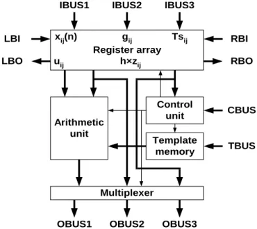
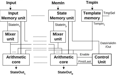
The main parts of a physical processing core in the CASTLE array architecture are the registers, the Template memory, the local control unit and the Arithmetic unit as can be seen in Figure 1.9.
Register array
Arithmetic
unit Template
memory Control
unit
Multiplexer
IBUS1 IBUS2 IBUS3
CBUS
TBUS
OBUS1 OBUS2 OBUS3
RBI LBI
LBO RBO
xij(n) uij
gij h×zij
Tsij
Figure 1.9: System-level structure of the processor core of the CASTLE architecture
The register array stores the state values, the constant values and the template select bits. These values can be loaded via IBUS1, IBUS2 and IBUS3, respectively. The template select bits are associated with every cell, which makes it possible to use space variant nearest neighborhood templates. Template values are stored in the Template memory, which can store up to 16 different templates. The template values can be loaded into the template memories via template input bus (TBUS). Four independent buses are available for inter-processor communication; these are the LBI, RBI, LBO and RBO buses. The operation of the processor is controlled by the local control unit (like the LCCU unit in CNN-UM architecture). The different operating modes can be set via the command bus (CBUS). The three main operating modes are corresponding to the accuracy of the computation: these are the 1 bit logical mode, the 6-bit resolution mode and the 12-bit resolution mode. By decreasing the accuracy the operating speed of the processor can be significantly increased and accuracy can be traded for performance.
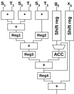
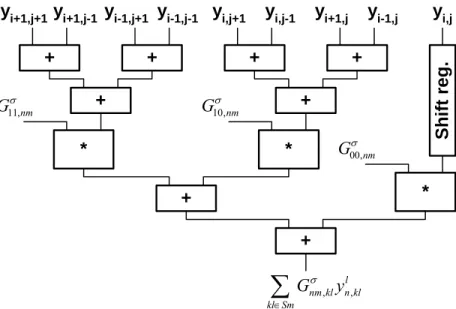
The structure of a 4-level pipeline arithmetic unit within one physical processor core is shown in Figure 1.10. It contains 3 multipliers (MULT) to multiply the state values (Si) with the corresponding template values (Ti), 3 adders to sum the partial products and two registers to store the partial and temporary results. The ACC accumulator register and ACT temporary register are master-slave registers where ACC is the master and ACT works as slave. By using 3 multipliers the template operation can be performed in a row-wise order in four steps. In the first step the gij value (Eq.(1.7)) is loaded into the ACT register. In the next cycle the first row of the state and template values is multiplied and these partial results with the contents of the ACT register are summed and stored in the ACC/ACT register. In the remainder cycles the next two template lines are processed and the final result is stored in the ACC register. After shifting, rounding and limiting (sigmoid function) the results in the [−1,+1] range the updated cell value along with the gij and template select values are sent to the next processor row. The pipeline registers are not shown in Figure 1.10, but they are located after each functional unit.
Mult Mult Mult +
ACC
ACT
Shift &
Round + +
T1 T2 T3
S1 S2 S3 g
Figure 1.10: Structure of the 4-level pipeline arithmetic unit.
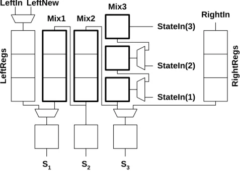
As mentioned, six physical processor elements were implemented on the CASTLE.v2 systolic processor array. The processors are arranged on a 2×3 grid in a single silicon die to improve the performance. It is depicted in Figure 1.11. If the horizontal communication
between the elements of arrays from left-, and right-side (e.g. PR_11, PR_12, PR_31, PR_32) was solved via dedicated lines similar to the inner physical processor elements (e.g.
PR_21, PR_22), the number of I/O ports would be extremely high. Therefore, decreasing the number of these bus lines two bi-directional I/O buses serve this communication in time-multiplex mode.
PR 11 PR 21 PR 31
PR 12 PR 22 PR 32
IB1_11 IB2_11 IB3_11 IB1_21 IB2_21 IB3_21 IB1_31 IB2_31 IB3_31
OB1_12 OB2_12 OB3_12 OB1_22 OB2_22 OB3_22 OB1_32 OB2_32 OB3_32
I/O LEFT I/O RIGHT
Timing and Control Unit
RESET START HALT ph1 ph2
Control Signals
Front-End Pointer Unit
FRENDIN
FRENDOUT
LASTLINE
Figure 1.11: Block level structure of CASTLE 2x3 systolic array processor with the global Timing and Control Unit and the Front-End unit
Using two-phase, non-overlapped clock signals (ph1, ph2) the global Timing and Control Unit (like a GAPU in CNN-UM) generates the register-transfer signals. The output signals of Front-End Pointer unit select the given row of processors in which the front (e.g. the first line) of the state matrix or the end (e.g. last line of the state-matrix) is under processing. The processors of the selected row doubles the top-, and bottom lines of the boundary cells with a special control sequence, therefore on the edges of the cell array zero-flux (Neumann-type) boundary condition are applied. I/O_LEFT, and I/O_RIGHT horizontal buses provide the connection towards another CASTLE chip to cascade arbitrary number of processors.
The input image is sliced-up between the columns of processors. Each line of processors do one iteration and sends the results to the processors one line below. The physical processor elements can communicate via dedicated lines between the columns in vertical direction. The whole functionality of the processors both in logical and bit-vector modes is controlled by the global Timing and Control unit, which part was implemented and verified during my research and diploma work between 2002 and 2004 at the MTA- SzTAKI [29].