Gas Analysis by Methods Depending on Thermal Conductivity
B Y E. R. WEAVER
National Bureau of Standards, Washington, D.C.
CONTENTS
Page
1. Principles of the Method 387 2. The Thermal Conductivities of Gases 390
3. Effect of Temperature on Conductivity 394 4. Effect of Pressure on Conductivity 395 5. The Conductivities of Mixtures 395 6. Construction of Analytical Cells—Early Types 397
7. Sweeping Out the Cell 399 8. Materials Used in Cells. 399 9. Interchangeability of Cells 400 10. Classification of Instruments 401
11. Measuring Circuits 402 12. Power Supply to Analytical Units 406
13. Assembly of Units and Accessories 407 14. Characteristics of the Thermal Conductivity Method 409
15. Sensitivity 412 16. Adjustment and Calibration of the Instrument 414
17. Methods of Analyzing Complex Mixtures 419 17.1. Method 1: Comparison with a Standard Gas 419
17.2. Method 2: Comparison Before and After Treatment, Usually a Chemical Reaction Which Removes or Modifies the Constituent to
Be Determined 421 17.3. Method 3: Treatment Before Analysis by Methods 1 or 2 to Make
Them Applicable 423 18. Present Status and Applications of the Method 424
19. Acknowledgments 435 References 435
1. P R I N C I P L E S O F T H E M E T H O D
A m e t h o d which d e p e n d s on t h e different conductivities of gases seems first t o h a v e been applied t o g a s analysis w i t h real success during t h e years 1 9 1 3 - 1 9 1 8 . T h e d e v e l o p m e n t of practical a p p a r a t u s a n d applica- tions took place simultaneously or n e a r l y so in G r e a t Britain, G e r m a n y , a n d t h e U n i t e d S t a t e s . A m o n g t h e n u m e r o u s workers w h o c o n t r i b u t e d t o t h e subject, a major share of credit p r o b a b l y belongs t o Koepsel ( 5 5 ) ,
387
388 Ε . R. WEAVER
who, in 1908, demonstrated t h e practicability of t h e m e t h o d a n d sug
gested various applications, a n d t o Shakespear (76), who developed t h e first commercial instrument of good construction k n o w n a n d used outside Germany. A brief review of t h e subject b y Palmer a n d W e a v e r (66) a n d a description of experiments m a d e a t t h e N a t i o n a l Bureau of S t a n d ards b y t h e m a n d their associates probably first brought t h e m e t h o d generally t o t h e attention of analysts in America. A text of 357 pages by H . A. Daynes, entitled " G a s Analysis b y M e a s u r e m e n t of T h e r m a l C o n d u c t i v i t y " (20), covered t h e subject thoroughly t o 1930 a n d will probably remain t h e best source of basic a n d historical information for s t u d e n t s of t h e m a t t e r . This text will be referred t o frequently a n d briefly as " D a y n e s . "
Shakespear's instrument was n a m e d t h e " K a t h a r o m e t e r " a n d its use is often referred t o as " t h e Shakespear m e t h o d . " Another i n s t r u m e n t is called t h e " T h e r m i c Diaferometer," b u t usually t h e instruments are constructed a n d sold for specific applications a n d are unpoetically named " g a s analyzers," "furnace controls," etc., with t h e manufacturers' or other proprietary names attached. T h e t e r m " t h e r m a l conductivity m e t h o d " is never applied t o anything else, b u t t h e "conductimetric m e t h o d " m a y mean one employing either t h e r m a l or electrical conduc
tivity. T h e terms " h o t wire m e t h o d " a n d " W h e a t stone bridge m e t h o d "
are shared equally with t h e m e t h o d depending on combustion at t h e surface of a wire, while t h e t e r m "electrical m e t h o d " is applied impar
tially to t h e three here mentioned a n d several others.
T h e principle employed is simple. If a wire enclosed in a " c e l l " is heated b y a s t e a d y electric current, its t e m p e r a t u r e increases until t h e loss of heat in one w a y or another exactly balances t h e input of electrical energy, measured b y t h e product of t h e applied voltage a n d t h e current through t h e wire. I n a cell of suitable size, m u c h t h e greater p a r t of t h e heat from t h e wire is conducted t o t h e walls of t h e cell t h r o u g h t h e gas which fills it, a n d t h e t e m p e r a t u r e of t h e wire when a balance is reached depends on how good a t h e r m a l insulator t h e gas is.
T h e hot wire, which is usually of platinum, becomes a resistance- thermometer which measures its own t e m p e r a t u r e ; b u t it differs from an ordinary resistance-thermometer in one i m p o r t a n t respect. A resistance- thermometer is normally used t o determine t h e t e m p e r a t u r e of its immediate surroundings, frequently t o a t h o u s a n d t h of a degree, a n d t h e input of electrical energy involved in making t h e measurement m u s t not change t h e t e m p e r a t u r e of t h e resistor b y even t h a t much. I n t h e gas analyzer, on t h e other hand, a r a t h e r large difference of t e m p e r a t u r e between t h e wire a n d its surroundings is desirable. Frequently this is 100°C, and as much as 250°C. has been recommended (39) in certain
GAS ANALYSIS 389 cases. T h e heating current is also t h e measuring current. Conse- quently, with a n equally good galvanometer a n d measuring circuit, it should be possible t o determine t h e t e m p e r a t u r e of t h e wire in t h e analyz- ing cell t o a very small fraction of t h e smallest change of t e m p e r a t u r e measurable with an ordinary resistance-thermometer. However, t o utilize t h e possible precision of measurement of t e m p e r a t u r e of t h e wire in a single cell, say t o 1 0 ~5° C , would require t h a t we know t h e t e m p e r a - ture of t h e cell wall as accurately, for we are not concerned with t h e t e m p e r a t u r e of t h e wire as such, b u t with t h e gradient between wire a n d cell wall which depends on t h e properties of t h e gas. E v e n if we knew t h e t e m p e r a t u r e gradient t o one p a r t in a million, t h e information would be useless unless we knew t h e i n p u t of energy t o t h e wire with equal precision.
Chiefly t o avoid t h e necessity of knowing with great accuracy t h e t e m p e r a t u r e of t h e cell a n d t h e power dissipated, conductivity 'cells are seldom used singly b u t nearly always in pairs, one of which contains a
"reference gas." Usually t h e reference gas is of known composition, as m u c h like t h a t of t h e gas t o be analyzed as is convenient. T h e two cells are arranged electrically, usually in a simple W h e a t s t o n e bridge, so t h a t t h e ratio of t h e resistance of t h e wire in one cell t o t h a t of t h e wire in t h e other cell is t h e q u a n t i t y on which t h e measurement principally depends. If t h e cells are identical a n d if t h e same gas is in both, t h e ratio of t h e resistance m u s t be unity, whatever t h e t e m p e r a t u r e of t h e cell walls a n d whatever electric power is being supplied. If t h e com- positions of t h e gases are nearly t h e same, t h e effect of t h e difference of composition measured with t h e bridge is almost independent of t h e external t e m p e r a t u r e a n d power supply. T h e greater t h e difference between t h e conductivities of gases in identical cells, t h e more seriously are t h e measurements affected b y these external conditions. Moreover, two cells never are exactly alike. Hence, although t h e comparison of two cells eliminates most of t h e trouble from external causes, if t h e high- est accuracy is desired in t h e measurements, attention m u s t always be given t o t h e control of external t e m p e r a t u r e a n d t h e electrical supply.
Since t h e only measurement we ordinarily m a k e with t h e pair of cells is t h a t of t h e ratio or other simple function of their resistances, we are limited t o a single equation a n d t o only one conclusion regarding t h e composition of t h e gas. Basically, this conclusion can only be as t o t h e proportions of t h e two constituents of a binary mixture. Fortunately, a
" b i n a r y m i x t u r e " in this case is not limited t o one containing only two chemical individuals. A n y mixture m a y be considered t o be one of t h e two components of t h e system, provided it remains of uniform composi- tion. For example, the m e t h o d is very useful in measuring t h e propor-
390 Ε . R. W E A V E R
tions of a mixture of air and carbureted water gas, although t h e air contains at least five constituents in sufficient q u a n t i t y t o affect its con
ductivity appreciably, and t h e water gas contains a dozen. B u t as long as air and gas are individually of constant composition, there is no difficulty in determining t h e ratio in which t h e y are mixed.
T h e "reference g a s " is not necessarily of known or even of constant composition. I t is frequently obtained b y making a change in t h e gas to be analyzed, such as removing one constituent, adding another, or producing a reaction between constituents already present. Conclusions are drawn as to t h e effect of t h e operation from t h e difference between t h e conductivities before and after it.
2. T H E T H E R M A L C O N D U C T I V I T I E S O F G A S E S
A knowledge of t h e thermal conductivities of gases is of interest, b u t paradoxically of little use, to t h e analyst whose instrument depends on conduction for its operation. This is t r u e because of t h e difficulty and uncertainty of making an absolute measurement of thermal conductivity.
In their review of t h e subject L a b y a n d Nelson (49) state t h a t " T h e experimental determination of t h e thermal conductivity of gases is subject to very large error. For example, t h e 19 determinations of k for air deviate on t h e average from t h e weighted m e a n . . . by 7 per cent."
Although the instruments used in what are probably t h e best measure
ments of conductivities are identical in principle with those used for analysis and m a y even have been constructed originally for t h a t purpose, it is necessary t o know m a n y things in determining conductivity t h a t need not be known in making an analysis. Among these are t h e a m o u n t s of heat lost by convection, radiation, and conduction through t h e wire, each of which is discussed in detail by Daynes, p p . 30-40. I n a cell of the t y p e principally used in the development of t h e analytical m e t h o d at the Bureau of Standards, consisting of a t u b e 1 cm. in diameter, with a straight axial wire 10-cm. long, the aggregate of these sources of heat loss a m o u n t s t o about 4 % of t h e heat transferred by conduction. Con
ductivities of gases change with t e m p e r a t u r e ; hence there is a gradient of conductivity as well as of t e m p e r a t u r e within t h e cell. W h e n mixtures are involved, a further complication is introduced by " t h e r m a l diffusion,"
as a result of which there is also a gradient of composition. T h e lighter gas is concentrated near t h e wire where its generally higher conductivity is most effective. D a y n e s ' discussion of the subject shows t h a t t h e effect of thermal diffusion m a y be more i m p o r t a n t t h a n t h e several minor methods of heat transfer. Additional difficulties in measuring conduc
tivity are t h a t of knowing exactly where within t h e cell t h e wire is
GAS ANALYSIS 391 located, t h e " i n h e r e n t e r r o r s " caused b y t h e t e m p e r a t u r e discontinuity between t h e gas and solid surfaces, and imperfect interchange of energy between t h e gas molecules a n d t h e solid surfaces.
Fortunately, these numerous obstacles t o measuring conductivity can be almost eliminated in analytical work b y empirical calibration.
T h e readings of t h e instrument when supplied with known mixtures of gases are simply recorded. I n doing this we substitute for t h e uncer- t a i n t y of measuring conductivity t h e difficulties of making known mix- tures or analyzing u n k n o w n ones b y an independent m e t h o d ; b u t experi- ence has shown t h a t t h e substitution is necessary.
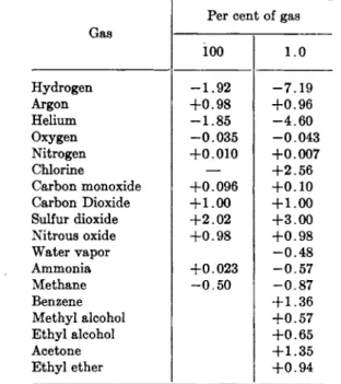
Since empirical calibration in this w a y is universally employed for analytical purposes, a knowledge of t h e conductivities of gases serves only as a general guide in planning t h e instrument a n d its use. Probably it has enough value for t h a t purpose t o justify t h e inclusion of Table I.
I n t h e preparation of t h e table, a d v a n t a g e has been t a k e n of t h e fact t h a t a selection of t h e best recorded values was m a d e b y L a b y a n d Nelson (49) and again b y D a y n e s (20), who recorded several values for m a n y of t h e gases. Their selections were considered a n d are referred t o in preference t o earlier original data, a n d their list of references is thereby reduced from 63 t o 2. T o these reviews have been added later publica- tions including summaries b y Dickins (21) a n d b y Gruss a n d Schmick (40) and a new selection of " b e s t v a l u e s " has been m a d e . T h e exact values have not enough importance in connection with analysis t o justify a discussion of t h e reasons for t h e selections, which were based as m u c h on agreement among relative as among absolute values. Sometimes a choice was based on an average of t h e d a t a of several observers; some- times on only one. Some liberty was t a k e n in reducing t h e conductivities measured at one t e m p e r a t u r e not far from 0°C. or 100°C. t o those round numbers b y t h e use of coefficients recorded in t h e literature or assumed from analogy to related compounds. Such cases are m a r k e d in t h e table b y a superscript. A close student of t h e subject should not uncritically accept t h e present a u t h o r ' s selections, b u t should consult t h e original references.
How completely t h e measurement of thermal conductivity has been isolated from its analytical use could not be better illustrated t h a n b y the fact t h a t there is no good reported value of t h e conductivity of atmospheric nitrogen (the residue after t h e removal of oxygen, carbon dioxide, and water vapor from air), yet, in t h e applications m a d e of thermal conductivity in analysis, atmospheric nitrogen is probably t h e most i m p o r t a n t of all gases, even including air itself. T h e value reported for atmospheric nitrogen in Table I was computed from t h e average composition of t h e atmosphere and t h e assumption t h a t t h e conductivities
392 Ε . R. WEAVER TABLE I
Thermal Conductivities of Gases
Formula Name Κ X 107° Rt>b #1006 References Air 583 1.00 1.00 (20, 21, 35, 36, 49,
53, 58, 59, 77, 85, 89)
H2 Hydrogen 4160 7.15 7.10 (2, 20, 21, 46, 49, 52, 53, 64, 85, 89) D2 Deuterium 3400 5.85 — (2, 52, 64, 82) He Helium 3480 5.97 5.53 (16, 20, 21, 49, 53) N2 Nitrogen 581 .996 .996 (20, 21, 37, 46, 49,
85) Atmospheric nitrogen 579 .993 .993 Computed
o2 Oxygen 589 1.013 1.014 (20, 21, 37, 49, 64, 85)
Ne Neon 1110 1.90 1.84 (16, 20, 49, 53, 89) A Argon 398 .0684 .696 (16, 20, 21, 46, 49.
53, 81) Kr Krypton 212 .363 — (10, 16, 17) Xe Xenon 124 .213 — (16)
C I , Chlorine 188 .323 — (20)
CO Carbon monoxide 563 .960 .962 (20, 21, 46, 49, 53, 81)
c o2 Carbon dioxide 352 .605 .700 (20, 21, 46, 49, 53, 56, 77, 85) NO Nitric oxide 571 .980 — (20)
S 02 Sulfur dioxide 204 .350 — (20, 21)
H2S Hydrogen sulfide 314 .538 — (20) c s2 Carbon disulfide 370 .285 — (20)
N H3 Ammonia 522 .897 1.04 (20, 21, 49, 56) H20 Water — — .775 (20)
CH4 Methane 721 1.25 1.45 (20, 49, 58, 81) C D4 Deutero methane 714 1.22 — (82)
C2He Ethane 436 .750 .970 (20, 49, 58) C2D6 Deutero ethane 370 .635 — (82)
C3Hg Propane 358 .615 .832 (58, 81) C3D8 Deutero propane 305 .523
—
(82)C4H10 n-Butane 322 .552 .744 (58)
C4H1O Isobutane 332 .569 .776 (58)
C f i H i2 n-Pentane 312 .535 .702 (20, 58)
C6H12 Isopentane 300 .515 — (20)
C6H1 4 n-Hexane 296 .508 .662 (20, 58)
C7H16 n-Heptane — — .582 (20)
C e H i2 Cyclohexane —
—
.576' (20)CeHi2 n-Hexylene 251 .431 .618 (20)
C2H4 Ethylene 419 .720 .980 (20, 49)
C2H2 Acetylene 453 .777 .900 (20)
GAS ANALYSIS 393
TABLE I.—{Continued)
Formula Name κ χ 1 07 α Rioob References CeHe Benzene .370 .583 (20)
e c u Carbon tetrachloride —
—
.288 (20)CHCla Chloroform 158 .269 .328 (20) CH2C12 Methylene dichloride 161 .276 .356 (20) CH3C1 Methyl chloride 220 .377 .530 (20) CH3Br Methyl bromide 150 .257 .350 (20) CH3I Methyl iodide 113 .194 .254 (20)
CH2F2 Freon 12 196 .344 — (77)
C2H5CI Ethyl chloride 228 .391 .540 (20) C2H6Br Ethyl bromide — .295c — (20)
C2H6I Ethyl iodide — .242c — (20)
CH4O Methyl alcohol 345 .592 .727 (20) C2HeO Ethyl alcohol — — .700 (20)
C , HeO Acetone 237 .406 .557 (20) C , H80 Methyl ethyl ether — — .772 (38)
C4H1 0O Methyl propyl ether — — .716 (38)
C4H1 0O Ethyl ether — — .747 (38)
C6H i20 Methyl butyl ether — — .664 (38)
C6H1 20 Ethyl propyl ether — — .670 (38)
C6H H O Ethyl butyl ether — — .625 (38)
CeH i40 Propyl ether — — .616 (38)
CeH i40 Isopropyl ether — — .642 (38)
C7H1 60 Propyl butyl ether — — .566 (38)
C8H i80 Butyl ether —
—
.534 (38)C2H e 0 2 Methyl acetate 161 .421 — (20)
C3H8O2 Ethyl acetate — — .543 (20)
C H6N Methylamine — .657c — (49)
C2H7N Dimethylamine — .610c — (49)
C2H7N Ethylamine — .583c — (49)
C3H9N Propylamine — .517c — (49)
C3H9N Trimethylamine — .565c — (49)
C4H n N Diethylamine — .520c — (49)
C4H n N Isobutylamine — 511c — (49) C5H1 3N w-Amylamine — .479c — (49)
C6H1 5N Di-n-propylamine — .440c — (49)
C6H1 5N Triethylamine — .457c — (49)
a Κ is the conductivity at 0°C. in cal. c m .- 8 sec.- 2 (°C. c m .- 1)- 1
b Ro and Λιοο are the ratios of the conductivities of the substance to those of air at 0° and 100°C.
c Results reduced from a slightly different temperature by means of reported temperature coefficients or coefficients deduced from a homologous series.
of m i x t u r e s of n i t r o g e n a n d a r g o n are a linear function of composition, as r e p o r t e d b y E l t z i n (24). T h e deviation from linearity i n d i c a t e d b y t h e observations of W e b e r (88) does n o t affect t h e last significant figure in t h e e s t i m a t e d v a l u e .
394 Ε . R. W E A V E R
3. E F F E C T O F T E M P E R A T U R E O N C O N D U C T I V I T Y
T h e effect of t e m p e r a t u r e on conductivity is not well established theoretically. I t has been represented b y mathematical functions only less numerous t h a n " e q u a t i o n s of s t a t e " (1, 33, 59, 86, 90). For t h e purpose of this paper only the simplest of t h e relations has been used,
kt = k0(l
+
At).In this equation kt is t h e conductivity at a n y t e m p e r a t u r e 2°C, ko is t h e conductivity at 0 ° C , and A is a constant t e m p e r a t u r e coefficient. T h e values for βχοο in Table I have been obtained in some cases by direct observation, in other cases t h e y were computed from R0 a n d observed values of A according to this equation. I n making t h e computation, it was assumed t h a t t h e value of A for air is 0.0029, t h a t is
&ioo = 1.29/co.
T h e values used for t h e mearr t e m p e r a t u r e coefficient between 0 and 100°C. for other gases can be obtained, if desired, from t h e equation
100A = _ i.
Ko
At ordinary temperatures, the values of A differ from about 0.0020 for helium to about 0.01 for such heavy vapors as benzene.
Beyond being an additional reason w h y t h e t e m p e r a t u r e of t h e analyti
cal a p p a r a t u s must be carefully controlled in accurate work, t h e fact t h a t gases do not all have the same t e m p e r a t u r e coefficients is of interest t o t h e analyst principally because t h e difference between certain pairs of gases m a y reverse its sign as t e m p e r a t u r e changes. An outstanding example is t h a t of ammonia with air or nitrogen. At low temperature, ammonia is a poorer conductor t h a n air; at high t e m p e r a t u r e a better one. Although t h e difference between t h e gases at either extreme of temperature is a d e q u a t e for t h e analysis, it is at least theoretically possible t o heat t h e wire of t h e analytical cell t o such a t e m p e r a t u r e t h a t pure ammonia could not be distinguished from air. I n most cases, t h e effect of increasing t e m p e r a t u r e is only to bring the relative conductivities of two gases more closely together.
Bolland and Melville (6) have t a k e n a d v a n t a g e of t h e differences in thermal coefficients to analyze t e r n a r y mixtures without separation by heating t h e wire t o two different temperatures, thereby obtaining two equations from which the proportions of two gases in a third can be computed.
GAS ANALYSIS 3 9 5
4 . E F F E C T O F P R E S S U R E O N C O N D U C T I V I T Y
As in t h e case of t e m p e r a t u r e effects, there is a lack of general agree- m e n t as t o t h e exact effect of changes of pressure on t h e conduction of heat from t h e wire. T h e kinetic theory, in its simpler forms at least, indicates t h a t conduction should be independent of pressures t h a t are high enough t o m a k e t h e m e a n free p a t h s of t h e molecules very small fractions of t h e distance between t h e confining walls. This is so nearly t r u e t h a t there is no general agreement as t o whether t h e observed departure from t h e rule is t o be a t t r i b u t e d t o convection a n d other interferences with t h e measurement of t r u e conductivity ( 3 4 ) or t o t h e operation of a t t r a c t i v e forces between t h e molecules a n d other things not included in t h e kinetic theory for ideal gases ( 1 1 , 8 4 ) .
T h e fact of practical importance for t h e analyst is t h a t in t h e usual instrument t h e heat transferred is nearly, b u t never quite, independent of gas pressure, so t h a t in a large variety of applications changes of barometric pressure a n d other variations not easy t o avoid are negligible;
b u t in applications requiring t h e u t m o s t available accuracy, pressures m u s t be controlled with as m u c h care as t e m p e r a t u r e a n d current.
5 . T H E C O N D U C T I V I T I E S O F M I X T U R E S
A review of t h e t h e r m a l conductivities of mixtures of gases; mainly theoretical, is given b y Daynes, p p . 1 6 - 2 5 , which is of interest t o a student of t h e subject. Like t h e conductivities of pure gases, t h e laws governing mixtures are of limited use t o t h e analyst and for t h e same reason; t h e y simply are not known accurately enough t o be of a n y use in calibrating instruments.
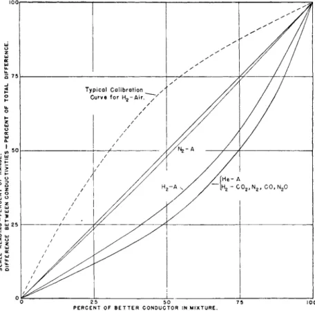
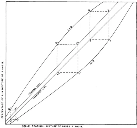
I n most cases, a plot of conductivity with respect t o t h e compositions of mixtures of two gases results in a curve t h a t is almost indistinguishable from t h e shape t a k e n b y a t h r e a d suspended from t h e two ends of t h e curve when placed at t h e same level. Different curves correspond t o different tensions of t h e string. I n Fig. 1 are shown curves d r a w n mainly from t h e d a t a of Weber ( 8 8 ) and of Ibbs and Hirst ( 4 6 ) one of which represents t h e conductivities of mixtures of hydrogen with carbon dioxide, nitrogen, carbon monoxide, a n d nitrous oxide, and of helium with argon.
On t h e scale used, a single curve represents t h e observations for all of these mixtures equally well. Separate curves represent mixtures of argon with hydrogen a n d with nitrogen. I n each case t h e linear scale used is such t h a t t h e conductivity of t h e poorer conductor of t h e two gases is assigned t h e value 0 a n d t h e conductivity of the better conductor, t h e value 1 0 0 . T h e straight line joining t h e two points would represent the composition corresponding t o each conductivity if t h e simple law
396 Ε. R. WEAVER
of mixtures were followed. T h e actual curves do not coincide with t h e calibration curves of an analytical instrument because t h e gases in t h e cells are at different t e m p e r a t u r e s a n d because t h e circuits and indicating devices are seldom or never arranged t o produce readings t h a t are strictly proportional t o conductivity. T h e y might easily mislead t h e
P E R C E NT O F B E T T E R C O N D U C T OR I N M I X T U R E.
FIG. 1. Conductivities of gas mixtures. Each point on a solid curve represents the conductivity of a mixture minus the conductivity of one component as a percent
age of the difference between the conductivities of the pure components. The broken line is a typical calibration curve of an analytical instrument.
prospective analyst, for t h e y indicate a m u c h greater change of conduc
tivity for 1 % air in hydrogen (or helium) t h a n for 1 % of t h a t gas in air.
In most analytical instruments, t h e relation of readings t o composition is just t h e reverse of this; t h e instrument is most sensitive t o changes of composition near t h a t of t h e less conducting gas, as is represented by t h e broken line which is an actual calibration curve for hydrogen in air.
G A S A N A L Y S I S 397 I n some cases of gases not too greatly different, t h e conductivities of mixtures pass t h r o u g h maxima. P r o b a b l y t h e most i m p o r t a n t cases are those of water vapor a n d a m m o n i a in mixtures with air or nitrogen.
At 8 0 ° C , t h e y show maxima a t about 20 a n d 4 0 % respectively (40).
T h e addition of either of these gases t o air increases its conductivity enough so t h a t at ordinary t e m p e r a t u r e it is quite possible t o determine t h e presence of a m m o n i a or t h e absolute h u m i d i t y of air with considerable accuracy (74). N e a r t h e maximum, small changes of composition would have no, detectable effect. However, t h e position of t h e m a x i m u m shifts with a change of t e m p e r a t u r e , a n d it is at least theoretically possible t o analyze a n y binary mixture b y selecting a favorable t e m - perature and power supply for t h e cell.
6. C O N S T R U C T I O N O F A N A L Y T I C A L C E L L S — E A R L Y T Y P E S
T h e essential p a r t of an analytical a p p a r a t u s employing thermal conductivity is t h e combination of a heating and a temperature-measuring element, which are usually b u t not always t h e same wire, in a cell cavity, t o t h e walls of which t h e h e a t is conducted t h r o u g h a gas-filled space.
For brevity, t h e t e r m " c e l l " will be used t o m e a n this entire basic device, t h e cell body, a n d its contents. Usually more t h a n one cell, as here defined, is enclosed in t h e same block of metal or other compact unit, a n d it is customary for instrument makers t o refer t o such combinations, with gas channels and essential wiring, as a cell. I n this chapter, it will be called an analytical " u n i t . "
Cells h a v e been described in which heaters a n d resistance ther- mometers were different wires or in which t h e measurement involved the use of thermocouples, bimetallic strips, or even merely t h e thermal expansion of straight tubes or wire. T h e reasons for their design have been economy, ruggedness, or measurement with direct current instru- m e n t s while heating with alternating current; b u t t h e y have found little if a n y practical use a n d will not be mentioned again.
T h e early cells of Koepsel (55) a n d of Siemens a n d Halske (78), who apparently m a d e t h e first commercial instrument, consisted of straight platinum wires in metal t u b e s of sufficient length t o minimize end- losses. Cells of this form were used in most of t h e experimental work at t h e Bureau of Standards, a n d t o some extent in commercial equipment in this country, a n d t h e y seem always t o h a v e been favored for research b y experimenters who m a d e their own a p p a r a t u s .
T h e " B u r e a u of S t a n d a r d s cell," as it was called b y Daynes, will serve as a starting point in t h e description of ceils.
T h e first cell cavities were glass t u b e s in a water b a t h ; t h e next were drilled in pairs into brass blocks, b u t single i-inch square bars were later
398 Ε. R. WEAVER
used because t h e y permitted matching t h e cells with one another t o find pairs as m u c h alike as possible. T h e square form p e r m i t t e d t h e pair of cells t o be clamped into thermal contact not detectably inferior t o cells in a single block.
A straight wire with a spring at one end was employed in preference to a coil because it was found easier for an experimenter to reproduce.
T h e diameter of t h e cell, 1 cm., was chosen as a compromise between a larger one which would give more trouble with convection and a smaller one which would be more affected b y a n y displacement of t h e wire or change in t h e dimensions of t h e cell b y corrosion or t h e collection of dust or condensate. T h e length of t h e cell, 12 cm., was chosen as about t h e m i n i m u m t h a t would permit t h e use of a wire not too delicate t o be readily handled b u t with a resistance high enough for convenient use with t h e electrical instruments available. T h e diameter of t h e wire used was about 2 mils (0.05 mm.) and its resistance about 10 ohms.
Shakespear's K a t h a r o m e t e r employed cells with a volume of only about 0.5 ml., with short helical coils of wire of very small diameter. T h e merits of t h e helix are the concentration of resistance into a shorter space and the fact t h a t the helix itself acts as t h e spring t h a t keeps t h e wire centered. Its disadvantage is t h e fact t h a t m u t u a l heating of one t u r n by another makes it difficult t o reproduce with t h e accuracy of a straight wire. Straight wires are replacing coils even in t h e instruments of the former principal user of the coiled filament, t h e Cambridge Instru
ment Co.
When t h e Charles Englehard Co. became interested in t h e production of gas analyzers, it was already manufacturing a resistance thermometer consisting of a platinum coil imbedded in t h e wall of a quartz tube.
T h e resistance thermometers, when cemented into chambers of suitable size, were found t o m a k e excellent analytical cells with which t h e recorders and other electrical equipment already used for thermometric work were quite satisfactory.
T h e active element of t h e Englehard cell is incomparably rugged, and is immune to physical or chemical change under ordinary conditions or by ordinary gases except hydrogen fluoride. I t dissipates a much larger a m o u n t of heat t h a n a cell of any other commercial t y p e , b u t a cor
respondingly larger a m o u n t of power is available for t h e operation of indicating and control mechanisms. T h e relatively large a m o u n t of power required b y t h e cell can be an a d v a n t a g e or a disadvantage, depending on the application m a d e and t h e auxiliary instruments employed. The high cost of the cell a n d the lag associated with t h e large mass of the active element are definite disadvantages.
G A S A N A L Y S I S 399
7. S W E E P I N G O U T T H E C E L L
The three cells just described and the straight-wire cells of Siemens a n d Halske are t h e only ones mentioned by D a y n e s as being in commercial use in 1930. D a y n e s regarded t h e small size of t h e Shakespear cell and t h e fact t h a t it h a d only one opening through which the gas changed b y diffusion as its distinguishing features. All others were classed as
" f l o w - t y p e " cells because t h e y have inlet a n d outlet connections a t opposite ends, a n d provision is m a d e to pass a flow of sample through t h e m .
Gas t h a t flows through a cell carries away heat a n d apparently increases conductivity. If t h e flow is not constant and t a k e n into account in calibration, it can become a source of error. I n t h e most precise work it is best t o avoid this difficulty by stopping the flow entirely while a reading is m a d e . If a continuous record or indication is required, steady flow a n d p r o m p t response are provided for b y by-passing t h e cell with a m u c h larger flow t h a n can be permitted t o enter it. T h e fraction of t h e total flow which passes t h r o u g h t h e cell is determined in p a r t b y t h e relative resistance of t h e two parallel channels and in p a r t b y convection.
Leeds a n d N o r t h r u p use a cell, devised by Peters (67), in which convec- tion alone is depended on for purging, b y connecting t h e inlet a n d outlet of t h e cell t o t h e same point of t h e sampling line. This makes t h e flow through t h e cell independent of t h a t in t h e sampling line, b u t somewhat more dependent on changes of density t h a n would be t h e case with a moderate restriction in t h e by-pass.
8. M A T E R I A L S U S E D I N C E L L S
I n t h e past 15-years a score of cells of varied construction have been placed on t h e m a r k e t b y as m a n y manufacturers. W i t h one or two exceptions, the tendency has been t o approach t h e Shakespear cell in small size and dependence on diffusion. Leeds a n d N o r t h r u p , who initially manufactured a close duplicate of t h e Bureau of S t a n d a r d s cell b u t with t h e convective circuit described above, has retained t h e approxi- m a t e form a n d size of t h e original cell b u t employs a straight glass- covered wire in a glass body. T h e primary purpose of this is, of course, t o resist corrosion. Several other manufacturers m a k e glass cells with glass-covered filaments for chlorine and other very corrosive gases, b u t employ metal cell bodies for most purposes. T h e Englehard Co. encloses its quartz-platinum resistance t h e r m o m e t e r in a quartz-glass body when corrosive conditions are anticipated. Other cell bodies h a v e been m a d e of brass, copper, aluminum, tin, lead, stainless steel, a n d brass with gold
400 Ε . R. W E A V E R
plating. Rolled metal is universally employed with t h e exception of lead, which is cast. B y far t h e majority of cells are of brass, because of t h e ease with which it can be worked, brazed, etc. Copper costs more, is harder t o machine, a n d offers few compensating advantages. Stainless steel is little used because of its cost. T h e difficulty of making secure connections t o aluminum is its greatest fault; it has t h e merit of being completely resistant t o hydrogen sulfide. Gold plating of brass, a t one time extensively employed t o prevent corrosion, has been generally abandoned because t h e coatings were often porous a n d consequently ineffective. " A c t i v e " wires of platinum, silver, tungsten, t a n t a l u m , nickel, " K o v a r , " a n d one or two other alloys h a v e been used. P l a t i n u m is still t h e most commonly employed a n d would be selected b y t h e writer for its known physical a n d chemical properties; b u t tungsten is known t o be used b y t h e General Electric C o . a n d t o some extent by t h e Chas.
Englehard Co., t a n t a l u m b y t h e Davis-Hebler Co., a n d K o v a r b y t h e Gow-Mac I n s t r u m e n t Co. D a t a which would show t h e relative merits of t h e different metals in service are lacking. T h e Cambridge I n s t r u m e n t Co. normally employs platinum wires which h a v e been gold plated t o prevent catalytic effects. Glass a n d quartz coatings, of course, serve t h e same purpose.
9. I N T E R C H A N G E A B I L I T Y O F C E L L S
T h e importance of providing cells in well-matched pairs varies with t h e application t o be m a d e of t h e m a n d their m e t h o d of calibration.
When an instrument is t o be individually calibrated, exact matching of t h e cells m a y not be necessary, particularly if t h e y are t o be used for gases of a fairly wide range of composition. T h e accurate control of t e m p e r a t u r e a n d power supply is t h e n necessary, however well t h e cells are matched, a n d when these conditions are constant, t h e calibration will be reproduced even if t h e cells are not alike. B u t when only small differences in conductivities are anticipated in t h e use of t h e instrument, t h e accuracy with which external conditions m u s t be controlled becomes proportional t o t h e difference between cells, a n d if this difference is small, elaborate controls m a y be dispensed with. W h e n a large n u m b e r of instruments is t o be m a d e for t h e same purpose, it is desirable, if possible, t o m a k e t h e m generally interchangeable, b o t h t o avoid t h e necessity of individually calibrating t h e instruments a n d to facilitate replacements.
I n this case it is not enough .to provide matched pairs; each unit should duplicate a standard. Cells are initially m a d e as m u c h alike as possible.
W h e n t h e y are connected t o form measuring bridges, an outside resistance is always adjusted t o produce a predetermined reading, usually zero, with air in both analyzing and compensating cells. This is called a " z e r o
G A S A N A L Y S I S 401 a d j u s t m e n t . " T h e electrical m e a n s of adjustment is usually retained in t h e final analyzer a n d is available for readjustment when desired. I n most cases, at t h e present time, manufacturers consider their cells inter- changeable without mechanical adjustment. I n other cases, for exacting requirements, some mechanical adjustments are considered necessary t o m a k e t h e unit independent of small changes of t e m p e r a t u r e a n d applied voltage. Harrison (42) m a d e a virtue of t h e usual fault of coiled filaments, b y providing means for adjusting t h e tension on long helical cell wires.
T h e resulting change of spacing of t h e helix permits ready compensation, which is probably t h e principal feature of t h e cells m a d e b y t h e Brown I n s t r u m e n t Co. R. H . Krueger (57) devised a short adjustable sleeve which fits over t h e lower p a r t of a cell and alters its over-all conductance.
T h e device is used in Englehard instruments. W. 0 . Hebler has described several devices for t h e purpose in t h e p a t e n t literature, b u t actually uses slight displacements of t h e position of t h e filament from t h e center of t h e cell.
10. C L A S S I F I C A T I O N O F I N S T R U M E N T S
I t will be convenient, in t h e further discussion of instruments, t o classify t h e m with respect t o function a n d accuracy. I n one group, which will be called laboratory instruments, a high degree of accuracy is needed and obtainable. Generally these instruments are used b y com- petent observers who can interpret results of varied character, apply corrections, m a k e necessary adjustments a n d calibrations, improvise accessories, and t a k e t h e time required for simple manipulation. Usu- ally, t h e manipulation needed is not more exacting or time-consuming t h a n measuring a t e m p e r a t u r e with thermocouple a n d potentiometer.
A single laboratory instrument m a y be a d a p t e d for a large variety of analyses.
I n t h e second group, which will be called industrial instruments, each has only one purpose. Generally t h e y are a t t a c h e d t o units of a manufacturing or power p l a n t ; a n d sampling lines, filters, p u m p s , con- nections, wiring, a n d indicating, recording, a n d control equipment are permanent and m a y be elaborate a n d massive. Generally less* accuracy is expected of industrial t h a n of laboratory instruments, b u t t h e y are required t o be completely automatic, t o give their results as directly as possible, and t o serve for long periods without adjustment or recalibra- tion. Cost is generally a secondary consideration.
I n t h e third class are indicators, alarms, etc., of low accuracy, a n d portable equipment such as leak detectors and devices for adjusting automobile carburetors and t h e dampers of domestic heating appliances.
T h e y m u s t be simple, with few accessories, require no trained personnel,
402 Ε . R. W E A V E R
and should be of small size a n d cost. Because of their simplicity a n d t h e large fraction of t h e m t h a t are actually portable, t h e y will be referred t o for brevity as portable instruments. There are, of course, gradations between these several types.
11. M E A S U R I N G C I R C U I T S
Almost always the measuring circuits employed in analytical work consist of some form of t h e W h e a t s t o n e bridge in which one, two, or four cells are employed. W i t h each of these there are various ways of connecting resistances or measuring instruments, so t h a t at least a score of different bridge arrangements are useful. Daynes (pp. 26-48 and 70-91) has classified a majority of t h e m and discussed their merits at greater length t h a n is possible in t h e space of this chapter.
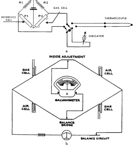
In Fig. 2 four bridges are represented. T h e y are chosen t o show t h e various alternatives rather t h a n for their relative importance among t h e arrangements in actual use. T h e bridge represented by (a) is probably the best of three or four, each with a single cell, which have been used only by research workers, mainly in t h e s t u d y of isotopes. T h e cell containing t h e gas t o be analyzed is placed in a t h e r m o s t a t with resistance C m a d e of wire of t h e same composition as is used in t h e cell. Com
pensations for changes in t h e t e m p e r a t u r e of t h e b a t h are fair; t h e y are not exact because the cell wire is at a higher t e m p e r a t u r e a n d changes its resistance b y a smaller fraction per degree of change of t e m p e r a t u r e t h a n does t h e compensating wire. There is no compensation for varia
tions of applied voltage; hence accuracy of measurement with this bridge depends on excellent thermostating a n d nearly perfect voltage control.
Bridge (b) is one of several t h a t are suitable for varied laboratory uses. T h e analytical cell A is compensated by a similar cell C which m a y contain a " s t a n d a r d " gas of predetermined composition, or a gas related t o t h a t being analyzed in a known way, for example, it m a y be t h e residue after one constituent of t h e gas in A has been absorbed b y a chemical reagent. Ri and R2 are fixed resistances referred t o as " e n d - coils" because they serve as extensions of a slide-wire S which is t h e real measuring instrument in this bridge. All measurements are m a d e with the bridge in balance; galvanometer G serves only t o show when it is balanced. T h e range of composition t h a t can be measured with a given slide-wire can be adjusted by changing s h u n t T. Decreasing t h e resist
ance of Τ increases t h e length of slide-wire t h a t corresponds t o a given change of composition, and accordingly increases t h e sensitivity of this factor in obtaining accurate readings; at t h e same time it decreases t h e sensitivity of the galvanometer. I t will be noted t h a t current from t h e
GAS ANALYSIS 403 b a t t e r y flows t h r o u g h wires A a n d C in parallel so t h a t there is exactly t h e same difference of potential across each.
I n bridge (c), which is m u c h used in industrial instruments, t h e analytical cell A and t h e compensating cell C are placed in series, so
(a) (b) 1 ι h i1
FIG. 2. Types of bridges used with analyzers.
A, Cell containing gas for analysis
C, Compensating resistance or a cell containing a gas for comparison P, Potentiometer
G, Galvanometer M, Meter
Ri, R2, Fixed resistances S, Slide-wire
T, Shunt on the slide-wire
t h a t , when t h e bridge is balanced, exactly t h e same current flows through both. Ri and R2 are fixed resistances. T h e bridge is normally unbal
anced a n d t h e voltage across it is measured with a potentiometer.
In bridge (d), four cells are used, t w o of which are filled with t h e gas to be analyzed and two with t h e gas with which it is compared. T h e
404 Ε. R. WEAVER
analysis is indicated by a deflecting electromagnetic instrument usually of t h e milliameter range of resistance a n d sensitivity. Most of t h e portable instruments use a bridge of this form.
Reasons for choosing among some of t h e alternatives will now be discussed. T h e first choice is between t h e four-cell bridge (d) a n d one of t h e two-cell bridges. T h e a d v a n t a g e of t h e four-cell bridge is t h a t , for a given applied voltage, it has twice t h e sensitivity of t h e two-cell form. A less delicate measuring instrument can therefore be used, or a lower voltage applied which saves batteries in a portable instrument.
A smaller difference between t h e temperatures of t h e wires in analyzing and compensating cells also improves compensation in some cases. T h e a d v a n t a g e of t h e two-cell bridge is t h a t it permits a greater variety a n d range of adjustments for various conditions and types of analysis. This is of particular a d v a n t a g e in t h e laboratory where t h e same bridge m a y be used for varied problems. Usually t h e four-cell bridge is m a d e u p in final form, adjusted, and calibrated b y t h e manufacturer, a n d no a t t e m p t is m a d e a t readjustment, calibrations, or repair in service. T h e entire bridge is replaced when " s e r v i c i n g " is necessary.
T h e choice between a milliameter or other deflecting instrument on the one h a n d a n d a potentiometer or a balanced bridge a n d galvanometer on t h e other, depends primarily on whether an accuracy greater t h a n t h a t with which t h e milliameter scale can be read is desired a n d whether other conditions are controlled well enough t o m a k e more accurate readings significant.
For a manually-operated laboratory instrument, t h e balanced bridge with galvanometer and slide wire possesses slight a d v a n t a g e s over t h e unbalanced bridge a n d potentiometer with respect t o simplicity, direct
ness, cost, adaptability, and n u m b e r of sources of possible error; b u t t h e margin of a d v a n t a g e is small in each respect, and for t e m p o r a r y setups t h e average laboratory is more likely t o have an available potentiometer t h a n a detached slide-wire of t h e same accuracy. W h e n this is t h e case, there should be no hesitation in using t h e potentiometer, unless work of very high accuracy is required. T h e most i m p o r t a n t item in favor of t h e balanced bridge is t h e fact t h a t it is readily m a d e to compensate for varia
tions of applied voltage a n d t h e unbalanced bridge is not, at least when direct current is used. Leeds and N o r t h r u p uses alternating-current bridges in industrial work with alternating-current potentiometers and galvanometers. Since t h e potentiometer circuit is supplied (through a transformer) with current from t h e same source as t h e bridge, t h e depend
ence of the instrument on supply voltage is reduced t o equality with t h a t of a balanced bridge.
Among t h e industrial instruments, a great m a n y of which are record-
GAS ANALYSIS 405 ing or controlling, t h e potentiometer has t w o i m p o r t a n t virtues. I t s indications are independent of t h e length or t e m p e r a t u r e of t h e connec- tions between t h e recorder a n d t h e analytical u n i t ; switching from one unit t o another can be done easily with little loss of accuracy, a n d several analyses, or b o t h analyses and temperatures, can be recorded b y a single multiple-point instrument with a single slide-wire. This is not prac- ticable with balanced bridges. Bridge (c) is, therefore, t h e preferred t y p e of two-cell bridge for industrial work. W h e n i n s t r u m e n t s are well standardized a n d factory-calibrated, four-cell units are m u c h used even when t h e potentiometer is employed for t h e measurements.
W h e t h e r t h e analyzing a n d compensating cells shall be arranged in parallel as in (b) or in series as in (c) is of minor importance. T h e series arrangement is slightly more sensitive, b u t t h e difference of sensitivity is appreciable only when there is a large difference between t h e t w o gases, a n d t h e n it is likely t o be u n i m p o r t a n t . On t h e other hand, compensa- tion for t e m p e r a t u r e a n d power supply is slightly better with t h e parallel arrangement, a n d t h e effect is greatest where it is most needed. T h e a d v a n t a g e is probably with t h e parallel arrangement for this reason. A more i m p o r t a n t a d v a n t a g e of t h e parallel arrangement in t h e case of t h e balanced bridge is t h a t a higher potential exists between t h e slide-wire a n d its contact, a n d t h e effect of variable resistance in this contact is reduced.
D a y n e s a n d others have shown t h a t good compensation between cells occurs when t h e t e m p e r a t u r e s of t h e wires are alike. I t is sometimes a convenience t o use a compensating gas t h a t differs materially from t h e gas being analyzed; for example, t o use air in a portable hydrogen-purity meter. I n such a case, good compensation with a simple bridge requires t h a t wires in t h e two cells be of different diameters if arranged in series.
If t h e y are in parallel t h e y m a y be of either different diameters or differ- ent lengths.
I n s t r u m e n t s m a d e t o produce t h e same wire-temperature in different gases are called " u n s y m m e t r i c a l " b y D a y n e s in contrast t o " s y m m e t r i - cal " units, in which analyzing a n d compensating cells are identical. T h e American tendency t o produce interchangeable p a r t s h a s m a d e t h e com- mercial production of bridges unsymmetrical through t h e use of dissimilar cells decidedly uncommon.
T h e purpose of an unsymmetrical bridge is sometimes accomplished in a symmetrical bridge, when t h e gases compared are not too dissimilar, in t h e following m a n n e r as described b y Rosecrans (73). I n a two-cell bridge, it is determined which of t h e cell wires is most susceptible t o a change of voltage a n d a manganin resistance is inserted in series sufficient t o m a k e t h e bridge a r m change b y t h e same fraction as does t h e a r m con-
406 Ε . R. W E A V E R
taining t h e other cell. T h e n t h e effect on t h e bridge of a change of ambient t e m p e r a t u r e is determined, a n d enough nickel is inserted in series or in parallel with one of t h e m a n g a n i n resistances Ri, R2, t o give it a compensating t e m p e r a t u r e coefficient.
12. P O W E R S U P P L Y T O A N A L Y T I C A L U N I T S
Bridges are usually supplied with either constant current or constant voltage. T h e a d v a n t a g e of sensitivity is with constant current, but
INSIDE A D J U S T M E NT
FIG. 3. Wiring Diagrams, a. Instrument to measure composition and temperature of flue gas. b. Exhaust gas analyzer.
there is usually sensitivity t o spare, a n d controls are sometimes simplified b y using constant voltage. T h e means of controlling currents and voltages now available would be a suitable subject for a volume of large size; those described by D a y n e s a n d particularly b y Palmer a n d Weaver
G A S A N A L Y S I S 407 are rather completely outmoded by developments in electronics, although t h e y can still be used.
P e r m a n e n t industrial installations are now almost universally designed for connection t o 60-cycle power supplies. Transformers reduce t h e voltage as m u c h as desired. I n . some cases reliance is placed on the constancy of t h e power supply, in others, automatic controls are added. Leeds a n d N o r t h r u p uses alternating current a n d alternating- current galvanometers directly with its bridges for reasons s t a t e d in t h e
115 VOLTS A - C
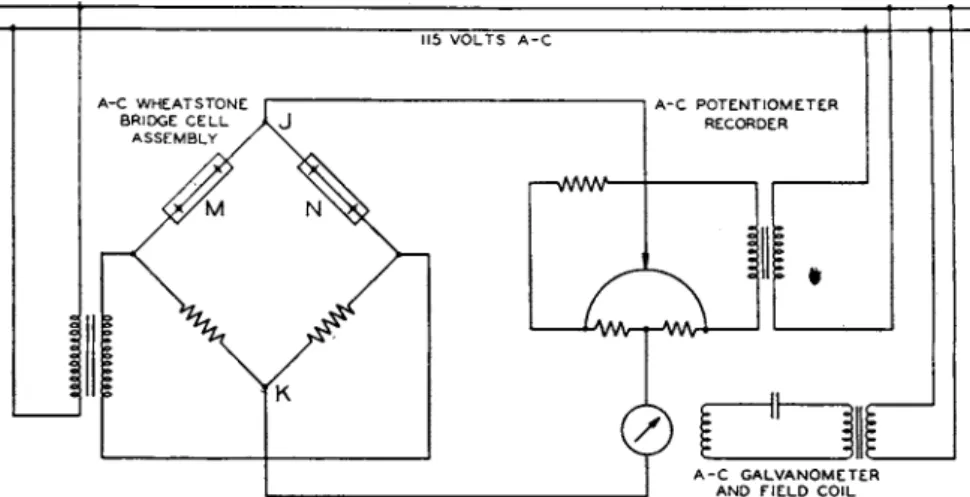
FIG. 4. Wiring diagrams of an industrial instrument with an alternating current bridge.
preceding section. Batteries are still used with m a n y instruments of t h e portable class, b u t m a n y of these i n s t r u m e n t s are also supplied with transformers a n d rectifiers a n d designed t o plug into t h e lighting circuit.
I n s t r u m e n t s of this class are usually supplied with a rheostat t o regulate t h e voltage t o t h e analytical u n i t ; a n d t h e voltage itself is measured, during adjustment, b y switching t h e milliarlcieter, with a series resistance, across t h e leads t o t h e unit.
Figures 3 t o 6 show self-explanatory wiring diagrams of several instruments. Figure 3a is t h e simple arrangement of a portable instru- m e n t for measuring t h e t e m p e r a t u r e a n d carbon dioxide content of flue gas. Figure 3b is t h e typical circuit of a four-cell bridge used as an exhaust-gas tester. Figure 4 is t h e circuit of a typical industrial instru- m e n t using a Leeds a n d N o r t h r u p alternating-current potentiometer.
13. A S S E M B L Y O F U N I T S A N D A C C E S S O R I E S
T h e two or four cells, if m a d e of metal, are usually in t h e s a m e metal block t o facilitate maintaining t h e m a t equal temperatures. Glass or
408
Ε. R. WEAVERquartz cells are fitted r a t h e r closely into h e a v y metal covers for t h e same purpose. T h e block either contains t h e gas passages or is closely a t t a c h e d t o another block which does. Insulation which carries t h e electrical connections a n d binding posts of t h e unit is rigidly a t t a c h e d t o t h e blocks b y screwing or molding in place. T h e entire assemblies of analytical units of t h e "diffusion" t y p e with four cells are usually not more t h a n
1- or 2-inches across (square or round) a n d 2- or 3-inches long. T h e industrial units of Brown, Englehard, a n d Leeds a n d N o r t h r u p are a little larger. Generally these units are placed, often with other equip
m e n t such as aspirators, filters, etc., in somewhat larger metal cases t o protect t h e cells from uneven heating b y external drafts or radiation a n d t h e wiring from mechanical damage. T h e cases are often b u t not always m a d e into air t h e r m o s t a t s with electric heating coils, bimetallic controls, and, rarely, circulating fans. For highly accurate work, t h e laboratory units are usually placed in t h e r m o s t a t e d a n d well-stirred oil b a t h s similar t o those used for other laboratory work at carefully controlled temperatures.
Sometimes t h e analytical units, with compensating cells sealed, are simply immersed in t h e gas t o be analyzed; sometimes t h e y are closely attached t o t h e wall of an a p p a r a t u s or plant unit a n d allowed t o obtain their sample b y convection or diffusion only; more frequently, samples are drawn through t h e units b y jet p u m p s , small electric p u m p s or, in t h e portable instruments, b y hand-operated rubber " a s p i r a t o r " bulbs.
I n laboratory work with limited samples, t h e cells are evacuated and allowed t o fill through suitable connections.
I n most industrial installations, t h e gases t o be analyzed are likely to contain dust or smoke which m u s t be removed because their deposition would change t h e dimensions of t h e cell. I t is almost s t a n d a r d practice t o install porous thimbles of Alundum, porcelain, or t h e like at t h e intake of t h e sampling line, renewable pads of asbestos, cellulose, or glass fibers between t h a t a n d t h e unit, a n d sometimes additional filters in t h e m o u t h s of t h e cells themselves. I t is one of t h e chief merits of cells of t h e Shakespear t y p e t h a t cell-mouth filters are provided which are especially effective because finely divided particles t h a t are carried readily by t h e gentlest flow do not diffuse appreciably a n d will not penetrate a filter where there is no flow.
W a t e r vapor is a n almost universal constituent of industrial gas mix
tures, a n d while it is sometimes t o be determined as significant, its a m o u n t is more often t h e result of conditions of little interest to the analyst. I t s variations t e n d t o mask those of more i m p o r t a n t gases a n d in most cases are t o be eliminated if possible. Two ways of doing this are employed with nearly equal frequency. One is t o remove t h e