airplanes
Article in Analecta Technica Szegedinensia · December 2019
DOI: 10.14232/analecta.2019.2.65-76
CITATIONS
0
READS
104 6 authors, including:
Some of the authors of this publication are also working on these related projects:
Composite testView project
Material tests, compositesView project László Gogolák
Visoka tehnička škola strukovnih studija 14PUBLICATIONS 96CITATIONS
SEE PROFILE
Peter Szuchy University of Szeged 8PUBLICATIONS 1CITATION
SEE PROFILE
István Bíró University of Szeged 55PUBLICATIONS 185CITATIONS
SEE PROFILE
József Sárosi University of Szeged 55PUBLICATIONS 283CITATIONS
SEE PROFILE
POSSIBILITIES OF OPTIMIZING FUEL CONSUMPTION IN HYBRID AND ELECTRONIC AIRPLANES
László Gogolák, Sándor Csikós, Tamás Molnár, Péter Szuchy, István Bíró, József Sárosi Department of Technology, Faculty of Engineering,University of Szeged, Mars tér 7. 6724, Szeged, Hungary
e-mail: sarosi@mk.u-szeged.hu
ABSTRACT
The automotive industry was always characterized by innovation and the use of cutting edge technology. Daily we can see vehicles packed with technological advancements. The main focus of the current technological trend is electric drives. With the rise in popularity of electric cars more types of vehicles are adapting electric drives. In the case of airplanes the standards are higher than in the case of cars so the emphasis of research and innovation is greater. This paper presents a list of the challenges electric aircrafts face and their potential solutions. Currently many of these problems currently only have partial solutions if any. There is also a comparison between the properties of materials used and the expectations for hybrid aircraft. A comprehensive model was created taking into account the criteria set for hybrid and electric aircraft. With the aid of the model the effect of the most important components on efficiency can be assessed.
Keywords: hybrid and electronic airplanes, fuel consumption, optimization model
1. INTRODUCTION
With the increasing of the greenhouse effect even more concern is placed on the reduction of harmful emissions in air travel. Based on the Strategic Research & Innovation Agenda (SRIA)[1] of the Advisory Council for Aeronautics Research in Europe (ACARE) the International Air Transport Association (IATA)[2] and the European Commission (EC)[3] announced long-term environmental protection goals.
The plans may seem ambitious looking at the technologies currently being used.
The main focus is on the reduction of the energy needed for propulsion. The goal is a 30% decrease in the needed propulsion and power by 2035. A 70% decrease in carbon dioxide emission is the goal by 2050.
By 2020 an estimated 20% decrease is expected in the energy needed for propulsion and power compared to the reference data from 2000. The efficiency of the drive holds the key to the greatest reduction in carbon dioxide emissions [4].
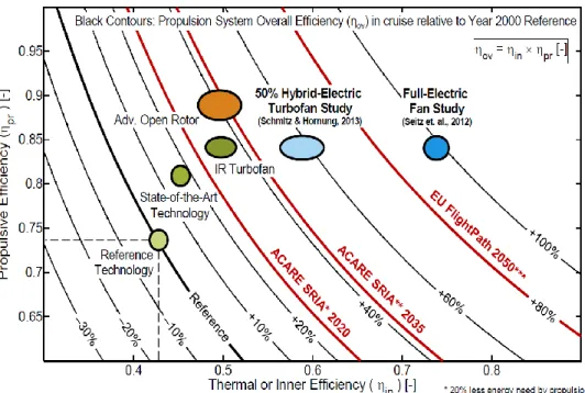
Figure 1 shows the efficiency of currently used drives and the goals set by the strategy. Figure 1 shows the total overall efficiency of the airplanes drive during flight ηov (overall efficiency) compared to the reference year of 2000. The graph shows two types of efficiencies the product of the two gives the aforementioned overall efficiency. The vertical axis shows the efficiency of the propelling force ηpr (propulsive efficiency) while the horizontal axis shows the internal or thermal efficiency ηin.
Figure 1. Propulsion systems overall efficiency
The graph shows that the goal of ACARE by 2035 is to increase total efficiency to 43%, while setting an 80% increase by 2050, which can be achieved by improving both types of efficiency. The current state of the art engines efficiency is 15% above the efficiency of the year 2000 baseline model. Improving on the advanced gas turbine based concept [4] we can expect an efficiency of about 50% or more which fulfils the efficiency goals set by 2020. The greatest increase in propulsive efficiency can be expected from the Open Rotor (OR) and the Turbofan drives.
The limits of the drives can be exceeded with the introduction of electrical energy. Figure 1. shows the efficiency of hybrid and fully electrically driven air funnel propeller drives [6][7]. From the studies we can see that electrifying the turbo drives efficiency of 50% is expected to reach the efficiency goals of 2035, while converting to a fully electric drive is expected to yield an efficiency of nearly 100%.
2. HYBRID ARCHITECTURES AND HYBRIDIZATION
To increase efficiency and lower fuel consumption it is paramount to choose an appropriate drive architecture. Electric drives can be characterized with drive configurations, these configurations share a few key components such as motor, generator, battery and energy converter, in short
power management
and configuration (PMAD) systems. Studies usually separate electric drives into three main groups [5][8]: All electric propulsion
Turboelectric propulsion
Hybrid electric propulsion
The mentioned solutions mostly differ in efficiency, carbon dioxide emission and noise pollution.
3. ALL ELECTRIC PROPULSION
In the case of all electric propulsion all energy required is stored in the battery. Total efficiency ηov is almost 90% [9] and since in this case we don’t need conventional engines only electric carbon dioxide emission can approach nearly 0. Another important aspect is the noise level since with the absence of combustion noise pollution ceases.
Power Converter
Electric Motor
Figure 2. Block diagram of all electric propulsion system
4. TURBOELECTRIC PROPULSION
Turboelectric systems do not rely on batteries to store electrical energy. The total turbo electric system is made up of a turboshaft motor with turns a generator which in turn spins the electric motors that move the propellers (Figure 3a). In a partial turboelectric system both engines are used for propulsion. Meaning the turboshaft motor only uses a portion of its output to drives the generator (Figure 3b). The most important aspect of this type of drive is that the turboshaft motors can be operated in their optimal efficiency range regardless of the needed torque.
Power Converter TurboShaft
Electric Motor Generator
Figure 3a. Block diagram of total turboelectric propulsion system
Power Converter TurboFan
Electric Motor Generator
Figure 3b. Block diagram of partial turboelectric propulsion system
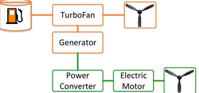
5. HYBRID ELECTRIC PROPULSION
Hybrid drive systems come in a variety of architectures. Most commonly used ones are the series hybrid and parallel hybrid architectures [10]. Figure 4 shows a series powertrain which is the simplest one. The shaft of the propeller is spun by the electric motor. Turboshaft motors spin the generators and provide energy to the battery or the electric motors. This means that the gas turbine can run at its optimal range thus lowering fuel consumption and the exhaust of harmful burn products.
Figure 4. Block diagram of series hybrid propulsion system
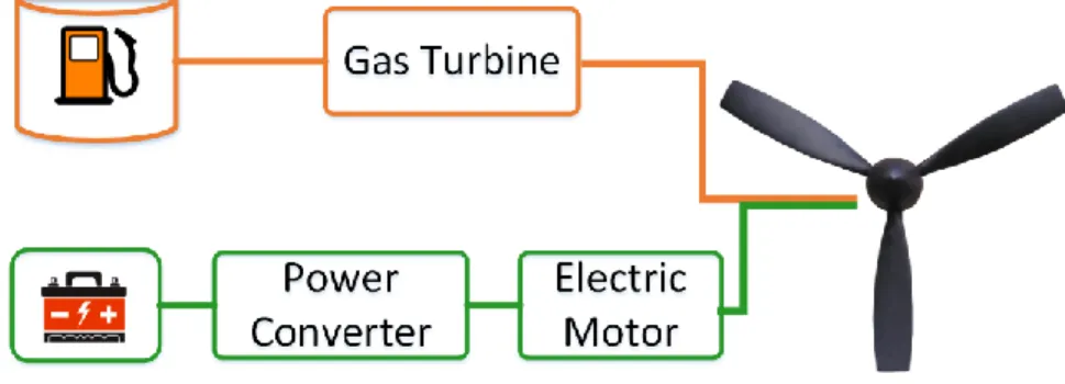
A further advantage is that a typical gas turbine can be smaller to meet the average energy needs. To meet the demands of the needed power the size of electric motors and batteries has to be larger. taking into account the weight of the generator this means a substantial increase in weight compared to the parallel architecture [11]. For ground vehicles this is not such a problem, but for airplanes this is an important question. Another drawback is the power loss due to power conversion since we convert the mechanical energy of the gas turbines to electric energy and then back again to mechanical with the electric motors to drive the propellers there are substantial losses [12]. In the case of parallel hybrid configurations mechanical and electric power is funnelled in parallel to the gearbox as shown in Figure 5.
Figure 5. Block diagram of parallel hybrid propulsion system
An advantage of this architecture is that there are only two motors with their own power sources. Because of this we save on weight which in the case of air travel is important. A further advantage could be that the two separate drives increase reliability. Perhaps the greatest disadvantage is the increase of complexity of the drive and the controller since the energy required for propulsion comes from two sources these have to work together.
The most common strategy in the case of hybrid electric cars is that the gas turbine works all the time with constant load where it’s most effective. The electric motor is used when additional power is needed (like in the case of takeoff). If the energy needed for the propeller is less than what is provided by the gas turbine the remainder can be used to recharge the battery, this is achieved by using the motor as a generator. The combining of the series and parallel architectures brought the series-parallel hybrid and complex hybrid architectures. These architectures combine the advantages and drawbacks of both series and parallel architectures. They are unusable for flying mostly because of their weight.
6. MEASURE OF HYBRIDIZATION
When having more than one drive in a vehicle the tuning and handling of them becomes a real challenge.
In the case of hybrid vehicles the electric drive needs to connect to the system so that it provides maximum efficiency. Because of this some new variables come into play [13]. One of the key variables is the measure of energy hybridization which is the ratio of the electric energy to the total energy.
𝐻𝐸=𝐸𝑏𝑎𝑡
𝐸𝑡𝑜𝑡 = 𝐸𝑏𝑎𝑡
𝐸𝑏𝑎𝑡+ 𝐸𝑓 (1)
Where 𝐸𝑏𝑎𝑡 is electrical energy and 𝐸𝑓 is the energy coming from the fuel. The measure of energy hybridization is not an ideal indicator since the specific energy of the fuel is much greater that the specific energy of the battery while the efficiency of electric drives is far greater than the efficiency of gas turbines.
Because of this reason we use the power hybridization indicator as well [10].
𝐻𝑃= 𝑃𝑒𝑙
𝑃𝑡𝑜𝑡= 𝑃𝑒𝑙
𝑃𝑒𝑙+ 𝑃𝑡ℎ (2)
W
here 𝑃𝑒𝑙 is the power of the electric motor and 𝑃𝑡ℎ is the power of the gas turbine. For conventional airplanes the measure of hybridization is 0 since all the energy comes from theburning of fuel:
𝐻
𝐸= 0
and 𝐻𝑃= 0. In the case of turbo-electric airplanes all energy is all propulsion is from electric motors that are powered by gas turbines giving us 𝐻𝐸= 0 and 𝐻𝑃= 1. In the case of fully electric airplanes we have 𝐻𝐸= 1 and 𝐻𝑃= 1. This means that all energy is from the battery and all propulsion is from electric motors. In practice this indicator is not always applicable since an airplane with a large electric motor that is used sparsely gives a large power hybridization value while in reality during flight it’s only hybrid for a short time.For this reason another parameter the produced power ratio [14] (Φ) is used which is the ratio of the power exerted by the electric motor and all the power exerted during flight.
Φ = 𝐸𝑒𝑚𝑡𝑜𝑡
𝐸𝑝𝑜𝑤𝑡𝑜𝑡 (3)
In the case of a traditional airplane Φ=0 while at a fully electric airplane Φ=1. A further example Φ=0.4 means 40% of the energy for flight came from the electric drive and 60% from the gasturbines.
7. ENERGY STORAGE
Energy storage is the most crucial criteria when designing a hybrid airplane. Traditional aircraft use fuel with a far larger specific energy (12000-13000 Wh/kg) [15] than in the case of batteries. The specific energy of batteries needs to increase in accordance with economic and ecological expectations. Figure 6 shows a Ragone diagram which is used to describe the current levels of batteries where the specific power and energy are shown on a logarithmic scale. An optimal combination is where both are fairly high.
Figure 6. Ragone diagram for specific Energy and Specific Power [15]
8. LI-ION AND LI-POLY BATTERIES
Lithium-ion and Lithium-polymer batteries are the most used batteries on the market thanks to the ideal placement of both characteristics (Figure 6.). Lithium-polymer technology has a similar characteristic. The power of the Lithium batteries is determined by the materials used for the electrodes. The state of the art batteries positive electrode is made of Lithium-metal-oxide (mostly cobalt and manganese) while the negative electrode is made of graphite, these batteries have a specific energy of 300 Wh/kg and have a specific power of less than 100 W/kg. These values are not enough for a typical flight. For example a Tesla Model S P85 electric car has a Li-ion ESD (Energy Storage Device) which has a maximum continuous power of 311W and a total stored energy of 85 kWh. The mass of the battery is 540 kg so it has a specific power density of 575 W/kg and a specific energy density of 157 Wh/kg.
In the studies made by the Safran company [17] they show that a smaller airplane would need a battery with a specific energy density of 500 Wh/kg while a bigger passenger carrier would need between 600 and 750 Wh/kg. The above mentioned Li-ion and Li-polymer batteries provide a good basis for the electric and hybrid cars of our age, but are inadequate for hybrid airplanes.
9. LI-AIR BATTERIES
Lithium-Air batteries hold a lot of promise. This technology has a theoretical specific energy of about 11500 Wh/kg which is close to the specific energy of gasoline. They have a major flaw that needs to be solved first which is their short lifespan. After the third charging cycle the capacity of the battery is greatly reduced, making this technology unsuitable for aircraft use.
10. LI-S BATTERIES
Currently Lithium-Sulphur batteries are the most promising energy storage devices [19], because compared to Li-ion batteries they have a large specific energy. The theoretical maximum is 2567 Wh/kg at 2.2 volts.
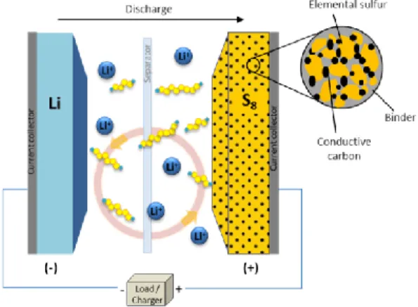
Currently the OxisEnergy company [20] sells these type of batteries which have a specific power of 300 Wh/kg and plan to double this value in the next five years. These batteries are characterized by a Lithium anode and a Sulphur cathode as seen on Figure 7.
Figure 7. Lithium-Sulphur battery cell
In the discharge process the lithium reacts with the sulphur to become Li2S, which in the process of recharging breaks up into its components. The problem with Li-S batteries is their lifetime currently they last for 500-1000 charging cycles, the manufacturer plans to increase this to 1500-2500 cycles in the next few years. On a positive note they have a low production cost of about 250 euros/kWh compared to Li-ion which have a price of 475 euros/kWh.
Following the trend of the Li-S batteries by 2021 we can expect a specific energy of about 500 Wh/kg, 650 Wh/kg by 2030 and 1000 Wh/kg by 2040. These values are adequate for use in hybrid airplanes.
11. ELECTRIC MOTORS
The second main pillar of hybrid and electric vehicles is the electric motor. Thanks to electric and hybrid cars these have also advanced quite a bit. More power with less loss, weight and size these are the most important criteria for flying applications. The Siemens company has made excellent headway in this field thanks to its intense research strategy [21]. These motors have an efficiency
of 95% and
are quite light, their power density (Wsp) exceeds 6 kW/kg. It can be easily redesigned for smaller or larger applications, making it ideal for large or small aircraft.The following criteria need to be taken into consideration:
The use of high performance magnetic materials for higher torque density
High performance cooling to increase the efficiency of the motor
The optimization of passive elements to make use of advanced manufacturing techniques such as 3D printing
Optimizing the rpm range of the motor ideally removing the need for a gearbox
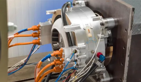
Taking these criteria into consideration Siemens made their SP260D induction motor (Figure 8.) which has a maximum continuous power of 260 kW at 2500 rpm and a total mass of 50 kg. The power density of this motor is at least 5 kW/kg. This motor has been installed and tested on the Extra 330 LE airplane.
Figure 8. Siemens SP260D electromotor
In future automotive and aircraft applications the so called high temperature superconducting (HTS) motors can be used. These motors cooled by liquid nitrogen can have an internal resistance of 0 thus having high power density. Their only drawback is that they need constant cooling which uses mostly liquid nitrogen. Currently available HTS motors fall short of expectations having 30 kW-s of power with a 110 kg engine [22]. Their power falls short compared to the SP260D, but HTS motors are relatively new and research shows that a power density of 20 kW/kg is possible.
12. THE MATERIAL AND STRUCTURE OF AN AIRPLANE
Other than the mass of the above mentioned motor and battery one of the most important parameters is the mass of the fuselage and its structure.
13. THE MATERIAL OF AN AIRPLANE
Modern airplanes use carbon and glass reinforced composites [24]. The two components of the composites are the matrix and the reinforcement. The composites were developed for combining the benefits of the different materials’ advantageous physical parameters. The first “modern” composite (used even today) was the textile-bakelite that is a phenol formaldehyde resin enhanced by textile fibres. The resin is a really rigid, frangible and weak plastic and only the enchantment with natural textile fibres made it suitable for wider industrial applications. The first composite applied in aircraft industry in bigger amount was a one-
direction strip named GORDON AEROLITE developed by Aero Research Ltd. that was an untwisted line string impregnated by phenol resin in the ‘30s. The next step was the “marriage” of the high strength fibre glass and the polyester resin that was used first in 1943 for the rear part of the fuselage of a trainer plane (Vultee XBT-16) made in the USA with a honeycomb structure sandwich panel. In the aircraft industry appeared the epoxy-resin matrix materials that were first reinforced with fibre glass then carbon-, graphite- or aramid-fibres, boron-fibres, ceramic fibres or the combinations of them [25].
Currently polyimide and bismaleimide basic thermosetting resins and thermoplastics are more significantly used for bedding the reinforcing fibres due to their higher temperature tolerance. Nowadays the modern composite materials are widely used for the airframe structure of the lightweight sport and general purpose airplanes and of the new generation military attack and fighter planes and helicopters. The reinforcing fibres of the composite materials have high tensile strengths and high Young-modulus, but their density is much lower than of the metals and in addition their structure can be anisotropic (generally orthotropic). In the workshop of the University of Szeged, Faculty of Engineering, Department of Technology standard specimens were produced and the composition of metals were investigated (Figure 9.).
Figure 9. Investigation of a lightweight, fixed-wing airplane built for sport purpose [24]
14. THE STRUCTURE OF THE AIRPLANE
Several have been developed in the history of aircraft design. With the advance of airplanes the position of the wings, engines, rudders changes even to this day. The configuration of gas turbine aircraft is vastly different from hybrid and electric aircrafts and requires different considerations from the designer. Several studies were conducted to explore which configurations are most optimal for hybrid and electric aircraft [23]. The result of these studies present 35 possible configuration which merit further research (Figure 10.).
Figure 9. Illustration of 15 out of a total of 35 proposed concepts
15. DEVELOPING AN OPTIMIZATION MODEL
The topics discussed in previous subchapters all contribute to the optimization of hybrid and electric airplanes. Several other parts could also contribute to the optimization process (such as drive electronics, choosing the optimal cable size etc.), however we will omit these. During our research we aimed to create a model that takes into account the most important facets of optimizing the efficiency of an aircraft. These facets are: the architecture of the drive, energy storage, electric motor selection, the structure and material of the aircraft. These are the facets that impact the basic manoeuvres and thus the flight duration, quality of flight, safety, fuel consumption and efficiency (Figure 10.).
Figure 10. Illustration of 15 out of a total of 35 proposed concepts
In the modelling of fuel consumption usually only 5 base manoeuvres are taken into consideration [15]:
Take-off: this is simulated to have a realistic power requirement and energy consumption, by considering the two phases of ground run and airborne acceleration.
Climb: the aircraft climbs from airport altitude to cruise altitude and accelerates from take-off to cruise speed.
Cruise: this phase is carried out at a constant altitude and true airspeed.
Descent: the dual of climb phase, it starts at cruise speed and altitude and ends at loiter speed and altitude, using the same strategy considered for climb.
Loiter: this phase is considered both for possible deviations and for actual hold above the destination airport.
With the optimization of these base manoeuvres we can impact flight time, safety and fuel consumption.
The hypothetical model tries to optimize by taking into account in a simplified way the effects of the base components on hybrid and electric airplanes fuel consumption. Individually it wouldn’t try to classify their effects since can be several future solutions which effects on fuel consumption are unknown.
16. CONCLUSION
With the rise in the greenhouse effect stricter standards are placed on aircrafts. The plans laid out by the International Air Transport Association and the European Commission has set ambitious goals. We checked for possibilities to meet these expectations. The state of the art and future trends of the most crucial elements of the aircraft have been examined. Their effect on fuel consumption in electric and hybrid aircraft was examined. The data reviled that several components currently have the ability to be used in electric or hybrid aircraft, yet many still need further improvements. Currently the batteries capacity needs the greatest improvement. Several advances were presented sadly they currently do not meet the set requirements to be used. We presented our findings in a model which shows the effect of these components on an aircraft’s fuel consumption. This model may only be partial but serves as a baseline for further studies.
17. ACKNOWLEDGEMENTS
The project has been supported by the European Union, co-financed by the European Social Fund. EFOP- 3.6.1-16-2016-00014. Authors are thankful for it.
REFERENCES
[1] Advisory Council for Aeronautics Research in Europe. Strategic Research Agenda, Volume I, October 2002.
[2] International Air Transport Association, “IATA Calls for a Zero Emissions Future”, Press Release No.21, 4 June 2007, published in http://www.iata.org, cited: 30 May 2011.
[3] European Commission, “Flightpath 2050: Europe’s Vision for Aviation”, Report of the High Level Group on Aviation Research, Publications Office of the European Union, Luxembourg, 2011
[4] Seitz, Arne, Askin T. Isikveren, and Mirko Hornung. "Pre-concept performance investigation of electrically powered aero-propulsion systems." 49th AIAA/ASME/SAE/ASEE Joint PropulsionConference. 2013. 3608.
[5] Casalino Lorenzo; Zafferetti Mirko. Turbo-Electric propulsion system of a high bypass-ratio turbofan engine for civil liner aircraft. 2018.
[6] Seitz, A., Schmitz, O., Isikveren, A.T., Hornung, M., “Electrically Powered Propulsion: Comparison and Contrast to Gas Turbines”, Paper No. 1358, Deutscher Luft- und Raumfahrtkongress 2012, Berlin, September 2012
[7] Schmitz O., Hornung M. “Unified Application Propulsion System Performance Metrics”, GT2013- 95724 in Proceedings of ASME Turbo Expo, San Antonio, Texas, 3-7 June, 2013.
[8] Aigner, B., Nollmann, M., & Stumpf, E. Design of a hybrid electric proupulsion system within a preliminary aircraft design software environment. Deutscher Luft- und Raumfahrtkongress 2018 [9] National Academies of Sciences, Engineering, and Medicine: Commercial Aircraft Propulsion and
Energy Systems Research. Reducing Global CarbonEmissions, Washington, D.C: The National Academies Press, ISBN 978-0-309-44096-7, 2016.
[10] Van Bogaert, Joris. "Assessment of Potential Fuel Saving Benefits of Hybrid-Electric Regional Aircraft." (2015).
[11] F. Christian and A. R. Paul, Design of hybrid-electric propulsion systems for light aircraft, in 14th AIAA Aviation Technology, Integration, and Operations Conference, AIAA Aviation (American Institute of Aeronautics and Astronautics, 2014) doi:10.2514/6.2014-3008.
[12] J. Y.Hung and L. F. Gonzalez,On parallel hybrid-electric propulsion systemfor unmanned aerial vehicles, Progress in Aerospace Sciences 51, 1 (2012).
[13] Joris Van Bogaert, Assessment of Potential Fuel Saving Benefits of Hybrid-Electric Regional Aircraft, TUDelft, Delft, 2015.
[14] R. Singh, A. T. Isikveren, S. Kaiser, C. Pornet, and P. C. Vratny, Pre-design strategies and sizing techniques for dual-energy aircraft, Aircraft Engineering and Aerospace Technology 86, 525 (2014).
[15] Rossi, Niccolò. "Conceptual design of hybrid-electric aircraft." (2018).
[16] D.V. Ragone, Review of Battery Systems for Electrically Powered Vehicles, SAE Technical Paper, 1968.
[17] A.T. Isikveren, C. Pornet, Y. Fefermann, C. Maury, Hybrid-Electric Motive Power Systems for Commuter Transport Applications, 30th Congress of the International Council of the Aeronautical Sciences, September 2016.
[18] P. Birke, Electric Battery, Actual and future Battery Technology Trends, Continental Powertrain Division, May 2010.
[19] Fraunhofer Institute for Systems and Innovation research, Technology Roadmap Energy Storage for Electric Mobility 2030, BMBF Innovationsallianz, 2015.
[20] Oxis Energy, https://oxisenergy.com/products/.
[21] Siemens, Electric propulsion components with high power densities for aviation, Transformative Vertical Flight Workshop, March 2015.
[22] T. Shinzato, S. Arakawa, H. Oyama, H. Saka, T. Hayasaki, Development of High-Temperature Superconducting Motor for Automobiles, SEI Technical Review 75, October 2012
[23] Hoogreef, M., Vos, R., de Vries, R., & Veldhuis, L. L. (2019). Conceptual Assessment of Hybrid Electric Aircraft with Distributed Propulsion and Boosted Turbofans. In AIAA Scitech 2019 Forum (p.
1807).
[24] Molnár, T. ; Szuchy, P. ; Csikós, S. ; Gogolák, L. ; Bíró, I. ; Sárosi, J. Material tests and analysis of aircraft materials annals of faculty of engineering hunedoara - international journal of engineering 17 : 1 pp. 95-100. , 6 p. (2019) Journal Article/Article (Journal Article)/Scientific
[25] Csikós S. ; Molnár T. ; Szuchy P. ; Gogolák L. ; Bíró, I. ; Sárosi, J. Vibrational tests and analysis on materials used in aircraft Review of Faculty of Engineering Analecta Technica Szegedinensia 12 : 2 pp. 32-36. , 5 p. (2018)
![Figure 6. Ragone diagram for specific Energy and Specific Power [15]](https://thumb-eu.123doks.com/thumbv2/9dokorg/1285966.102819/7.774.95.672.273.696/figure-ragone-diagram-specific-energy-specific-power.webp)
![Figure 9. Investigation of a lightweight, fixed-wing airplane built for sport purpose [24]](https://thumb-eu.123doks.com/thumbv2/9dokorg/1285966.102819/10.774.218.558.415.700/figure-investigation-lightweight-fixed-airplane-built-sport-purpose.webp)

