A Novel Test Method to Induce Bi-axial Stress States in Thin-ply Carbon Composites Under Combined Longitudinal Tension and
Transverse Compression
TAMAS REV, GERGELY CZÉL and MICHAEL R. WISNOM
ABSTRACT
A novel test configuration has been developed to induce combined stress-states of in- plane longitudinal tension and transverse compression in unidirectional (UD) composite layers. Two different multi-directional laminates have been designed incorporating UD carbon/epoxy plies embedded in angle-ply blocks of the same material. The scissoring deformation of the angle-plies induces compression in the central UD layers when the composite is strained in the 0° fibre direction. The amount of transverse compressive stress is determined through an inverse identification method from the measured surface strains of the laminates. Despite the large in-plane transverse compressive strain generated, there is only about 9% drop in the failure strain of the laminates when compared to the baseline failure strain of the UD carbon/epoxy material.
INTRODUCTION
Composite materials play a leading role in the development of today’s advanced engineering structures due to their outstanding properties. To meet the ever-increasing demand of industries such as aerospace, automotive and civil engineering, it is crucial to be able to determine the strength of composite materials in the most accurate way possible, especially under multi-axial loading, to establish their behavior in realistic operation conditions. Consequently, industries can ensure a safer operation in service and achieve significant reduction in costs at the same time.
Many failure criteria have been proposed and utilized to tackle the problem of predicting the failure of composite materials.
_____________
Tamas Rev, Bristol Composites Institute (ACCIS), University of Bristol, Queens Building, University Walk, Bristol, BS8 1TR, United Kingdom.
Dr. Gergely Czél, Department of Polymer Engineering, Faculty of Mechanical Engineering, Budapest University of Technology and Economics, Műegyetem rkp. 3., H-1111 Budapest, Hungary.
Prof. Michael R. Wisnom, Bristol Composites Institute (ACCIS), University of Bristol, Queens Building, University Walk, Bristol, BS8 1TR, United Kingdom.
The difficulty in obtaining reliable experimental data for multi-axial and combined loadings makes it hard to validate predictions of the response of such fibrous material [1]. Accurately determining the fundamental mechanical properties of composite laminates such as failure strain or failure stress is still a great challenge [2]. For instance, the experimental strength measurements of unidirectional (UD) carbon/epoxy composites are often affected by stress concentrations at the end-tab regions of the specimens in tensile tests. In these cases, a significant knock-down in their measured strengths may be observed, premature failure can occur and notably lower measured strains than the expected ultimate failure strain of the fibre can be measured [3].
In this paper, a novel approach based on a thin-ply laminate of unidirectional (UD) and angle-plies is presented. The bi-axial stress state in the 0° plies of longitudinal tension and transverse compression is indirectly applied in a tensile test set-up. In this method, the contraction of the angle-plies induces compression in the central UD layers when the composite is strained in the longitudinal direction.
MATERIAL AND CONFIGURATION DESIGN Material
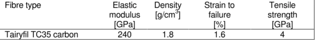
The material considered for design and used in the experiments was a thin-ply TC35 carbon fibre (Formosa Plastics) supplied by SK Chemicals. The K51 epoxy resin system was a 125°C curing toughened system. Basic properties of the applied fibre and prepreg system can be found in Table I and Table II respectively.
Table I. Fibre properties of the applied unidirectional prepreg based on manufacturers data.
Fibre type Elastic
modulus [GPa]
Density
[g/cm3] Strain to failure
[%]
Tensile strength [GPa]
Tairyfil TC35 carbon 240 1.8 1.6 4
Table II.Cured ply properties of the applied unidirectional prepreg.
Prepreg type Areal
density1 [g/m2]
Cured ply thickness1
[µm]
Fibre volume fraction1
[%]
Initial elastic modulus1
[GPa]
Tensile strain to failure1
[%]
TC35 carbon/epoxy 21 30 39 95.3 1.78 [4]
1Based on measurements
Design
The design of the specimens incorporated the following three criteria:
(i) The laminate configuration needs to be designed in a way that variable levels of transverse compressive stress are indirectly applied, while the laminate is strained in the longitudinal direction of the fibres
(ii) The design of the laminates allows for an overall failure mechanism of fibre failure in the composite
(iii) The design of the laminates allows for avoiding any premature edge delamination
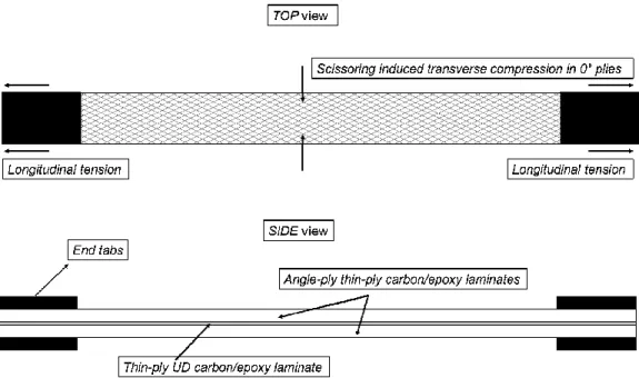
The top and side view schematics of a typical specimen are illustrated in Figure 1.
Figure 1. A top and side view schematic illustration of the thin-ply UD laminate embedded in the thin-ply angle-ply blocks.
With regard to the criteria mentioned above, the key influencing parameters for the amount of transverse compression generated are the angle and the relative thickness of the outer angle-ply blocks. There is a Poisson’s ratio mismatch between the angle-ply blocks and the UD laminate. By maximizing this mismatch and choosing an optimum angle, the transverse compression can also be maximized in the central layers.
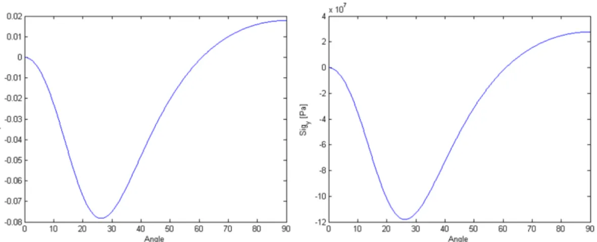
Besides, increasing the number of angle-ply pairs in the blocks increases the amount of transverse stresses put on the central UD layers. The optimization was carried out in MATLAB software using Classical Laminate Theory (CLT) assuming a plane stress state for the composite laminates. An illustration of varying amounts of transverse stresses and transverse to longitudinal stress ratios arising in the central 0° layers as a function of the angle of the angle-ply blocks is shown in Figure 2. The applied strain for the generated curves was 1.6 %.
Another parameter is the absolute thickness of the central UD layers that plays an important role in ensuring that any hybrid effect is avoided. This hybrid effect can result in an increased failure strain for very thin plies as demonstrated previously by Wisnom et al [5].
The use of thin-ply materials plays a significant role in suppressing undesired damage mechanisms such as matrix cracking or free-edge delamination. In previous studies, it has been shown that delamination as a predominant cause of failure for angle-ply laminates has been suppressed due to the use of thin-ply materials [6].
Furthermore, Sihn et al. [7] have demonstrated that thin-ply composites can suppress microcracking and delamination damage resulting in simplified laminate design and the potential to use higher strain allowables.
The novel approach presented here builds on the work carried out by Czél et al. [3]
who proposed a way to suppress end-tab stress concentrations by using UD glass- carbon interlayer hybrid composites. They obtained significantly higher failure strains than those from conventional non-hybrid carbon/epoxy baseline specimens. This way the need for optimising the gripping conditions of tensile specimens was eliminated.
The surface glass layers also protected the carbon plies from the sharp grip faces and stress concentrations [3]. In the presented approach the surface angle-ply blocks provide similar additional protection for the UD carbon plies.
EXPERIMENTAL
Specimen geometry and configuration
The specimens tested in this study were parallel edge tensile specimens as outlined in Figure 1. The nominal dimension were 270/190/20/0.84 mm overall length/gauge length/width/thickness respectively.
Figure 2. Transverse compressive stress to longitudinal stress ratios (left) and transverse stresses predicted (right) as a function of the angle of the embedding angle-ply blocks.
Two different specimen configurations were manufactured with different angle angle-ply blocks. Both configurations had the same amount of 0° layers embedded in the centre of the laminates. The centre UD laminate consisted of four layers of thin-ply TC35/epoxy material mainly in order to be thick enough to avoid any hybrid effects that could result in an increased failure strain for such thin plies [5]. Furthermore, four layers of the utilized material adds up to a nominal cured thickness of 0.12 mm that is very close to the cured ply thickness of one typical thickness prepreg ply (0.125 mm for IM7/8552 [8], [9]). The two laminate configurations were [± 206/02]s and [± 286/02]s .
Specimen manufacturing
The coupons were manufactured using a conventional prepreg process. After hand lay-up of the thin-plies, a standard bagging method has been utilized incorporating a flat aluminium tool plate. Additional silicone sheets were placed on top of the laminates in order to ensure a smooth top surface and an even pressure distribution.
The curing cycle used was a dwell for 30 mins@80° followed by 90 mins@125°, with 0.7 MPa pressure. The overall temperature ramp-up rate was 2°/min. Individual specimens were fabricated by a diamond cutting wheel. Un-tapered, 1.7 mm thick and 40 mm long end-tabs - made of a balanced glass fibre fabric reinforced composite laminate - were bonded to the ends of the specimens using an Araldite 2014/1 type two-part epoxy adhesive system. The adhesive was cured in an atmospheric oven for 120 mins@70°.
Test method
Mechanical testing was carried out on a computer controlled Instron 8801 type 100 kN rated universal hydraulic test machine with a 100 kN calibrated load cell and wedge type hydraulic grips. The tests were executed under uniaxial tensile loading and displacement control at a crosshead speed of 2 mm/min. The clamping (piston) pressure was kept as low as possible whilst being sufficient to avoid slippage of the specimens in the grips. The local longitudinal and transverse strains were measured using an Imetrum video extensometer system with the test machine outputting the corresponding force signals.
Results and discussion
Under uniaxial loading there is no laminate level transverse stress arising.
However, in the presented configuration, there are transverse stresses arising in the 0°
plies due to the Poisson’s contraction of the angle-ply blocks. These stresses cannot be measured directly hence they need to be determined from the measured surface strains and material properties.
In this reverse identification method, the surface strains are directly measured and then the Poisson’s strain and thermal effects are accounted for using laminated plate theory. The two different laminate configurations manufactured - [±206/02]s and [±286/02]s respectively – have a very high amount of transverse compressive strain (see Table III.) applied on the central layers due to the high Poisson’s mismatch between the zero degree layers and the angle-ply blocks.
An illustration of the overall stress – strain responses for a typical specimen of each type in both the longitudinal and transverse direction is shown in Figure 3.
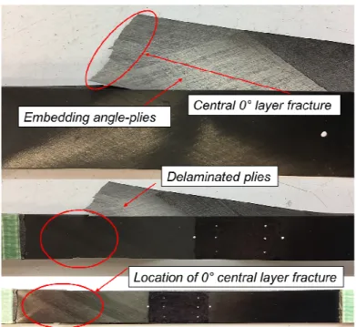
In the case of the [±206/02]s configuration, the tested specimens failed suddenly by fibre failure as shown in Figure 3. However, for the specimens with the [±286/02]s configuration, a large stress (load) drop can be observed in both the longitudinal and transverse direction curves. This drop is believed to correspond to the fracture of the central 0° layer followed instantly by delamination. This was underpinned by the post- mortem examination of the specimens where the delamination initiated at the interface between the angle-ply and unidirectional ply blocks where the first fracture of the 0°
layers occurred as illustrated in Figure 4. Furthermore, in the case of the specimens with [±286/02]s configuration where the transverse stresses are very similar, the strain measured at the load drop agreed with the failure strain of the other configuration (1.62%) that corresponds to 0° fibre fracture.
Figure 3. Typical overall stress-strain curves of the [±206/02]s laminates in (a) the longitudinal (b) transverse direction as well as the [±286/02]s laminates in (c) the longitudinal
(d) transverse direction respectively.
In both configurations, it can be seen that the overall transverse direction strain response is highly non-linear. The non-linearity is mainly associated with the angle- ply blocks surrounding the UD material: there is no in-plane shear at the laminate level, however very strong in-plane shear appears at the lamina level in the angle plies.
The high amount of transverse compression applied to the central UD layers may also play a role in the non-linear character of the transverse stress-strain curves.
A summary of the measured strains and deduced stresses including the effects of Poisson’s strain and thermal effects for both configurations can be found in Table III.
Table III. Summary of results for both angle-ply/UD configurations tested under uniaxial tensile loading.
No. of spec.
tested
Overall measured longitudinal
strain at failure/load
drop
Overall measured transverse strain at failure/load
drop
Overall stress failure/ at load drop
Mechanical transverse strain in the 0° layer
Mechanical transverse stress of 0°
layer
Transverse stress in the 0° layer
(including thermal effects)
[-] [%] [%] [MPa] [%] [MPa] [MPa]
[±206/02]s 7 1.62 -2.84 1052.6 -2.36 -143.7 -141.5
CoV [%] 3.16 7.7 3.48 9.17 9.17 N/A
[±286/02]s 6 1.62 -2.91 622.4 -2.42 -147.9 -142.4
CoV [%] 2.07 4.54 3.22 5.2 5.2 N/A
Figure 4. Illustration of the failure mechanism for the [±286/02]s
configuration: central 0° layer fibre failure immediately followed by delamination.
The mechanical transverse strain is calculated by deducting the Poisson’s strain (0.49%) from the overall measured transverse strains based on unidirectional tensile tests. The resulting mechanical strain represents the elastic strain that is induced in the 0° layers by the scissoring deformation of the angle-ply blocks. After that, it is converted to an estimated mechanical transverse stress by using the measured transverse modulus of the thin-ply material: E22 = 6.1 GPa assuming a linear elastic response.
Regarding the thermal effects, the elastic strains due to the thermal residual stresses - which are present but not measured by the video gauge – must also be included. The thermal residual stresses due to the mismatch in the coefficient of thermal expansion (CTE) of the different blocks are calculated from laminated plate theory. The residual stresses in the transverse direction are relatively small: 2.3 MPa and 5.5 MPa tension for the 20° and 28° configurations respectively. Finally, the transverse stress applied in the 0° layers is determined for each configuration by adding the thermal residual stress to the estimated mechanical transverse stresses.
As can be seen from Table III, there was a very high in-plane transverse compressive mechanical strain applied to the central UD laminate of each type: 2.36
% and 2.42 % for the 20° and 28° configurations respectively with a transverse to longitudinal strain ratio of 1.46 and 1.49. The corresponding stresses are estimated to be -143.7 MPa and -147.9 MPa respectively. The transverse strains and stresses for the two different configurations are similar as the two different ply angles are located on either side of the minimum, as illustrated on Figure 2. The overall transverse strains in the laminates of -2.84 % and -2.91 % for the 20° and 28° configurations respectively, are higher than could be achieved in a typical multi-directional laminate because they are more than double the fibre direction compressive strain to failure of the 90° plies.
The measured longitudinal failure strains are very similar (1.62%) due to the similar transverse compressive stresses. When compared to the baseline failure strain of 1.78% [4], there is only a 9% decrease in the failure strain of the UD layers despite the very high transverse compression.
CONCLUSION
A novel test configuration was presented incorporating a thin-ply composite layup that induces a multi-axial stress state of longitudinal tension and transverse compression in the central UD block of the specimen. The very high in-plane transverse compressive strain is indirectly applied to the central UD plies through the scissoring deformation of the angle-ply blocks. Two configurations were manufactured and tested with a transverse to longitudinal strain ratio of 1.46 and 1.49 applied to the central UD plies. The specimens incorporating shallower angle angle- ply blocks exhibited sudden fibre failure while the 28° configurations exhibited fibre fracture immediately followed by delamination. In spite of the very high amount of in- plane transverse compressive strain applied to the central UD fibres, the longitudinal failure strain exhibited only a 9% drop compared with that of the baseline specimens.
Furthermore, the achieved overall transverse strains are much higher than could be attained in a typical multi-directional laminate, exceeding the 90° fibre direction strain to failure, suggesting that in practice tensile failure is unlikely to be significantly affected by transverse compressive stresses.
ACKNOWLEDGEMENT
This work was partly supported by the Engineering and Physical Sciences Research Council through the EPSRC Centre for Doctoral Training in Advanced Composites for Innovation and Science (grant number EP/L016028/1). This work was also supported by the UK Engineering and Physical Sciences Research Council (EPSRC) Programme Grant EP/I02946X/1 on High Performance Ductile Composite Technology in collaboration with Imperial College London. Gergely Czél acknowledges the Hungarian National Research, Development and Innovation Office - NKFIH for funding through grants ref. OTKA K 116070 and OTKA PD 121121, the Hungarian Academy of Sciences for funding through the János Bolyai scholarship and the Hungarian Ministry of Human Capacities- EMMI for funding through the BME- Nanonotechnology FIKP grant (BME FIKP-NAT). All data required to support the conclusions are provided within the paper.
REFERENCES
[1] Wisnom, M. R. 2013. “The Challenge of Predicting Failure in Composites,” 19th Int. Conf.
Compos. Mater., pp. 12–13.
[2] Christensen, R. M. 2017. “Why progress on the failure of fiber composite materials has been so retarded,” J. Reinf. Plast. Compos., p. 073168441773355.
[3] Czél G., M. Jalalvand, and M. R. Wisnom, 2016. “Hybrid specimens eliminating stress concentrations in tensile and compressive testing of unidirectional composites,” Compos. Part A Appl. Sci. Manuf., vol. 91, pp. 436–447.
[4] Wisnom M. R., A. M. Cantera, G. Czél, and M. Jalalvand, 2017. “New Approaches to Quantifying Tensile Strength Variability and Size Effects in Unidirectional Composites,” pp.
2902–2909.
[5] Wisnom M. R., G. Czél, Y. Swolfs, M. Jalalvand, L. Gorbatikh, and I. Verpoest, 2016. “Hybrid effects in thin ply carbon/glass unidirectional laminates: Accurate experimental determination and prediction,” Compos. Part A Appl. Sci. Manuf., vol. 88, pp. 131–139.
[6] Fuller J. D. and M. R. Wisnom, 2015. “Pseudo-ductility and damage suppression in thin ply CFRP angle-ply laminates,” Compos. Part A Appl. Sci. Manuf., vol. 69, pp. 64–71.
[7] Sihn S., R. Y. Kim, K. Kawabe, and S. W. Tsai, May 2007. “Experimental studies of thin-ply laminated composites,” Compos. Sci. Technol., vol. 67, no. 6, pp. 996–1008.
[8] Lander J. K., L. F. Kawashita, G. Allegri, S. R. Hallett, and M. R. Wisnom, 2010. “a Cut Ply Specimen for the Determination of Mixed- Mode Interlaminar Fracture Toughness,” Proc. 14th Eur. Conf. Compos. Mater., no. June, pp. 1–11.
[9] Gan K. W., M. R. Wisnom, and S. R. Hallett, 2014. “Effect of high through-thickness compressive stress on fibre direction tensile strength of carbon/epoxy composite laminates,”
Compos. Sci. Technol., vol. 90, pp. 1–8.
![Figure 3. Typical overall stress-strain curves of the [±20 6 /0 2 ] s laminates in (a) the longitudinal (b) transverse direction as well as the [±28 6 /0 2 ] s laminates in (c) the longitudinal](https://thumb-eu.123doks.com/thumbv2/9dokorg/1421435.120314/6.918.173.771.172.619/figure-typical-laminates-longitudinal-transverse-direction-laminates-longitudinal.webp)