A Miocene Phreatoplinian eruption in the North-Eastern Pannonian Basin, Hungary: The Jató Member
Tamás Biró
a,⁎ , Mátyás Hencz
a, Károly Németh
b, Dávid Karátson
a, Em ő Márton
c, Alexandru Szakács
d,e, Balázs Bradák
f, Zoltán Szalai
g,h, Zoltán Pécskay
i, István János Kovács
jaEötvös University, Faculty of Science, Department of Physical Geography, Pázmány Péter sétány 1/C, H-1117 Budapest, Hungary
bMassey University, School of Agriculture and Environment, Private Bag 11 222, Palmerston North 4442, New Zealand
cMining and Geological Survey of Hungary, Paleomagnetic Laboratory, Homonna str. 9., H-1118 Budapest, Hungary
dRomanian Academy, Institute of Geodynamics, Dept. of Endogene Processes, Natural Hazard and Risk, 19-21 Jean-Louis Calderon St., R-020032, Bucharest-37, Romania
eSapientia University, Department of Environmental Sciences, Calea Turzii nr. 4., 400193 Cluj-Napoca, Romania
fBurgos University, Paleomagnetic Laboratory, Department of Physics, Av. de Cantabria, s/n, 09006 Burgos, Spain
gResearch Center for Astronomy and Earth Sciences, Geographical Institute, Budaörsi str. 45, (MTA Research Building), H-1112 Budapest, Hungary
hEötvös University, Faculty of Science, Department of Environmental and Landscape Geography, Pázmány Péter sétány 1/C, H-1117 Budapest, Hungary
iInstitute of Nuclear Research (ATOMKI), Isotope Climatology and Environmental Research Centre (ICER), K-Ar Group, Bem tér 18/c, H-4026 Debrecen, Hungary
jResearch Center for Astronomy and Earth Sciences, Lendület Pannon LitH2Oscope Research Group, Csatkai Endre u. 6-8, H-9400 Sopron, Hungary
a b s t r a c t a r t i c l e i n f o
Article history:
Received 13 November 2019 Received in revised form 10 June 2020 Accepted 10 June 2020
Available online 19 June 2020
A Middle Miocene, ~8 m thick pyroclastic succession, reported from the Bükk Foreland Volcanic Area (BFVA) in Northern Hungary (Central Europe) specified here as the Jató Member, was produced by silicic phreatomagmatism (Phreatoplinian sensulato). Two well-preserved outcrops ~8 km apart and inferred to be within ~10–50 km from source represent the discontinuously exposed, layered, paleosol-bounded, phreatomagmatic Jató Member. They show an identical phenocrystal assemblage of feldspar, biotite and amphi- bole without weathered zones or signs of erosion, that suggest deposition in one eruption phase lasting hours to months. The succession contains three subunits: 1) subunit A, 1.8 m thick, a series of well-sortedfine to coarse ash or lapilli tuff layers with constant thickness; 2) subunit B, 2.1 m thick, a series of normal-graded layers with an upperfine-grained zone containing abundant ash aggregates with a coarser-grained core and distinc- tivelyfiner-grained outer rim; 3) subunit C, 4.5 m thick, a massive, poorly to well-sorted coarse ash with gas es- cape structures and ash aggregates at its base. The upward change of these lithofacies implies an initially sustained dry fallout-dominated deposition of ash and pumice lapilli resulting in subunit A. Subsequently, mul- tiple wet and dilute Pyroclastic Density Currents (PDCs) dispersed subunits B and C. The general abundance of PDC-related ash aggregates in the middle-upper part of the succession (particularly in subunit B), and the trans- formation of a fall-dominated to a collapsing depositional regime producing wet dilute PDCs, imply the increas- ing influence of water during the eruption (Phreatoplinian sensulato). The presence of water is related to an epicontinental sea during Middle to Late Miocene in the Carpatho-Pannonian region. The transition from an ini- tial dry magmatic phase generated fallout activity followed by the emplacement of wet PDCs' rich in ash aggre- gates, when external water infiltrated from a surrounding lake or sea water entered the vent.
© 2020 The Authors. Published by Elsevier B.V. This is an open access article under the CC BY-NC-ND license (http://
creativecommons.org/licenses/by-nc-nd/4.0/).
Keywords:
Silicic hydrovolcanism Accretionary lapilli Dry-to-wet transition Miocene
Bükk Foreland Volcanic Area Carpatho-Pannonian region
1. Introduction
Phreatomagmatism occurs when hot magma of any type comes into contact with external water explosively (Morrissey et al., 2000).
Phreatomagmatism, while commonly used as synonym for hydrovolcanism, is recently more specifically referred to explosive volcanism resulting from molten-coolant interaction (MFCI) processes typically in subaerial conditions (Németh and Kósik, 2020). There are
well-documented Late Quaternary pyroclastic formations that show signs of interaction between silicic magma and a significant body of ex- ternal water: the Hatepe and Rotongaio ashes of the AD 183 Taupo Eruption in New Zealand (Walker, 1981a), the 25.4 ka Oruanui Forma- tion of the Taupo Volcano (Self and Sparks, 1978;Self, 1983;Wilson, 2001), the ~70 ka Neapolitan Yellow Tuff from the Campi Flegrei caldera in Italy (Cole and Scarpati, 1993), the 161 ka Kos Plateau Tuff from the Eastern Aegean (Allen and Cas, 1998), and the Askja AD 1875 layer C (Sparks et al., 1981). The expression“phreatoplinian”, based on fallout tephra dispersal and grade of fragmentation, was applied to silicic erup- tions that result in pyroclast deposition to the same or even larger areal
⁎ Corresponding author.
E-mail address:birotamas@caesar.elte.hu(T. Biró).
https://doi.org/10.1016/j.jvolgeores.2020.106973
0377-0273/© 2020 The Authors. Published by Elsevier B.V. This is an open access article under the CC BY-NC-ND license (http://creativecommons.org/licenses/by-nc-nd/4.0/).
Contents lists available atScienceDirect
Journal of Volcanology and Geothermal Research
j o u r n a l h o m e p a g e :w w w . e l s e v i e r . c o m / l o c a t e / j v o l g e o r e s
extent than Plinian ones (N500 km2), showing a high degree of frag- mentation reaching a scaled value of over 70% (Self and Sparks, 1978;
Houghton et al., 2015a). Phreatoplinian tephras show less characteristic change of granulometric parameters with distance from vent than Plinian ones (Walker, 1981a) and their total grain-size distribution show poor sorting due to common ash accretion and contemporaneous fallout with larger pumice clasts (Walker, 1981a;Sparks et al., 1981).
In practice, total grain-size distribution, change in granulometric pa- rameters with distance from vent, and D-F (dispersal versus fragmenta- tion) values for ancient, poorly exposed pyroclastic layers are not easy to determine due to the common scarcity of suitable outcrops and the difficulty of identifying and correlating single fallout layers that can be linked to the same explosive event. The phreatomagmatic origin of an- cient tephra could be deduced from 1) the textural features of pyroclasts that can be associated to the presence of water at the vent causing quench fragmentation, and 2) the identification of sedimentological fea- tures caused by water vapour in the eruption column and/or water in the deposited tephra. In this way, a typical phreatomagmatic tephra can be distinguished on the basis of i) the significant amount offine ash (sensulato) (McPhie, 1986); ii) the abundance of ash aggregates and fine ash coating on larger pyroclasts (coarse ash to lapilli) (Wilson, 2001; Ellis and Branney, 2010); iii) the associated fine- grained, non-welded pyroclastic density current (PDC) deposits which commonly contain plant remains (Porreca et al., 2008); iv) the charac- teristically angular and blocky ash particles (Scarpati et al., 1993;Ellis and Branney, 2010) showing solidity and convexity values dominantly between 0.8 and 1.0 (Liu et al., 2015); and v) the presence of diatoms, incorporated from external water, that came into contact with hot sili- cate melt (Van Eaton et al., 2013). For example, the phreatomagmatic origin of the Late Carboniferous Cana Creek Tuff (Australia;McPhie, 1986), the Ordovician Whorneyside Tuff (English Lake District;
Branney, 1991) and the Miocene Deadeye Member (Snake River Plain, USA;Ellis and Branney, 2010) were determined by recognizing some of the features listed above. However, during several silicic eruptions, external surface water came into contact with the magma after partial or complete volatile exsolution; e.g. after initial magmatic fragmenta- tion (Self, 1983;Houghton et al., 2015a, 2015b;White and Valentine, 2016) and only ~30% of the resulting glass fragments in the ash fraction show particle shape signatures related to water-induced quench frag- mentation (e.g. MFCI;Büttner et al., 2002). Consequently, determining the phreatomagmatic origin (sensu stricto) for ancient silicic succes- sions is a real challenge. Revealing water influence on a silicic eruption in the geological past thus requires careful investigation of the entire succession recording continuous presence of water in the eruption col- umn and the aggrading pyroclastic layers. We use the term Phreatoplinian sensu lato (with capital‘p’) to describe deposits with ev- idence for large-scale interaction of magma and external water, but lacking sufficientfield exposure or data to plot on a Walker dispersal- fragmentation classification diagram (Walker, 1973).
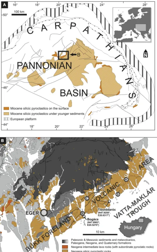
During the Early and Middle Miocene (Szabó et al., 1992;Pécskay et al., 1995, 2006) widespread silicic explosive volcanism took place in the intrabasinal part of the Carpatho-Pannonian region (CPR;
Fig. 1a) in present-day Eastern-Central Europe in several episodes (Szabó et al., 1992;Pécskay et al., 2006). Related pyroclastic rocks cover at least 50,000 km2 based on qualitative areal estimates (Pantó, 1965;Ravasz, 1987). The average cumulative thickness of the Early to Middle Miocene silicic pyroclastic rocks was estimated at ~90 m by considering several thousand boreholes, suggesting a ca. 4500 km3total bulk volume estimate (Lukács et al., 2018). The long timespan and the large volume are comparable with pyroclastic rocks from ignimbriteflare-up episodes caused by high mantleflux (0–10 Ma; 103–104km3;Gravley et al., 2016and references therein).
The largest exposed occurrence of the silicic pyroclastic rocks in the CPR is the Bükk Foreland Volcanic Area (BFVA). Here, on an area of ca. 8 × 40 km, a ~ 200 m thick pyroclastic succession crops out (Szakács et al., 1998).
In this paper, we present a detailed physical volcanological descrip- tion of a bedded,fine-grained unit with abundant ash aggregates from the BFVA, specified as the Jató Member, that was deposited ~14.9 Ma ago according to zircon U\\Pb dating (Lukács et al., 2015, 2018), in a subaerial setting. The general abundance of PDC-related ash aggregates in the middle to upper part of the succession, and the transformation of a fall-dominated to a collapsing depositional regime producing wet ig- nimbrites imply abruptly intervening water influence on a silicic erup- tion (Phreatoplinian sensulato).
2. Geological background
Eastward drift and counterclockwise rotation of two microplates (Alcapa and Tisza-Dácia) into the“Carpathian embayment”of the CPR during Late Oligocene to Early-Middle Miocene times induced large- scale normal faulting and crustal thinning related to strong extension (Csontos et al., 1992;Márton and Fodor, 1995, 2003; Márton and Márton, 1996;Márton et al., 2007). The extension induced decompres- sion melting in the asthenosphere and the lithospheric mantle, which was previously enriched by subduction-related metasomatism (Szabó et al., 1992;Koněcný et al., 2002;Seghedi et al., 2004;Harangi and Lenkey, 2007;Kovács and Szabó, 2008). Magmatism at the surface re- sulted in generation of volcanic edifices such as intermediate (mostly andesitic) groups of lava domes and composite volcanoes (e.g.: Central Slovakian Volcanic Field, Visegrád Mountains, Börzsöny Mountains;
Koněcný et al., 1995,Karátson et al., 2000, 2007), and silicic explosive volcanism-related ignimbritefields in the intrabasinal part of the CPR (Fig. 1a) during the Early and Middle Miocene, i.e. from ~21 Ma to ~12 Ma on the basis of extensive K\\Ar dating (Pécskay et al., 1995, 2006).
The Early and Middle Miocene silicic pyroclastic successions, up to few hundreds of metres thick, were penetrated by boreholes in South- ern Transdanubia, the Great Hungarian Plain, the Transcarpathian Basin and the Transylvanian Basin under a pile of Neogene to Quater- nary siliciclastic deposits which may reach up to 4000 m in thickness (Széky-Fux et al., 1987;Zelenka et al., 2004) including salt in the Tran- sylvanian Basin (Szakács et al., 2012). Scattered surface occurrences are also known in several areas, including the Börzsöny and Cserhát Mountains, the southern and northern foreland of the Mátra and Bükk Mountains, the Eperjes-Tokaj Mountains, the Mecsek and the Transyl- vanian Basin (Fig. 1a;Pantó, 1962;Hámor et al., 1979;Szabó et al., 1992;Zelenka et al., 2004;Szakács et al., 2012). The largest and most complex surface representation of these pyroclastic rocks is found in the Bükk Foreland Volcanic Area (BFVA;Fig. 1b) covering an area of at least 320 km2. The oldest dated ignimbrite in the BFVA gave a 20.40 ± 1.72 Ma biotite K/Ar age (Márton and Pécskay, 1998). The Harsány Ig- nimbrite, which is found at the top of the BFVA sequence and consid- ered the youngest pyroclastic succession byLukács et al. (2015), yielded an age of 15.66 ± 0.66 Ma by whole rock K/Ar dating (Márton and Pécskay, 1998) and 13.35 ± 1.01 Ma by biotite K/Ar dating (Lukács et al., 2007), while U/Pb dating on zircons yielded 14.358 ± 0.015 Ma. New zircon U/Pb ages from the entire succession of BFVA sug- gests an age range of the volcanism from ~18.2 to 14.4 Ma (Lukács et al., 2018).
The pyroclastic rocks cropping out in the BFVA are dominantly composed of thick ignimbrites with non-welded, slightly- to densely- welded facies interbedded, and/or capped by thin pyroclastic fall de- posits commonly associated with locally thick, valley-confined reworked tephras between the major ignimbrite units (Fig. 2;
Capaccioni et al., 1995;Szakács et al., 1998). Thefive known voluminous ignimbrite units of BFVA (at least 20 m thick each) are, in chronological order, the Eger Ignimbrite, Mangó Ignimbrite, Bogács Ignimbrite, Demjén Ignimbrite and Harsány Ignimbrite (Lukács et al., 2018and ref- erences therein). Paleomagnetic declination results, radiometric ages, lithological features and phenocryst assemblages of these major ignim- brites are summarized inFig. 2.
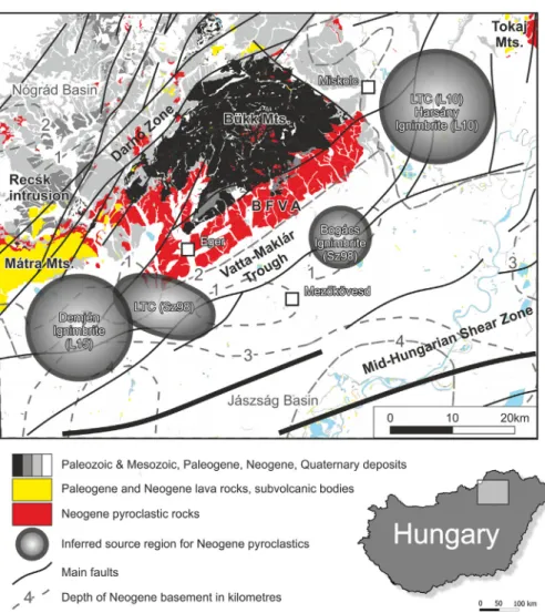
The location of source vents for various BFVA pyroclastic successions is unknown. However, qualitative or semiquantitative interpretations based on various investigations implied multiple source areas, that are located in the Vatta-Maklár Trough at the southern margin of the Bükk Mountains (Fig. 1b): Directional magnetic fabric of the Bogács ig- nimbrite indicated a source region south of Tibolddaróc (Szakács et al., 1998). Pyroclast transport direction indicators and the direction of
grain-size coarsening from the Lower Tuff Complex point towards the southwest from Eger (Fig. 1b;Szakács et al., 1998). The eastward thick- ening of the Lower Tuff Complex ignimbrites and the Harsány Ignim- brite obtained from borehole data shows an eastern source region (Lukács et al., 2010). Lateral facies variations in the Demjén Ignimbrite are consistent with a source region close to the southwestern margin of the BFVA (Lukács et al., 2015).
Fig. 1.Regional geological setting (a) and volcanological map (b) of the Bükk Foreland Volcanic Area with the studied Bogács and Tibolddaróc sites marked. a) Areal distribution of Miocene silicic pyroclastics in the Carpathian-Pannonian Region. The black rectangle with“B”marks the location of the Bükk Foreland Volcanic Area. The map was modified afterSzakács et al.
(2018). b) Volcanological map of the Bükk Foreland Volcanic Area. Basemap: 1:100.000 geological map of Hungary, published by the Mining and Geological Survey of Hungary (https://map.mbfsz.gov.hu/fdt100/). Exact location of the Bogács and Tibolddaróc sampling sites is specified with WGS84 geographic coordinates. Sampling sites ofSzakács et al.
(1998): B–Bogács-Abandoned quarry; C–Cserépfalu; S–Sály; K–Kisgyőr-Kőbánya-tető.
This study focuses on a complex, bedded pyroclastic succession de- scribed as the Tibolddaróc Succession (Lukács et al., 2007, 2015), found between the Bogács and Harsány Ignimbrites (Fig. 2).Szakács et al. (1998)documented the basic physical volcanological features of the Tibolddaróc Succession usingfield volcanology data from exposures at the settlements of Bogács, Cserépfalu, Tibolddaróc, Sály and Kisgyőr- Kőbányatető(Fig. 1b) and argued the succession is a phreatomagmatic pyroclastic complex with abundant ash aggregates. Later, a more de- tailed field observation on the succession at the settlement of Tibolddaróc (Fig. 1b) allowed distinguishing 11 units (layer B-L;
Lukács et al., 2007): four pyroclastic fall deposits with 0.2–0.5 m thick- ness, from which Td-L is produced by phreatomagmatic fallout, three ig- nimbrites with 15, 1 and 0.5 m thicknesses, and four reworked volcaniclastic layers, respectively. Zircon U/Pb ages of Td-L (16.7 ± 0.25 Ma), Td-J (16.2 ± 0.30 Ma), Td-H (14.88 ± 0.20 Ma), and Td-E, F (14.65 ± 0.20 Ma) from Tibolddaróc imply quiescence periods as long as 0.3–1.2 Ma between the dated units (Lukács et al., 2015), character- ized by the formation of epiclastic deposits.
In this study a detailed description on the best-preserved part of the Tibolddaróc Succession is given, which is shown to be produced by si- licic phreatomagmatism and designated here as the Jató Member. The term“Jató”is borrowed from Jató Hill near Bogács village, because the best-preserved occurrence of the studied unit crops out on the eastern flank of that hill.
3. Materials and methods 3.1. Field description
Basic physical volcanological features of each individual pyroclastic bed, such as thickness, bedform, sorting, grain-size characteristics,
colour and contact details were recorded on thefield in the vicinity of the two localities (Figs. 3, 4). The best exposures are known near the vil- lage of Bogács and Tibolddaróc (Fig. 1b). Detailed description was only possible for a particular ~8.5 m part of the succession (mentioned above; for details seeSection 4.2), because other units are heavily weathered.
3.2. Granulometry
To understand the grain-size distribution, indicative of transport mode of the pyroclasts in each subunit of the Jató Member, 33 samples were analysed (Fig. 5). Standard granulometric methodology was ap- plied: dry sieving and laser diffraction particle sizing in order to com- pute median grain size and sorting coefficient ofInman (1952)and F2 parameter ofWalker (1983). Detailed description of granulometric analyses is provided in the Appendix. Granulometry also helped to seg- regate individual pyroclasts for further textural and chemical investiga- tions. Eleven samples from subunit A, seven from subunit B and four from subunit C were investigated from Bogács. In addition, eight sam- ples from subunit A, one from subunit B and two from subunit C were investigated from Tibolddaróc. Thus, comparison between the same layers from Bogács and Tibolddaróc was possible across eight well- defined layers. Granulometric analyses were performed only on those layers which are friable or poorly cemented.
3.3. Anisotropy of magnetic susceptibility
Magnetic susceptibility is the induced magnetic moment of a sub- stance if an outer magneticfield is applied. Anisotropy of magnetic sus- ceptibility (AMS) measures the orientation of magnetic carriers in a rock. AMS therefore is a widely used technique to investigate the Fig. 2.Lithological, stratigraphic, petrographic, geochronological and paleomagnetic features of the main pyroclastic complexes in the BFVA. Unit thicknesses are not to scale. The investigated Tibolddaróc Succession was deposited between the Bogács and Harsány Ignimbrite units and marked with a black rectangle. Sz '98–Szakács et al. (1998), L '18–Lukács et al. (2018). Types of radiometric age determinations: b–K/Ar age of biotite; wr–K/Ar age of whole rock; z–zircon U/Pb ages. Source of data: a–Capaccioni et al. (1995); b– Szakács et al. (1998); c–Lukács et al. (2007); d–Czuppon et al. (2012); e–Póka et al. (1998); f–Márton and Pécskay (1998); g–Lukács et al. (2015); h–Lukács et al. (2018). Opx– orthopyroxene; Amp–amphibole; Bio–biotite; Plg–plagioclase; San–sanidine; Qtz–quartz.
magnetic fabric of various rocks (Rochette et al., 1992). AMS can be de- scribed as a triaxial ellipsoid with Kmaxbeing the maximum, Kintthe in- termediate and Kminthe minimum susceptibilities. AMS is routinely used for pyroclastic density current deposits to determineflow direc- tions and depositional processes (Cañón-Tapia and Mendoza-Borunda, 2014;Ort et al., 2015). In this study, AMS is used to obtain information on the amount of shearing during pyroclast deposition, then to decide whether a layer is emplaced by pyroclast fallout or by pyroclastic den- sity current. Forty-eight standard cylindrical samples were drilled in thefield for AMS measurements at Bogács from the following layers:
layer 13 of subunit A, layer 2 and 4 from subunit B, and three samples from the base and top of subunit C. Samples were recovered from two
sites from subunit C: from ~1 m above its base, and from below the weathered zone at the top of this subunit (Fig. 5). Details of the AMS measurements and corresponding statistical treatment are presented in the Appendix.
4. Results
4.1. Units of the Tibolddaróc Succession
In this study, the stratigraphy and physical volcanological features of the layered Tibolddaróc Succession, which was deposited in between the Bogács and Harsány Ignimbrite units, were examined at the village Fig. 3.Lithological features of the pyroclastic succession at Bogács and Tibolddaróc. The succession contains four units (I-IV) at Bogács and three units (I-III) at Tibolddaróc. Unit IV is absent at Tibolddaróc. Only the uppermost part of unit I is cropping out at Bogács. The two occurrences of the Jató Member and Unit III can be readily correlated. Only the Jató Member is not effected by heavy weathering. The thickness of the Harsány Ignimbrite unit is not to scale at Tibolddaróc.
of Bogács and Tibolddaróc (Fig. 1b) located 8.6 km apart. Other occur- rences of the Tibolddaróc Succession at Bogács–an abandoned quarry, Sály, Kisgyőr–Kőbányatető(Fig. 1b) mentioned bySzakács et al. (1998) are heavily weathered; individual beds cannot be confidently
distinguished; hence we have not found them suitable for detailed macro- and microtextural analysis. The succession has slightly different overall thickness at the two localities, ~14.5 m at Bogács and ~13 m at Tibolddaróc, respectively. As a result offield mapping and vertical Fig. 4.Field appearance of Unit I, III and IV. A–The boundary between the Bogács ignimbrite and subunit A of Unit I at Tibolddaróc. Arrow points to an ash aggregate; B–Ash aggregates in subunit B of Unit I at Tibolddaróc; C–Unit I at Tibolddaróc, note the location of ash aggregate rich zone on picture B; D–Unit III at Tibolddaróc; E–Unit III at Bogács; F–Unit IV and the Harsány ignimbrite at Bogács.
sectioning, four lithostratigraphic units have been distinguished from base to top labelled as unit I, unit II (i.e. the Jató Member), unit III and unit IV, respectively, based on bedding characteristics, average grain- size and colour (Figs. 3, 4, 5). The boundaries between the units are lat- erally continuous, clearly visible and sharp. Unit IV is only exposed at Bogács and it is unclear that at Tibolddaróc it has ever existed and/or it has been eroded. The lower and upper parts of the succession (units I, III and IV) are weathered, thus their original bedding and
granulometry could not be determined in thefield. Sedimentological features of the identified units are summarized inTable 1.
4.2. Field and grain-size characteristics of the Jató Member (unit II) As summarized inTable 1, the Jató Member has been subdivided into three subunits (subunit A, B and C;Figs. 3, 5). In more detail, four lithofacies (LF1–4 hereafter) can be discriminated based on thickness, Fig. 5.Detailed stratigraphic log, granulometry and magnetic fabric of the Jató Member. Mdϕandσϕare the median grain size and theInman (1952)sorting parameter, respectively inϕ units (ϕ=−log2d, where d is the grain diameter in mm). F2 is the amount of theb1/16 mm (b0.063 mm) fraction, expressed in weight percent (Walker, 1983). Symbols: circles–samples from Bogács; squares–samples from Tibolddaróc. Black symbols mark the positions of samples collected for AMS measurements. Stereoplots: square–Kmax, triangle–Kint, circle–Kmin, open symbols mark samples, where the F-test was negative. See the Appendix for further details. LF is lithofacies; see chapter 4 andTable 2for further discussion.
grain-size characteristics and abundance of ash aggregates (Table 2).
The full granulometrical dataset is available in the Electronic Supple- mentary Material. There is a successive change of dominant LF: Subunit A consists of 15 layers, from which layer 1, 3, 4, 6, 8, 10, 11, 12, 14 representing LF1 (Table 2). It is a well-sorted tuff or lapilli tuff with typ- ical Mdφbetween 0 and 1 (0.5–1.0 mm) and variable sorting (σφis be- tween 1 and 2.5). The grain-size distribution curve of LF1 is characterized by a normal peak centered around 0.5 mm (φ= 1). Con- stant thickness of LF1 layers are observed in the several m2to several 10 m2-sized, scattered outcrops Six layers, namely layer 2, 5, 7, 9, 13, 15 occur in subunit A representing LF2 (Fig. 6), which is a moderately sortedfine tuff often containing pumice lapilli characterized by Mdφbe- tween 2 and 3 (0.25–0.125 mm), andσφof 2–3. A smaller symmetric peak in the grain-size distribution is present atφ= 6 (0.016 mm) be- sides the main peak atφ= 2 (0.25 mm). The thickness of LF2 varies from layer to layer between 1 and 20 cm. LF1 and 2 layers are distrib- uted nearly homogeneously in subunit A, i.e. there is no part of subunit A, where LF2 layers are more frequent.
The layers of subunit B have a uniform, characteristic appearance:
each consists of a coarser-grained lower part with median grain size be- tween 0.5 and 1 mm (Mdφ: 0.3–0.5) and moderate sorting (σφ: 1.61 and 1.93) overlain by afine-grained upper part with median grain size between 0.5 and 0.1 mm (Mdφ: 1–3.7) and poor sorting (σφ~3), con- taining very abundant ash aggregates (Table 2). These layers are desig- nated as LF3 in our interpretative schema (Fig. 7a, b). Except for the lowermost layer in subunit B, all layers defined as LF3 contain ash aggre- gates in the upper, relativelyfine-grained part. In this paper‘ash aggre- gate’describes all types of ash aggregates, regardless their internal structure. Most ash aggregates in LF3 show a relatively coarse-grained core and afine-grained rim defining a layered structure. The grain- size distribution of cores and rims of ash aggregates was not measured in this study. However, contrasting grain-size of the coarser cores and relativelyfine-grained rims is evident to the naked eye (Fig. 7c, d, e).
The abundance and size of ash aggregates show a general gradational pattern in LF3. Just above the lower, coarser part, sparse, usually 4–10 mm-sized ash aggregates are typical. In this zone, ash aggregates show weak clustering rather than homogeneous distribution. Towards the top of the layer, the size of ash aggregates decreases (down to 1–2 mm in diameter); on the contrary, their abundance increases (Fig. 7c).
The 3–10 cm thick uppermost zone of the layers is composed entirely of ~2 mm-sized ash aggregates. Most of the ash aggregates show spher- ical geometry. Rarely, especially theN0.5 cm-sized ash aggregates are deformed, showing an ellipsoid-like contour in cross section (Fig. 7e).
Rarely, the core of ash aggregates is occupied by a 2–3 mm large feldspar phenocryst or lithic clast. In layer 7 some ash aggregates with 1–1.5 cm diameter show a more complex internal structure than the typical coarse core-fine rim type observed in LF3. Such ash aggregates show variation of relativelyfine-grained and coarser-grained concentric layers. This is the only layer where this type was observed.
Above subunit B, a diffusely-bedded, 4.5 m thick tuff with abundant gas escape structures is noted, designated as subunit C and LF4 (Table 2, Fig. 8). Subunit C shows slight upward coarsening of median grain size at Bogács: 0.1 mm (Mdφ= 3.5) at its base, 0.13 mm (Mdφ= 3) at 1 m above its base, 0.3 mm (Mdφ= 1.7) in the middle part and 0.45 mm (Mdφ= 1.2) below the weathered zone. The deposit sorting, expressed inσφis between 1.7 and 2.4. Two peaks at 0.015 mm (φ= 6), and 0.5 mm (φ= 1), result in a bimodal grain-size distribution.
Layer 3, 6, 8, 10, 12, 13, 14 from subunit A, layer 1 from subunit B, and subunit C were sampled for granulometrical analyses both at Bogács and at Tibolddaróc. Most of these layers show almost identical granulometry features (Fig. 5, Electronic Supplementary Material). Dif- ferentσϕvalues characterize only the lower part of layer 1 in subunit B at the two outcrops, namely, σϕ is 1.61 at Bogács and 2.56 at Tibolddaróc, but Mdϕvalues are similar, 0.26 and 0.70, respectively.
By contrast, both the Mdϕandσϕvalues are different (1.2 and 4.0, and 2.2 and 2.6, resp.) below the weathered top of subunit C in the
Table 1
Characteristics of the Tibolddaróc Succession.
Unit Description Interpretation
IV Thickness: shows laterally changes in the outcrop; maximum: 0.5 m.
Structure: well-sorted coarse tuff and lapilli tuff layers with laterally variable thickness.
Average diameter of pumice clasts: 0.5 cm and never exceeds 1 cm.
Fall deposits
III Thickness: ~4 m at Bogács and ~ 5 m at Tibolddaróc. Its overall thickness can only be determined with uncertainty, because the outcrops are not continuous laterally.
Structure: two subunits (subunit A and B).
The internal structure and grain-size characteristics of unit III are different at Bogács and Tibolddaróc.
Subunit A: the lowermost 26 cm thick layer of subunit A at Tibolddaróc is a veryfine yellowish white tuff with faint bedding.
Above this layer the remaining 94 cm part of subunit A is a series of coarse well-sorted tuff layers 3–20 cm thick each containing cm-sized dense pumice clasts, grey, banded lithic clasts and mm-sized quartz, feldspar and biotite crystals. Maximum diameter of pumice clasts: 5 cm (average of the three biggest pumice clast). Lithics are much rarer than pumice clasts and have a maximum diameter of 1.5 cm. Quartz, feldspar and biotite crystal fragments with 3 mm diameter are presented.
At Bogács, the lowermostfine tuff is ~15 cm thick. Similarly, the coarser-grained upper part is just ~50 cm thick here, and finer-grained than at Tibolddaróc.
Subunit B: gradational lower contact; only the lowermost 1.5 m thick part of this subunit can be investigated. The upper ~3 m thick part of Subunit B has a lower porosity and much higher clay content than its lower part, suggesting weathering. The lowermost layer of subunit B is a ~ 40 cm thick,fine grained, poorly sorted tuff with rare ~1 cm-sized pumice clasts at both occurrences.
Above that layer, a ~ 0.5 m thick poorly sorted layer with abundant cm-sized pumices developed. The maximum size of pumice clasts is 3 cm at Bogács and 6 cm at Tibolddaróc. After that, afine-grained, poorly sorted layer was deposited, which becomes denser and clay-rich gradually upwards.
Subunit A: fall deposits Subunit B: PDC deposits +/−fall deposits
Jató Member (II)
Thicknessis different at the two localities: ~8 m at Bogács and 7 m at Tibolddaróc.
Structure: three subunits (subunit A, B and C).
Subunit A: 1.8 m thick at both localities. It mainly consists of the alternation of coarse tuff layers, 2–20 cm thick and lapilli tuff layers, up to 40 cm thick, with laterally constant thickness at outcrop scale. The sorting of individual layers are good.
Subunit B: 2.1 m thick at both sites, consists of layers with a uniform internal structure.
The basal part is a coarse-grained tuff, whereas the upper part isfine-grained and contains abundant ash aggregates.
Subunit C: 4.5 m thick at Bogács and 3 m thick at Tibolddaróc, is a massive lapilli tuff with 2 cm maximum pumice diameter.
Minor grain-size variations indicate only diffuse bedding in the subunit. At the lowermost 1 m thick part it contains abundant ash aggregates and gas escape structures.
The uppermost 2 m thick part is heavily weathered, it is clay-rich, and much less porous than the lower parts. The colour of
Subunit A: fall deposits Subunit B: wet PDC deposits Subunit C: wet ignimbrite
two outcrops (Figs. 3, 5; note the different thickness of subunit C at Bogács and Tibolddaróc).
4.3. Anisotropy of magnetic susceptibility
The mean magnetic susceptibilities of the investigated samples from the Jató Member are weak, ranging between 35 and 100 × 10−6SI (Fig. 9a). Most of the samples haveb70 × 10−6SI mean magnetic sus- ceptibility. Samples from the lower part of subunit C have slightly higher magnetic susceptibilities (80–100 × 10−6SI) considering the studied samples. The P′of the investigated samples are also weak (generally lower than 0.5%). Only three samples show P′values higher than 1%. It is important however, that P′is independent of the mean magnetic sus- ceptibility (Km;Fig. 9a). All layers show significant scatter of the ellip- soid shape parameter (−1bTb0.8;Fig. 9b). The F-test value of 24 out of the 53 investigated sample isb3.4817, which implies statistically isotropic magnetic fabric for 45% of the samples.
The distribution anisotropy of principal susceptibilities is generally poor (Fig. 5, 9b). The orientation of the principal susceptibility axes is generally chaotic, except in layer 13 of subunit A and in layer 2 of sub- unit B. In the former, all three axes are grouped (Fig. 5), and Kminaxes are vertical, Kmaxaxes are W-E oriented and consequently the Kint axes are oriented in N-S direction. In layer 2 of subunit B, Kmax axes are also aligned in the W-E direction, but the other two axes are intermixed.
5. Discussion
5.1. Deposition from multiple eruption phases at subaerial setting recorded in the Tibolddaróc Succession
Four main units are identified within the Tibolddaróc Succession.
Detailedfield logging of the two occurrences at Bogács and Tibolddaróc has shown that the two outcrops, located 8.6 km apart, consist of the same pyroclastic units. Consequently, the existence of the same,
dominantlyfine-grained pyroclastic units at both sites imply explosive eruptions that caused tephra deposition over an area of at least 102– 103km2.
Weathered zones occur at the top of unit I, III and the Jató Member which display a transitional lower contact, indicating that the fresh tephra of each unit incrementally weathered towards the top of the units (Figs. 3, 6c,8c). The upper contacts of the weathered zones are sharp and irregular. The presence of weathered zones at the upper part of the eruptive units is a common feature of pyroclastic successions aggraded during discrete volcanic phases separated by long quiescence periods (on the order of 102–105years) associated with intense surface weathering and soil formation (e.g. Santorini:Vespa et al., 2006; Taupo Volcanic Zone:Wilson, 1993; Vesuvius:Vogel et al., 2016). A lowermost fine accretionary lapilli-bearing tuff (Td-L), afine tuff (Td-J), a lapilli- bearing poorly-sorted tuff (Td-H), and a bedded sequence consisting of fine to coarse tuff layers (Td-E, F) separated by reworked volcaniclastic layers were described at Tibolddaróc (Lukács et al., 2007, 2015). However, both the lithostratigraphy and the genetic inter- pretation ofLukács et al. (2015)differ from what is suggested in this work. Nevertheless, Td-L (inLukács et al., 2015) can be tentatively iden- tified as subunit A of unit I in our division; Td-J and the overlying volcaniclastics to subunit B of unit I in our division; Td-H and the volcaniclastics on its top to the Jató Member; and Td-E, F and overlying volcaniclastics to unit III. Zircon U/Pb ages of Td-L (16.7 ± 0.30 Ma), Td-J (16.2 ± 0.30 Ma), Td-H (14.88 ± 0.014 Ma), and Td-E, F (14.7 ± 0.20 Ma;Lukács et al., 2015) from Tibolddaróc imply quiescence periods as long as 0.3–1.2 Ma between the dated units. The inferred long periods of volcanic quiescence between the emplacement of the units and the warm and humid climate reconstructed for the Middle Miocene (Jiménez-Moreno et al., 2005) suggest intense paleosol formation in the volcanic quiescence periods. Reconstructed average annual paleo temperature was 18–20 °C and the average annual paleo precipitation was 1400–1200 mm for the Badenian stage (corresponding to Langhian and most of Serravallian in standard chronostratigraphy), based on the palynological analysis of Tengelic 2 borehole (Jiménez-Moreno et al., 2005) located in Southern Transdanubia, 200 km away from Bogács to the southwest. Consequently, the presence of 2–3 m thick paleosols at the top of separate pyroclastic successions indicate, that at Bogács and Tibolddaróc localities there was a subaerial environment in the Middle Miocene, where pyroclast deposition occurred during multiple eruption phases. In the Middle Miocene, an incremental transgression from SE to- wards NE from 16.3 to 13.4 Ma was reconstructed (Kovács et al., 2007), which resulted in an archipelago with large areas covered by shallow sea and 102–103km2large land patches (Kovács et al., 2007;Kováč et al., 2017). The Bükk Mts. and their vicinity might have been subaerial terrains (Bérczi et al., 1988;Szakács et al., 1998;Kováčet al., 2017) ac- cording to the presence of sediments from terrestrial environments.
The presence of paleosols in the Tibolddaróc Succession confirms these former paleoenvironmental reconstructions.
The heavy weathering of unit I and III hinders their genetic interpre- tation. To interpret lithofacies and draw an eruption scenario is only possible for the Jató Member, the subject of this study, which shows the characteristics of an explosive eruption influenced by external water.
5.2. The Jató Member
5.2.1. Fingerprints of phreatomagmatism in ancient pyroclastic successions Determination of the main type of a volcanic eruption from a pyro- clastic deposit can be based on thickness and grain-size data collected in a number of spatially distributed outcrops. In optimal circumstances, the total grain-size distribution can be calculated (Walker, 1981a) and the data can be plotted on the dispersal (D) versus fragmentation (F) diagram by interpolating isopach lines (Walker, 1973). The area cov- ered by a typical phreatoplinian fall deposit overlaps with the area cov- ered by plinian fall deposits generated from“dry”, magmatic eruptions;
Table 1(continued)
Unit Description Interpretation
the weathered part gradually transforms upwards from light grey into dark grey. All the layers contain abundant feldspar, biotite, amphibole and sparse quartz phenocrysts.
I Thickness: ~3 m at Tibolddaróc. Only the uppermost 0.5 m is exposed at Bogács.
Structure: ~0.5 m thick basal subunit (subunit A), which directly overlies the Bogács Ignimbrite, and a ~2.5 m thick upper subunit (subunit B;Fig. 3).
Subunit A: well-sorted, veryfine-grained light greyfine tuff, 0.5 m thick and containing abundant cm-sized ash aggregates. Its thickness is constant laterally.
The largest ash aggregate reaches 3 cm in diameter.
Subunit B: 2.5 m thick, poorly-sorted, yellowish grey, heavily altered tuff. Two types of layers:
i) dark-grey,fine grained, hardly compacted tuff with abundant deformed,flattened ash aggregates; the thickness of these layers is changing laterally between 3 and 15 cm in places showing faint cross-bedding features;
ii) light brown poorly-sorted ~60–70 cm thick layers with mm-sized pumice clasts;
ash aggregates within the tuff are up to 1 cm in diameter and oftenflattened.
The uppermost ~1 m thick part of unit I is heavily weathered.
Subunit A:
phreatomagmatic fall deposit
Subunit B: wet PDC deposits
however, the degree of fragmentation of typical phreatomagmatic tephras is much higher than those found in dry magmatic ones (Self and Sparks, 1978;Cioni et al., 2015;Houghton et al., 2015a). The original spatial extent and total grain-size distribution of ancient successions displaying poor preservation are typically unknown. As a consequence, demonstration of the involvement of external water in ancient volcanic eruptions is usually challenging, and must be based either on the
recognized characteristics of pyroclast textures, or on sedimentological features of the pyroclastic beds which can record (i) water influence on fragmentation at vent, (ii) presence of water in the eruption column, and also (iii) in the deposited tephra (Houghton et al., 2015b).
Once the following criteria (a-e) are determined, they can be used as proxies to identify the phreatomagmatic origin even for poorly exposed, ancient pyroclastic successions (cf.Houghton et al., 2015b): a) the Table 2
Features of various lithofacies in the Jató Member.
Lithofacies Description Layers Representative grain-size distribution curve Interpretation
LF1 Thickness: 4–35 cm.
Lithology: well-sorted coarse tuff, rich in pumice clasts (N80 wt% in general), showing sharp but non-erosive contacts; thickness is laterally constant at an outcrop scale; components: pumice clasts, biotite, feldspar and subordinate amount of amphibole and small lithics (b5%).
Granulometry: Mdϕ: generallyb1 (on average, 0.5 mm); sorting: variable, ranging between 1 and 2.5; F2: generallyb10 wt%.
Grain-size distribution: dominated by a normal peak atϕ= 1 (0.5 mm).
The grain-size distribution of layer 14, a ~35 cm thick coarse tuff, shows a second but very moderate peak offine ash at 6ϕ(0.016 mm).
Layer 1, 3, 4, 6, 8, 10, 11, 12, 14 in subunit A
Fall deposit
LF2 Thickness: 1–20 cm.
Lithology:fine tuff with sharp but non-erosive or, sometimes, diffuse lower contact; components:fine glass shards, pumice fragments and phenocrysts (N80), larger, 1–3 mm-sized pumice clasts, lithics and biotite fragments are rare (b20 wt%).
Granulometry: Mdϕandσϕ: between 2 and 3; F2: 30 wt%;
Grain-size distribution: a smaller symmetric peak in the grain-size distribution is present atϕ= 6 (0.016 mm) besides the main peak atϕ= 2 (0.25 mm).
Layer 2, 5, 7, 9, 13, 15 in subunit A
PDC deposit from low-energy, dilute currents
LF3 Thickness: 5–40 cm.
Lithology: normal graded coarse to veryfine tuff, consisting of a relatively coarser basal part and afine-grained upper part often bearing abundant ash aggregates (‘ash aggregate’describes all types of ash aggregates, regardless its internal structure); contact between the coarser basal part and the upper ash aggregate-bearing part is usually diffuse; thickness ratio of the two parts defines two subtypes: i) equal thickness across most of the layer; ii) in the middle part of subunit B (layer 6,7,8 and 10), the upper part is eight to ten times thicker than the basal part; thickness of the coarser basal part often shows lateral variations at dm-scale, depending on small irregularities of the underlying microtopography;
components: pumice fragments, abundant 1–2 mm-sized biotite, feldspar and amphibole phenocrysts and rare lithics; largest pumice fragments reach 3 cm in diameter, sometimes found at the base of an individual layer; small, cm-wide, vertical gas escape structures defined by the absence offine ash and abundance of several mm-large pumice, lithic and phenocryst fragments and very diffuse low-angle cross-bedding in layer 12.
Ash aggregates: 0.2–10 mm-sized ash aggregates with a relatively coarser core and afiner-grained rim and rim fragments are very abundant.
Granulometry: basal part: Mdϕ: between 0.26 and 0.45;σϕ: 1.61 and 1.93.
Upper part: Mdϕ: between ~1 and 3.7;σϕ: ~3; highσϕvalues could be the consequence of the presence of cemented ash aggregate fragments, which did not decompose during soft crushing before grain-size analysis (c.f.Mueller et al., 2017).
Grain-size distribution: basal part: symmetric normal peak atϕ= 1 (0.5 mm).
Upper part: typical peak is centered atϕ= 6 (0.016 mm), in addition to the peak atϕ= 1, resulting in a bimodal grain-size distribution
All layers in subunit B
Deposit from dilute, wet pyroclastic density current
LF4 Thickness: 4–5 m (including the ~2 m thick altered zone at its top).
Lithology: transitional lower contact with the underlying topmost layer of subunit B; diffuse bedding by slight grain-size variations;
matrix-supportedfine to coarse tuff; pumice clasts are supported in a fine-grained matrix; Ufacc ash aggregate fragments and 0.5–1 cm-sized pumice clasts are abundant in the lowermost 20 cm thick zone;
meter-sized, irregular patches composed of 3–5 mm-sized pumice clasts, lithic clasts and phenocrysts free offine ash showing clast-supported fabric, well-sorting at the lowermost 1.5 m thick zone; topmost ~2 m zone is heavily weathered, greenish brown zone with blocky microfabric.
Granulometry: slight upward coarsening at Bogács (Mdϕ: 3 (1 m above its base), 1.7 (in the middle part), 1.2 (below the weathered zone);σϕ:
between 1.7 and 2.4).
Grain-size distribution: two peaks atϕ= 6 (0.015 mm), andϕ= 1, resulting in a bimodal grain-size distribution
Subunit C Phreatomagmatic
ignimbrite
amount offine ash (sensulato) is anomalously high (McPhie, 1986);
b) ash aggregates are abundant and pumice clasts are often coated by a fine ash rim (coated pumice; Wilson, 2001; Ellis and Branney, 2010); c) PDC deposits are relativelyfine-grained, non-welded and may contain uncharred plant detritus indicative of relatively low tem- perature (Porreca et al., 2008); d) the ash fraction is dominated by an- gular, blocky ash particles (Scarpati et al., 1993;Ellis and Branney, 2010;Shoji et al., 2018), characterized by solidity (area of the particle/
area of the convex hull) and convexity (perimeter of the convex hull/pe- rimeter of the particle) values dominantly between 0.8 and 1.0, i.e.
higher (Liu et al., 2015) than for ash from dry magmatic eruptions (Heiken and Wohletz, 1985); e) presence of diatoms (algae skeletons) in the volcanic ash as a result of incorporation of surface water into the ejecta (Van Eaton et al., 2013;Houghton et al., 2015b).
None of the above features alone is exclusive fingerprint of a phreatomagmatic origin, and the discrimination between magmatic and phreatomagmatic tephra origin is difficult and often subjective, as
addressed recently for many volcanic eruption styles (White and Valentine, 2016). For instance, the presence of ash aggregates is not nec- essarily a sign that magma fragmentation was driven by molten fuel- coolant interactions (MFCI) between magma and water; the presence of condensed water available in the eruption clouds may also lead to the same result (Brown et al., 2010;Palladino and Taddeucci, 1998;White and Valentine, 2016). Ash aggregates can be formed within the eruption cloud charged withfine ash encountering a moist atmospheric region (e.g. a cloud) or because of the presence of large amounts of steam grad- ually condensing from the eruption cloud itself and rising to higher atmo- spheric levels (Folch et al., 2010;Houghton et al., 2015a). Moreover, unusually high fragmentation values were also observed in pyroclastic successions derived from magmatic eruptions such as those from the third phase of the Eyjafjallajökull 2010 eruption (Dellino et al., 2012).
Despite all the above listed uncertainties, presence offine-rich and ash aggregate-bearing pyroclastic units deposited between coarser grained ash aggregate-free layers are considered to be good indicators Fig. 6.Photographs showing subunits of the Jató Member and the internal structure of subunit A. A–The Jató Member at Bogács; B–The Jató Member at Tibolddaróc; C–The upper part of subunit C and its sharp upper contact with Unit III at Bogács; D–Subunit A and the lowermost part of subunit B at Bogács; E–Subunit A at Tibolddaróc. Note the bedded internal structure of subunit A, the constant thickness of the layers and the identical thicknesses at Bogács and Tibolddaróc.
of pulsating water influence in ancient, poorly constrained successions, emplaced from the same source in a short period of time. Some of them are composed of layers originating from alternating dry magmatic and phreatomagmatic phases (McPhie, 1986; Branney, 1991; Wilson, 2001;Ellis and Branney, 2010). If groundwater or surface water is avail- able in the vent location, the suddenly heated water can provide large volumes of steam to the eruption cloud and, consequently magma frag- mentation at the vent would likely be driven or at least heavily en- hanced by the presence of water. Such a model has been applied for
major silicic Phreatoplinian eruptions such as the 25.4 ka Oruanui, the AD 183 Taupo eruptions, and many other ignimbrite-forming eruptions in the central part of the North Island of New Zealand during the last 1.5 million years (Wilson and Walker, 1985a, 1985b;Wilson, 1993;Wilson, 2001;Manville and Wilson, 2004;Wilson et al., 2006;Van Eaton et al., 2013), the ~70 ka Neapolitan Yellow Tuff from the Campi Flegrei caldera in Italy (Cole and Scarpati, 1993), the 161 ka Kos Plateau Tuff from the Eastern Aegean (Allen and Cas, 1998), and the Askja AD 1875 layer C (Sparks et al., 1981).
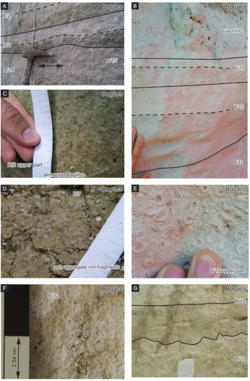
Fig. 7.Appearance of LF3 in subunit B at Bogács. A–Typical internal structure of LF3 in subunit B–coarse-grained lower part andfine-grained upper part with high amount of ash aggregates. Dashed line separates the coarse-grained lower part andfine-grained upper part in each picture. B–The contact between subunit B and C. Note the thickness difference in layer B/12 compared to picture G. C–Ash aggregates showing normal grading in the upper part of layer B/2. Scale units in centimeters. D–Layered ash aggregates in layer B/7; Note the abundant ash aggregate rim fragments. E–Upper part of layer B/12 full of layered ash aggregates withfine-grained rim and fragments. F–Small gas escape structure in layer B/12.
G–The boundary between layer B/11 and B/12. Note the abundance of ash aggregates at the top of B/11 and the faintfine bedding of B/12. Scale units in centimeters.
5.2.2. Transformation from dry fallout- to wet PDC-dominated deposition The constant thickness, the unimodal grain-size distribution (Table 2.;Lirer et al., 1973;Scasso et al., 1994;Wilson, 2001) and the well-sorted character of LF1, which is the main constituent of subunit A, imply a pyroclastic-fall origin (cf.Walker and Croasdale, 1971;
Walker, 1971). Thus, subunit A records the initial fallout-dominated phase of a Plinian eruption. The presence of LF2 indicates episodically increasing fragmentation. Alternating relatively coarse-grained (i.e.
LF1) andfine-grained (LF2) layers in stratified Plinian sequences are common, mainly attributed to intermittent collapse of the eruption col- umn (Walker, 1981b;Fierstein and Hildreth, 1992;Talbot et al., 1994;
Palladino and Taddeucci, 1998), or to the episodic transition from dry magmatic to phreatomagmatic activity for short periods of time during an ongoing eruption (Scasso et al., 1994).
The AMS data from layer 13 supports to interpret LF2 as PDC deposit.
Most of the PDC deposits show directional fabric due to the presence of shearing in the depositional regime just before the emplacement (Branney and Kokelaar, 2002;Ort et al., 2015). AMS studies of various PDC deposits pointed out, that directional fabric develops in base surge deposits (Cagnoli and Tarling, 1997), low volume confined and large volume unconfined ignimbrites (Porreca et al., 2003,Ort et al., 2003,Dedzo et al., 2011). Hence, well-clustered principal susceptibili- ties as a result of preferred-orientation of magnetic particles according to a directional fabric is considered as a general feature of PDC deposits (Cañón-Tapia and Mendoza-Borunda, 2014). From the layers analysed by AMS only layer 13 from subunit A is characterized by a preferred grain orientation, revealed by P′values of ~0.5–1.2% and good clustering of principal susceptibilies (Figs. 5, 9). Such P′values are lower, than the Fig. 8.Features of subunit C at Bogács. A–Contact between subunit B and C. Hammer length is 30 cm. B–Close-up view of the irregular, grain supported zone. Location of the close-up photographs is marked on picture A. Lacc marks a layered ash aggregate.; C–The uppermost, weathered zone of subunit C.
typical values (N2%) obtained from base surge deposits and typical ig- nimbrites with directional fabric (Cagnoli and Tarling, 1997, Dedzo et al., 2011,Ort et al., 2003). The observed vertical clustering of Kmin
and good clustering of Kmaxin an E-W subhorizontal direction is identi- cal to the“lineated and foliated”type AMS facies, which is formed, when emplacement of pyroclastic material occurs from a basal depositional system of a density-stratified current characterized by high particle con- centration compared to the overriding current (Ort et al., 2015). Alter- natively, such well-clustering of principal susceptibilities was observed from eolian sediments andfluvial resedimented materials (Tarling and Hrouda, 1993). However, in our case, deposition under heavy wind conditions or redeposition by wind is not supported by the obtained grain-size distribution showing only moderate sorting (theσφvalues as an indicator of sorting are higher than 2 from most LF2 layers). Moreover, layer 13, which was sampled for AMS analysis shows identical thickness of 25 cm both at Bogács and Tibolddaróc, and is free of signs of eolian reworking, i.e. cross-bedding and depletion offines (Smith and Katzman, 1991) or fluvial resedimentation, i.e.
cross-stratification, laminated structure (Kataoka and Nakajo, 2002;
Kataoka, 2003;Manville and Wilson, 2004).
Subunit B records a significant change in eruption style character- ized by multiple wet PDC pulses. Its PDC origin supported by the type and distribution of ash aggregates within individual layers (Table 2).
Relatively larger layered ash aggregates (0.5–1 cm in diameter) with a distinctivelyfiner-grained outer rim, are distributed sparsely in the middle part of LF3 layers. Towards the upper boundary of individual layers, such layered ash aggregates with afiner outer rim become
more abundant and typically smaller (2–5 mm in diameter). A system- atic study on the internal structure and distribution of ash aggregates found in deposits from pyroclasticflows and surges and co-ignimbrite as well as co-surge ash clouds at the Laacher See volcano showed a clear relationship between the emplacement mode of a layer and the features of ash aggregates (Schumacher and Schmincke, 1991). Namely,
“Rim-type lapilli”consisting of a coarser-grained core and an outer fine-grained rim were observed at the upper part of individual, thin PDC deposits. Besides the PDC deposits of the Laacher See volcano, the observed distribution of ash aggregates was described in the wet surge deposits of the 1982 eruption of El Chichón in Mexico (Scolamacchia et al., 2005), the thin PDC deposits of the Poris Formation at Tenerife (Brown et al., 2010) and from the normal-graded, several cm-dm thick PDC members of the 25.4 ka Oruanui eruption in New Zealand (Van Eaton and Wilson, 2013). Such beds are interpreted to be emplaced from low density, turbulent, dilute PDCs (resulting in the lower, relatively coarser-grained part), followed by fallout of ash aggre- gates from an overlying wet co-PDC ash cloud (Scolamacchia et al., 2005;Brown et al., 2010). Layered ash aggregates with afiner outer rim of the 25.4 ka Oruanui ignimbrites were originated from a hybrid cloud system with a spreading stratified column and a co-ignimbrite ash domain (Wilson, 2001;Scolamacchia et al., 2005;Van Eaton and Wilson, 2013). In this process, ash pellets formed in the vent-derived plume and reentrained into the co-PDC ash clouds, where the outer, dis- tinctivelyfiner-grained rim developed (Houghton et al., 2015b). Abun- dant ash aggregate fragments in layers of subunit B imply abrasion and/
or dismembering of ash aggregates during lateral transport within PDCs, as it was observed from several cm-dm thick phreatomagmatic PDC de- posits of the 25.4 ka Oruanui eruption (Van Eaton and Wilson, 2013;
Houghton et al., 2015b). The presence of several cm-sized gas escape structures–a common feature of laterally emplaced pyroclastic cur- rents–(Fig. 7f) in layer 12 is also consistent with a PDC origin.
In addition, the AMS measurement revealed isotropic magnetic fab- ric with P′values generally lower than 0.5% and isotropic distribution of principal susceptibilities from the middle or upper part of LF3 layers (Figs. 5 and 9). Base surge deposits and medial to distal ignimbrites are usually characterized by P′values between 2 and 10% (Cagnoli and Tarling, 1997;Ort et al., 2003) and well-clustered principal susceptibil- ities occur as a result offlow-parallel alignment of particles or imbrica- tion in the depositional regime (Branney and Kokelaar, 2002;Ort et al., 2015). Consequently, the following clustering of principal susceptibili- ties were observed: i) well-clustered vertical Kminaxes, well clustered, Kmaxaxes on the horizontal plane pointing towards theflow direction;
ii) well-clustered Kminaxes tilted away from vertical, Kmaxand Kint
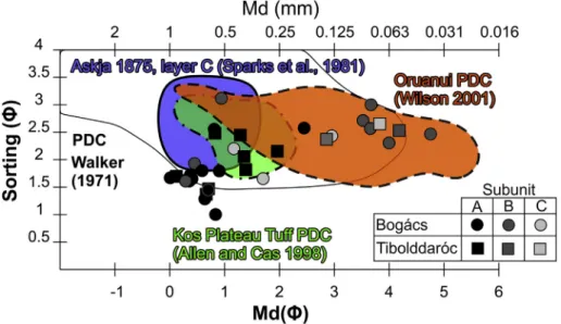
axes intermixing on a gently dipping foliation plane (see Fig. 10 in Giordano et al., 2008for further description). The emplacement of LF3 layers from low density, turbulent, dilute PDCs an overlying wet co- PDC ash cloud is further supported by the absence of such magnetic fab- ric. As a conclusion, based on these observations, we infer that subunit B was built up from multiple, dilute and wet PDC pulses. There is a transi- tional contact between subunit B and the diffusely bedded tuff of sub- unit C, which also contains the same layered ash aggregates and fragments at its base. Gas escape structures are also observed in subunit C (Fig. 8a, b), implying its PDC origin. In addition, Mdϕandσϕvalues of subunit C (specified as LF4) overlap with those of the ignimbrite of the Kos Plateau Tuff (Unit B;Allen and Cas, 1998) and thefine-grained ig- nimbrites of the 25.4 ka Oruanui eruption (Fig. 10.Self, 1983;Wilson, 2001). Thus, we infer the tuff of subunit C to be thefinal ignimbrite of the succession, emplaced from density currents generated by the col- lapse of the eruption column (Branney and Kokelaar, 2002). It is not possible to decide whether subunit C was water-rich compared to the wet PDCs of subunit B. It lacks ash aggregates at its upper part, which al- lows the following eruption scenarios: i) The closing phase of the eruptional phase that produced the ignimbrite of subunit C was dry, be- cause the external water was used up in the former phases, especially, which produced subunit B and subunit C emplaced from a relatively Fig. 9.Shape anisotropy of magnetic susceptibility ellipsoids from the Jató Member. For
location of samples and stereographic projections seeFig. 5. a) Corrected degree of anisotropy (P′) vs. mean magnetic susceptibility (Km). Note, that P′is independent from Km. b) Shape parameter (T) vs. corrected degree of anisotropy (P′) of investigated samples and various reference pyroclastic density current deposits.
dry closing PDC blast. ii) Based on itsfine grain-size similar to many ig- nimbrites of the 25.4 ka Oruanui eruption (Fig. 10,Wilson, 2001) it could be produced also by a wet PDC-generating eruption. In this case, the upper co-ignimbrite ash containing abundant ash aggregates as an indicator of the water-rich nature of the ash cloud was eroded/altered by heavy weathering. The AMS properties of subunit C are identical to LF3 (Figs. 5, 9). According to the discussion above on the lack of PDC- related magnetic fabric in subunit C, it is also suggested to be deposited from low density currents, without density stratification resulted in a basal depositional layer characterized by lateral traction (Branney and Kokelaar, 2002;Ort et al., 2015). Alternatively, low P′values can be at- tributed to very low mean susceptibilities, i.e. the scarcity of ferromag- netic particles in the samples (Rochette, 1987;Hrouda and Jelinek, 1990). Mean magnetic susceptibility of the Procida, Linosa, Pepperino Albano pyroclastic surge deposits and the Caviahue ignimbrite is be- tween 800 and 5000 × 10−6SI (Cagnoli and Tarling, 1997;Porreca et al., 2003;Ort et al., 2015). Hence, it is possible, that the existing fabric could not be revealed by AMS technique.
The abrupt change in the depositional regime from a fallout domi- nated into a collapsing column with the appearance of ash aggregates records a sudden enhancement of water vapour in the eruption column.
There are no directly observable signs of erosion or weathering within the Jató Member. This, along with the identical phenocryst assemblage of feldspar, biotite and amphibole of the entire succession implies that the member was aggraded from one single eruption event in a short pe- riod of time, possibly within hours to months. The initially sustained eruption transformed into a periodically and then fully collapsing col- umn may have resulted in the emplacement of subunit B and C due to the increased water-magma interaction at the vent (Fig. 11). Numerical experiments on column stability at a constant magma eruption rate and changing surface water content (0–40% by mass) indicated a pulsating eruption column and ascent of pyroclastic material from PDCs (i.e. di- lute PDC pulses spreading outwards from the vent zone) when a signif- icant quantity of external water was available (Van Eaton et al., 2012).
The 232 AD Taupo and the 25.4 ka Oruanui eruption in New Zealand are good analogues; in these cases, the interaction of silicic magma with a caldera lake resulted in sustained eruptions with temporarily changing water influence producing successions of fallout and PDC de- posits (Wilson, 2001, 1985,Van Eaton et al., 2012). It was documented, that ash aggregates could appear in pyroclastic successions due to en- trainment of atmospheric water into the eruptional column during pyroclast dispersal in the atmosphere (Gilbert and Lane, 1994;
Houghton et al., 2015a;White and Valentine, 2016). For example, ash
aggregates fell during the eruption of the Sakurajima on 22 May in 1983 under humid weather (Gilbert and Lane, 1994), even if, these ash aggregates lacked the outer relativelyfine-grained layers (Gilbert and Lane, 1994), thus were different from the ones observed in subunit B and C of the Jató Member. The entrainment of atmospheric water va- pour in large silicic eruptions is generally limited (Glaze and Baloga, 1996), but sometimes the eruption column is able to incorporate a high amount of atmospheric moisture due to the interaction with water-rich typhoon clouds, as it happened during the 15 June 1991 cli- mactic phase of the Pinatubo eruption (Houghton et al., 2015a). As a consequence, rain-flushing offine ash and mud rain resulting in water-saturated tephra layers were observed. Nevertheless, it is impor- tant to note thatfine-grained and layered PDC deposits from the Pinatubo eruption are free from ash aggregates and any signs of wet de- position are absent (Scott et al., 1996). Hence, the presence of ash aggre- gates in the Jató Member is more probably the result of phreatomagmatism.
5.2.3. Silicic phreatomagmatism at a subsiding back-arc basin setting The influence of external water on the eruption style progressively increased with time successively in the Jató Member. Gradual enlarge- ment of the vent area (e.g. gradual caldera subsidence) could result in a time-progressive increase of water-influence simply by letting the available surface water access to the vent via a foundering caldera. Sim- ilar increasing water-influence during the eruption was described from the Minoan Tuff (Bond and Sparks, 1976). Thefirst phase of the Minoan eruption produced plinian pumice fall, but the second and third phases were phreatomagmatic due to vent migration to the partlyflooded an- cient caldera (Heiken and McCoy, 1984;Druitt et al., 1989, 1999, 2019;
Druitt, 2014). A similar scenario is proposed for the formation of the 7.6 Ma old Akdag-Zelve ignimbrite in the Central or Cappadocian Volcanic Province (Central Anatolia; Schumacher and Mues-Schumacher, 1997). Possibly, at the BFVA, the initial dry eruptions which resulted in the aggradation of subunit A weakened the vent wall, which allowed the infiltration of sea or lake water into the vent to produce the phreatomagmatic layers of subunit B and C.
As mentioned in Section 2, the Early-Middle Miocene silicic intrabasinal volcanism of the CPR lasted for as long as 10 My (Pécskay et al., 1995, 2006). This time interval was also the time of most intense back-arc subsidence (Balázs et al., 2016), which resulted in multiple transgressions of the Central Paratethys and a continuous sea coverage in the CPR (Kováčet al., 2017). Therefore, water influence could have been a general feature of the Miocene silicic volcanism of this region.
Fig. 10.Comparison of median grain size (Mdϕ) and sorting (σϕ) of the Jató Member withfine-grained pyroclastic density current deposits published previously from Phreatoplinian successions.