1
Content from this work may be used under the terms of theCreative Commons Attribution 3.0 licence. Any further distribution of this work must maintain attribution to the author(s) and the title of the work, journal citation and DOI.
Published under licence by IOP Publishing Ltd
1234567890‘’“”
11th Hungarian Conference on Materials Science IOP Publishing
IOP Conf. Series: Materials Science and Engineering 426 (2018) 012015 doi:10.1088/1757-899X/426/1/012015
Developing a glass fibre sensor for polymer technology applications
G Hegedűs1 and T Czigány1, 2
1 Budapest University of Technology and Economics, Faculty of Mechanical Engineering, Department of Polymer Engineering, Budapest, Hungary
2 MTA–BME Research Group for Composite Science and Technology, Budapest, Hungary
E-mail: czigany@eik.bme.hu
Abstract. The goal of our research is to prove that the single-mode optical glass fibre used in telecommunications and in the optical loss test set used for the characterization of telecommunication networks is suitable for the structural health monitoring of polymer composites made from unidirectional e-glass fabric (UD). We built optical fibre into UD specimens and analysed the relationship between the power of the emitted light from the optical fibre, and the deformation of the specimen. Based on these results, a cost-effective measurement method can be achieved.
1. Introduction
Polymers are gaining in popularity and are developing fast in the 21st century. There are different kinds of polymers with different properties, but the fastest growing segment is the composites, which is used to reduce cost and mass [1]. Composites require new non-destructive test methods for structural health monitoring [2] due to their different structure from that of metals and because the matrix and reinforcement behave differently under loads [3, 4]. Several methods of structural health monitoring of composites are known, some of which use optical fibres [5]. Optical fibres are widely used to transmit digital information. Due to their advantageous properties (low mass, small size, high flexibility, heat and corrosion resistance etc.), these fibres can be easily embedded into composites of a polymer matrix [6]. As a result of external deformation, some properties of the light transmitted with the optical fibre changes [7], which can be measured with an optical instrument connected to the fibre, and therefore, the load on the structure can be identified [8, 9]. These measuring instruments are far more complicated and costly than the optical fibre itself, and optical loss test sets are widely used in the telecommunications to characterize the quality of optical networks. Attenuation (a) is the ratio of the optical power of incident light (Pi) and emitted light (Pe), expressed in decibels [10] (1):
a = 10 log Pi/Pe [dB] (1)
An optical loss test set continuously shows the attenuation of the optical fibre with reference to a reference value. The ratio of the optical power of incident and emitted light (Pi/Pe) can be easily calculated from these measured attenuation values, which shows the intensity of the emitted light in percentage, with reference to a reference value.
2
1234567890‘’“”
11th Hungarian Conference on Materials Science IOP Publishing
IOP Conf. Series: Materials Science and Engineering 426 (2018) 012015 doi:10.1088/1757-899X/426/1/012015
Our goal is to identify the deformation of a composite of a polymer matrix with the help of a general purpose optical fibre and an optical loss test set, which are widely used in the telecommunications. The intensity of light emitted by the optical fibre changes as a result of the deformation of the structure and it can be measured with an optical loss test set.
Our partial test result carries the promise of the development of a novel cost-effective polymer materials test method, and even a procedure usable in the industry.
2. Materials and methods
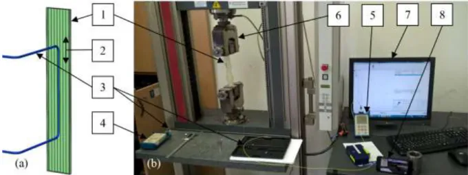
The optical fibre used is a G.652.D single-mode glass fibre of a diameter of 125 microns (Corning, USA). It has a core of a 9 micron diameter, it is sensitive to deformation and the fibre end is perpendicular. The optical fibre was tested embedded into a composite specimen, which was reinforced with unidirectional glass fabric. The coating of the fibre section which was embedded into the specimen was removed with an optical fibre stripper. The matrix around the fibre provided mechanical protection for the fibre and a stripping was performed to reduce the diameter of the fibre as much as possible in order to preserve the continuity of the composite structure. The section of the fibre outside the composite specimen was not stripped of its coating to providing some mechanical protection for the fibre. Making the specimen, we put the fibre between two layers of UD fabric, parallel to the fibre bundles (figure 1).
The matrix material was an unsaturated polyester resin (AROPOL M105 TB, Ashland S.p.A., Italy).
Initiator was added to the resin (PROMOX P200TX, PROMOX SRL, Italy) which was 1.5% of the mass of the resin.
The full length of the specimen was 250 mm and the embedded length of the optical fibre was 140 mm. The thickness of the specimens was 1.6±0.2 mm.
We used a cleaver (Fujikura, CT-30, USA) and a fibre welder (Fujikura, FSM 12 S, USA) in connecting the optical fibres. One end of the optical fibre was illuminated with a light source (AFL Telecommunications, OLS7 FTTH UCI, USA) of a wavelength of 1550 nm, and at the other end the intensity of the emitted light was measured with an optical power meter (AFL Telecommunications, OPM5-4D, USA). The optical fibre and the composite specimens were deformed in a tensile tester (Zwick, BZ050/TH3A, Germany) at a tensile speed of 0.4 mm/minute and with a clamping length of 185 mm.
Figure 1. The specimen (a) and the measurement layout (b) (1–composite specimen, 2–direction of reinforcing fibre bundles, 3-optical fibre, 4–light source, 5-optical power meter,
6-clamps of the tensile tester, 7-values measured by the tensile tester, 8-video camera)
3
1234567890‘’“”
11th Hungarian Conference on Materials Science IOP Publishing
IOP Conf. Series: Materials Science and Engineering 426 (2018) 012015 doi:10.1088/1757-899X/426/1/012015
The optical power meter cannot collect the data but displays the actual attenuation value. In order to assign the emitted light intensity of the measured displacement and force values, we recorded the values displayed by the tensile tester and the optical power meter. These recordings made it possible to connect the intensity values calculated from the attenuation values to the values had been recorded by the tensile tester.
3. Results and discussion
The goal of the tests was to prove the viability of the procedure. The optical fibre went out of the specimen in front of the clamps of the tensile tester so that the clamping did not influence the measurements. As a results of loading a change in attenuation was recorded with the above-mentioned method.
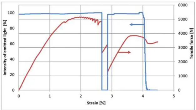
The power of emitted light showed greatly different values and tendencies during the tensile tests of various composite specimens. A characteristic measurement is shown in figure 2.
Figure 2. The relationship between the intensity of emitted light from the optical fibre and the strain of the specimen
The differences of the values appearing during the tests can be explained with the selected materials.
During the tensile test, some fibres of the UD fabric were separated from each other; some bundles were nearly broken, and others were almost unloaded. The layout of the specimen was the reason for that the individual fibre bundles had not been prestressed to the same extent and transversal bundles did not hold them together, either. The optical fibre connected to the nearby fibre bundles through the matrix. Coating of the optical fibre was removed but optical fibre-matrix adhesion was still far less than the adhesion between the fibre bundles and the matrix. When the fibres of fibre bundles had been separated from each other or had been broken, the connections between the optical fibre and the nearby fibre bundles disappeared in several tests, and even in extreme cases the optical fibre was “torn out” of the specimen.
The diagram shows that the optical fibre was connected to two fibre bundles more strongly. When the first of these fibre bundles had been broken at the strain of 2.7%, it caused the breaking of the optical fibre as well. The broken ends of the fiber moved away from each other and the optical fiber was not able to emit light. Due to the breaking of the other connected fiber bundle, the environment of the optical fiber was restored to its unloaded state from the loaded state and the broken optical fiber ends have been
4
1234567890‘’“”
11th Hungarian Conference on Materials Science IOP Publishing
IOP Conf. Series: Materials Science and Engineering 426 (2018) 012015 doi:10.1088/1757-899X/426/1/012015
reconnected again within the specimen. As a result, the power of emitted light has restored to over 98%
of incident light power. At a strain of 4%, the optical fibre was in a loaded state again. The breaking of the specimen caused the separation of the optical fibre ends permanently. The diagram shows that a load on the fibre bundle that is in connection with the optical fibre has a great influence on the power of light emitted by the optical fibre.
4. Conclusions
The tests showed that in embedding the optical fibre, the type of reinforcement the proper connection of the optical fibre and the fibre bundle must be taken into account and in this way the composite structure must be ensured. In the specimens of the tests, the optical fibre is connected to certain fibre bundles, and therefore it was able to provide information about the health of that fibre bundle (which was not the same as the health of the whole specimen). For that reason the UD reinforcement is not a good choice – the optical fibre must be connected well to the whole specimen and has to be loaded together with the structure. In spite of that fact, the test series provided some very useful results – it showed that the transmitted light power can be greatly influenced by the load, which is in connection with the health of the structural element. It can be observed as well that after loading stops, the amount of the emitted light can go back to nearly its initial value (if the optical fibre did not break as a result of loading), therefore measuring the intensity of emitted light the in-situ information about the current state of deformation can be obtained.
Acknowledgments
This research was supported by the New National Excellence Program ÚNKP-17-3-I. of the Ministry of Human Resources. The article was supported by the OTKA (K 116070 and K120592) and NVKP (NVKP_16-1-2016-0046) projects of the National Research, Development and Innovation Office (NKFIH). The authors wish to thank Péter Dobos (ATL Kft), Balázs Bartalos, Tamás Rácz and Bence Péter for their help in performing the measurements.
References
[1] Szakács J and Mészáros L 2017 Effect of fiber contents on fatigue behavior of injection molded polyamide 6 matrix composites Per. Poly. Mech. Eng. 61 6–10
[2] Hegedűs G, Sarkadi T and Czigány T 2017 Light transmission characteristic of reinforcing glass fibres used in polymer composites Materials 10 637 p9
[3] Saeed M U, Li B B, Chen Z F and Cui S 2016 Self-healing of low-velocity impact and mode-I delamination damage in polymer composites via microchannels Express Polym. Lett. 10 337- 348
[4] Muñoz-Vélez M F, Valadez-González A and Herrera-Franco P J 2017 Effect of fiber surface treatment on the incorporation of carbon nanotubes and on the micromechanical properties of a single-carbon fiber-epoxy matrix composite Express Polym. Lett. 11 704-718
[5] Gholamzadeh B and Nabovati H 2008 Fiber optic sensors. Int. J. of Electric., Comp., Energ., Electron. and Commun. Eng. 2 1107-1117
[6] Di Sante R 2015 Fibre optic sensors for structural health monitoring of aircraft composite structures: Recent advances and applications Sensors. 15 18666-18713
[7] Glisic B 2013 Distributed fiber optic sensing technologies and applications – an overview. ACI Spec. Publ. 292 1-18
[8] Glisic B and Inaudi D 2007 Fibre optic methods for structural healt monitoring John Wiley &
Sons Ltd. New York
[9] Guo H, Xiao G, Mrad N and Yao J 2011 Fiber optic sensors for structural health monitoring of air platforms Sensors 11 3687-3705
[10] Grattan K T V and Meggitt B T 1995 Optical fiber sensor technology Springer-Science+Business Media B.V, Dordrecht