85
SOFT FOLDING: A MORPHOGENETIC APPROACH TO BIO-BASED FIBROUS CONSTRUCTION MATERIALS
Máté Nagy1*, Vilmos Katona2
1József Cziráki Doctoral School of Wood Sciences and Technologies, Simonyi Károly Faculty of Engineering, Wood Sciences and Applied Arts, University of Sopron, Sopron, Hungary
2 Institute of Applied Arts, Simonyi Károly Faculty of Engineering, Wood Sciences and Applied Arts, University of Sopron, Sopron, Hungary
Abstract. Load bearing organic structures are often composed of fibrous materials. Trees that create their own structure in an architectural scale are good examples. It is no wonder trees have been a living inspiration for architecture from the very beginning. However, there is an alternative way of using fibrous materials. Cellulose, which builds trees and herbaceous plants, shows many similarities to chitin from a chemical point of view. In nature, chitin is one of the structural materials of fungi and insect exoskeletons. In addition, it is also a building material for shell structures (Vincent, 2012). Research on ultra-lightweight structures has already proven that the microstructure geometry of insect exoskeletons can be used to construct vaults built from fibrous materials (Knippers et al., 2015). Long-fibre reinforced composites have a high resistance to tensile stress but they usually perform poorly to compression and bending. Because of this, it is more practical to apply geometries that are mainly subject to tension.Our goal was to create a biocomposite structure that is tensile to the greatest possible extent. The “tensegrity”
structures bear continuous tension, and their bar elements are separately positioned in order to resist pressure (Gan, 2020). Kenneth Snelson (2012) pointed out that enveloping a tensegrity structure produces an origami form. Accordingly, one can easily turn a tensegrity framework into a folded board construction. Following this idea, several related experiments were performed. In 2012, a life-size model of a pavilion was shown, which had fixed aluminium bars covered with a textile membrane. The textile membrane was formed into a mechanically ideal shape so that we could use it as a basic form to explore new models of biocomposite construction. Hence, we followed the path of structurally ideal shapes defined by nature itself.
Keywords: tensile structure, origami, tensegrity, lightweight structures, composites, biocomposites, morphogenesis.
*Corresponding Author: Mate Nagy, Simonyi Károly Faculty of Engineering, Wood Sciences and Applied Arts, University of Sopron, 1 Cházár András tér, Sopron 9400, Hungary; Tel.: +36 30 7571042, e-mail: nagy.mate@uni-sopron.hu
Received: 3 August 2020; Accepted: 20 December 2020; Published: 30 December 2020.
1. Introduction
Load bearing structures that are organic are often composed of fibrous materials. Trees that create their own structure in an architectural scale are good examples. It is no wonder that trees have been a living inspiration for architecture from the very beginning. Morphology, structure and spatial concepts were both inspired by them, e.g., the Mosque–Cathedral of Córdoba or Antoni Gaudí’s branching pillars.
The need for a deeper understanding of bio-based structural materials motivated this present study. It is typical in the industry to adapt biomaterials to existing technologies or design strategies. At the University of Sopron, inter alia, natural fibre reinforced
86
structural biocomposites (NFRP) were manufactured for experimental purposes (fig. 1).
They were composed of hessian fabric (burlap) and a biopolymer to achieve 100% bio- based and fully biodegradable objects. After several geometrical experiments and mechanical tests, our goal was to create a morphic language based on material properties that opens the way for more structural applications.
Figure 1. Experimental products out of biocomposite
2. Architecture of folding: a historical preface
In the last century there was a revolution in architectural materials and technologies.
Designers began to abandon motif of traditional architecture on building facades. Pure building mass gained importance instead. However, architects in the first half of the 20th century continued to use traditional structural components. Mies van der Rohe worked with pillars and columns. Le Corbusier worked with rooves, facades and columns, with astonishing purism. In the meantime, the use of hybrid structures like steel and glass spread, as well as composite materials like reinforced concrete. They are resistant to bending stress in contrast to the materials of pressure architecture. The main architectural features of the 20th century evolved from these composite materials, most saliently the folded architectural mass, fluently turning from a wall to a slab, roof or pillar (Salingaros et al., 2006).
Research on economic structures began at the turn of the 19th and 20th centuries. Michell (1904) published a design method for minimal mass lattices. Furthermore, in 1917, Thompson (1992) published his work On Growth and Form, in which he stated that natural structures use the minimum material. Thompson’s work, which was based on biology, soon spread to the field of engineering. It is still popular today, and its illustrations frequently appear in studies of biomimetic design (Nagy et al., 2019).
The spread of reinforced concrete shells between the two World Wars started a renaissance of domes and vaults, such as the spectacular Zeppelin hangars at Orly Airport (1923), according the plans of Eugène Freyssinet (Xercavins et al., 2011). In 1935–36, Aimond and Lafaille had the job of designing hangars and naval workshops.
He showed that surfaces with a non-zero Gaussian curvature are highly suitable to use for thin concrete shell structures. The use of a hypar is highly recommended, since it can be covered with straight lines, which helps formwork construction (Espion, 2016).
Pioneering constructions were built according the plans of István Menyhárt in Budapest
87
during the 1930s. However, construction of hyperbolic paraboloid concrete shells began worldwide after the Second World War. Moreover, the method was instantly adapted to wood construction, since the concrete formwork is made of wood (Sutherland, 2010).
Development of lightweight construction began after World War II. Many of the most significant results were made by Frei Otto (Glaeser, 1972). He researched membranes, membrane-inspired shells and other economic structures, frequently guided by analogies from nature. Frei Otto usually composed structures out of impregnated canvas, wood, plywood, metal space trusses and cables.
3. Lightweight shells and lightweight materials
Living organisms are largely made of organic fibres. The main component of natural fibre reinforcement (hemp, linen, jute, besides other herbaceous plants) in biocomposites is cellulose. It is noteworthy that cellulose shows many chemical similarities with chitin. Only a functional molecular group distinguishes between them.
In chitin, the NH–CO–CH3 group replaces the hydroxy group of cellulose. In nature, chitin is the structural material in fungi and insect exoskeletons. In addition, it is also a building material of shell structures (Vincent, 2012). As the fibres built up from organic compounds are the main organic building materials, analogies with nature inspired the development of composite materials. Frei Otto studied diatom algae and, later at the University of Stuttgart, researchers also built folding pavilions following biomimetic inspirations (Gyulai & Katona, 2020).
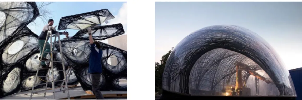
In 2011, an Echinoidea exoskeleton inspired the construction of a double layered plywood dome. The next year, they organized the fibre reinforcement of a monocoque shell based on the structure of lobster claws. Later, in 2013–14, they studied the cross section of the forward wings (elytron) of the rose chafer (Cetonia aurata), and adopted its system of multi-layered curved pillars to an FRP (Fibre Reinforced Polymer) lightweight dome. Then they made another one of plywood in 2015–16. The diving bell of a species of a spider, living underwater (Agyroneda aquatica), inspired another monocoque GFRP (Glass Fibre Reinforced Polymer) dome. In 2016–17, researchers studied the net of two silkworm species, Lyonetia clerkella and Leucoptera erythrinella, which guided the design of an FRP cantilever (Knippers et al., 2019; Schieber et al., 2015; Knippers et al., 2015; Reichert et al., 2014), (Fig. 2).
Figure 2. Research pavilion 2013–14 and 2014–15 (Knippers et al. 2019)
88
It is primarily the vehicle manufacturing industry that has used lightweight, but high performance, composite materials where they replace aluminium. Helicopter parts reinforced with glass fibre were made from 1965 for experimental purposes, but the first main structural elements were built during the 1980s. Mass production of composite parts in the 1990s was still under 10%, but after 2010 it increased to 60% in some airplanes. From the 1980s, the first tests began with primary load bearing airplane parts of carbon fibre, which was reinforced with epoxy resin. After 2000, wind turbines were constructed from GFRP (Roeseler et al., 2007). In the USA, the total volume of plastic products surpassed metal for the first time in 1979, as a result of the Oil Crisis. Since reducing the weight of vehicles reduces fuel consumption, metal parts started to be replaced by plastic parts (Gandhi & Thompson, 1992).
FRP composites began to spread in the construction industry from the second half of the 1990s. The weight of an FRP composite bridge is half that of a similar metal bridge and one-fifth that of a concrete bridge. Reducing the weight reduces the delivery and construction costs, while prefabrication reduces labour time on site. Besides, composite parts have additional advantages, like vibration tolerance, higher resistance to weather and electrical insulation.
For instance, in Harlingen (The Netherlands), the Dutch Ministry of Infrastructure and Environmental Protection (Rijkswaterstaat) initiated the installation of a fully FRP pedestrian bridge in 1997 (Fig. 3). The bridge has a U-section with reinforcing boards and was made by hand lamination. The railing provides most of the rigidity for the bridge, which is prefabricated, and was delivered to the site in one piece. The bridge consists of only one part and looks like traditional ribbed sheet metal, but is free of joints at the bridgeheads.
Bridges can be made out of pultruded composite parts as well. In Pontresina, Switzerland, there is a pedestrian bridge 25 meters long over the Flaz River. The bridge weighs 3,300 kg and has a load capacity of 500 kg/m2. The two-piece bridge was placed by helicopter on the bridgeheads and on one extra pillar under the middle of the span (fig. 4).
In Kolding, Denmark, a 40-meter-long FRP suspension bridge spans over a busy railway line, which is the first FRP bridge in the Scandinavian region. An 18.5-meter tower leans out over the asymmetric bridge and supports it with four pairs of cables. Its fasteners are made of stainless steel. Railways require fast work on site and electrical insulation. Therefore composites are emerging as an alternative to steel and concrete (Sonnenschein et al., 2016; Smits, 2016).
Figure 3. Pedestrian bridge, Harlingen, the Netherlands, made in 1997 (Smits, 2016)
Figure 4. GFRP bridge in Pontresina Bridge, Switzerland (Smits, 2016)
89 4. Architectural biocomposites
The use of organic material is part of lightweight architecture. Wood dominated the pre-industrial era. Most urban housing and many farm buildings, churches and towers were made of timber. Wattle and daub is an earth construction method, using woven wattle (a lattice of branches) to reinforce walls. Besides wood, plants were used for roofing. However, during the post-Second World War era, timber and herbaceous materials were temporary considered outdated and irrelevant, from the industrial point of view. Now a renaissance of organic industrial materials has begun.
The automotive industry widely consumes natural fibre reinforced board as interior cladding or for secondary load bearing structures, like rear shelf. Biocomposites reduce the weight of vehicles. As a result, they become quicker, more dynamic and fuel efficient. Furthermore, plant-based materials are usually cheaper (Tompson, 2013, p.
100; Alves et al., 2010).
Agricultural products are common source materials for natural fibre reinforcement, which creates a new situation. At the turn of the Millennium, the United Nations Food and Agriculture Organization (FAO). The FAO promoted research of alternative utilizations of plant fibres to create business opportunities for agricultural regions. Most of the production areas are in the Third World counties. In 2000, the International Jute Study Group (IJSG) was founded; which belongs to the economic organization of the UN. The year 2009 was dedicated as the “year of natural fibres”, and in 2010 Future Fibres was founded, which is part of the FAO and sponsored by the German Ministry of Food, Agriculture and Consumer Protection. Plant fibre production principally serves the textile industry, but alternative uses are spreading (Kozolowski et al., 2013).
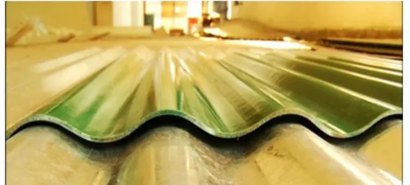
The initiated the fabrication of wide range of jute fibre-reinforced composites, e.g., suspended ceiling panels, roofing tiles, sinks, interior and exterior furniture, sanitary parts, decor materials, work safety equipment and a construction ribbed sheet, called
“Jute-tin” (Fig. 5). As its name implies, Jute-tin is a lightweight construction material and was made to replace sheet metal. It is a ribbed of a corrugated sheet (Khan & Khan, 2015).
Between 2011 and 2013, the University of Stuttgart developed a biopolymer facade system made of 90% renewable materials (Fig. 6). They built a curved horseshoe- shaped, thin shell, 145m2, bonded with metal fasteners. The result is a self-supporting building envelope, which is resistant to weather (Köhler-Hammer & Knippers, 2014).
The only built example of a biocomposite exterior load bearing structure is a bridge located on the Eindhoven Technical University campus that spans 14m over the Dommel river. Built in 2016 as an experiment, the bridge consists of a single unit made of linen and hemp filament, a reinforced bio-epoxy composite, on a core made of a Poly-Lactid Acid (PLA) polymer foam (Fig. 7). The structure was prefabricated with a unique technology and was delivered to the site in one piece. The work is part of a larger cooperation between the Technical Universities of Delft and Eindhoven, and shows the architectural use of biocomposites (Tazelaar, 2017; Smits et al., 2016).
A wood-biocomposite hybrid project was built in Stuttgard in 2018 (Fig. 8). The experimental dome is made of flexible bio-composite tapes, fixed together with plywood elements and held by three pieces of bent wooden beams. The dome has a
90
shape of a Reuleaux triangle. Besides innovative application of materials the project focuses of 3D modelling of the complex structure (Dahy et al., 2019).
Figure 5. Jute-tin (Hoque 2019) Figure 6. Biopolymer facade system (Köhler-Hammer & Knippers, 2014)
Figure 7. Biocomposite Bridge (Tazelaar, 2017)
Figure 8. Bio-Composites Experimental Pavilion (Dahy et al. 2019).
5. Utilising tensile strength
Composites, reinforced with long fibres, have higher resistance to tensile stress than compression. To attain the highest possible stability for a structure built of fibrous materials, it is necessary to bleed off as much compressive stress with tensile strain as possible. There is a similar challenge in designing vaulted structures. In that case, the solution is to factor out any strains resulting from pressure. One solution is to use catenary curves. Huygens, Leibnitz and Bernoulli first described catenary curves in 1690–91. A hanging chain always assumes this shape, which avoids any pressure until the chain is subjected to tensile stress. One can transform the ideal tensile shape into the ideal pressure shape by connecting the chain links to each other and inverting them into an arch. For instance, Antony Gaudí built an inverted model out of hanging chains for of some of his buildings to achieve this ideal geometry (Lluis i Ginovart et al., 2017).
Frei Otto also used inverted catenaries. Many halls are covered with a catenary vault, including orangeries, industrial halls, and railway stations built at the turn of the 19–20th centuries, which was the golden age of vaulted steel structures. In the present study, we aspire to design an experimental model which, similarly to the catenary vaults, produces an ideal geometry for tensile structures. Therefore, as a first step, we observe some well-known buildings and construction in which tensile strength appears as a main feature.
91
The oldest forms of tensile architecture are the tent and the suspension bridge.
Assembling tents is part of the nomadic way of life even today, but in urbanized areas tents are still important for the military, trading, circuses and temporary living. Modern tent architecture developed in the second half of the 20th century hand-in-hand with the development of lightweight architecture. There are many types of tents, but they all have in common bars, ropes and a canopy. Modern tents are used to cover large spans, such as stadiums and industrial halls. However, the aesthetic merits of tent architecture appear on public buildings as well. The spectacular roofing of the Pompidou Centre in Metz is a canopy fixed on a wooden lattice (Lewis, 2011).
The main feature of simple suspension bridges is the lack of vertical trusses; they hang from only the bridgeheads. These bridges are found mainly in mountainous areas. The availability of large amounts of inexpensive steel began the rediscovery of suspension bridge construction during the Industrial Revolution. They have been widespread from the 19th century until now, but increasingly composite components are replacing steel.
Suspension structures are also common as hall coverings. The Millennium Dome, which stands on the Greenwich Peninsula, is the best-known example since it is one of the largest covers on Earth. Unconventionally, the roofing of this building is suspended from pillars, and protrudes above the dome (Drew, 2019).
Another unconventional example is the “Blaw-Knox Tower”, which was patented in the 1930s and is also known as a diamond cantilever of a cigar antenna. Most of them were constructed in the 1930s and some of them are still in use. The structure is a steel-truss, flared at the vertical centre, which rests on a single spherical, ceramic insulator. The tower is balanced by steel wires, just like a mast. The tower can be as high as hundreds of meters (Gerten & Lindsay, 1933). Similar to suspension bridges, with bars hoisting up tensile elements which hang down from them, the cable tensioning system of the Blaw-Knox Tower balances the pillar-like central element, as an auxiliary construction.
In the case of tents, a wire and canopy supplements the hierarchic lattice system.
Figure 9. Model of a mast-like construction
92
Henceforth we will study structural concepts where tensile parts play a key role and become a primary structural element.
Figure 10. Skylon, 1951 (photo: British Official Photograph - Museum of London)
Figure 11. Moom: a tensegrity-based experimental tent 2011, Tokyo University of
Science (photo: The Japan Architect, 84)
Figure 12. Cardboard Church of Kobe, Japan, 2011. Designed and photo by Shigeru Ban
Architects.
Figure 13. Florida Suncoast Dome (Saint Petersburg, USA), 1989 (photo: Case Western
Reserve University)
6. Structure with continuous tension and discontinuous pressure
However, the use of tensegrity had prefiguration. In London, an installation more than a hundred meters high was erected for the 1951 Festival of Britain. The construction was similar to a Blaw-Knox tower, but it did not touch the ground. The lower end of the pillar was suspended from three shorter pillars. Later, a mast-like construction appeared in several architectural pieces, like the temporary cardboard church of Kobe, Japan, which opened in 2011. The canopy roof is attached to a suspended bar which hangs from the ring beam of the peristyle (Fig. 12). A similar and equally ingenious solution is a hooped cable dome system which is used for a stadium covering. The cable dome does not only consist of masts, but has a series of support hoops which hang from each other in a web of cables. One example is the Florida Suncoast Dome (Saint Petersburg, USA), built in 1989, which has a diameter of 210 meters (Robison, 1989).
93
Their common feature is bars that make an angle with the tensile elements, and they are assembled into the construction as fixtures of the cable system. The next example is an experimental construction which is noteworthy because the bar elements are on the surface of the canvas making up a homogeneous architectural mass. At the Tokyo University of Science, a tensegrity-based experimental tent was built in 2011. It is noteworthy that instead of cables, it features a 0.7 mm thick elastic polyester canopy that resists every tensile stress. The tent is 26 m long and 3.25 m high. Its largest width is 7.5 m. There are 131 aluminium tubes 25 mm in diameter that resist compression.
The innovation of the model follows that of cable domes, in which a canvas separates the interior space, which is fixed on a network of cables; but in this case, the same building component acts as a load bearing structure and a covering at the same time (s.n., 2012).
7. Soft folding
We study tensegrity because this structure subjects the materials to tension in the greatest possible extent, which is highly resisted by fibrous composites. These structures are actually trusses. However, Snelson (2012) notes, if one envelopes a tensegrity, the result will be an origami structure. In the Tokyo Pavilion, the parallel bars are fixed next to each other with a shift, producing a pattern similar to a Yoshimura fold. This makes for a functionally equal origami structure.
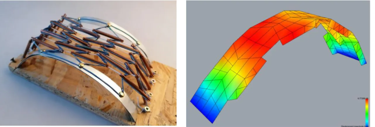
The Moom pavilion of Tokyo is a perfect study model for us, since the surface morphology is the result of the forces affecting the canopy. Initially, we decided to build a model of rubber tape and metal bars to gain a deeper understanding of the forces generated in the pavilion (Fig. 15). However, we chose to make a vault instead of a dome; in addition, a metal tape resists tensile stress of the side. The result is a tensegrity vault consisting of trapezoid fields which act like an openwork membrane. If one covers the surface, the result will be an origami structure (Fig. 16).
Figure 14. Cardboard model of the tensegrity-inspired vault
94
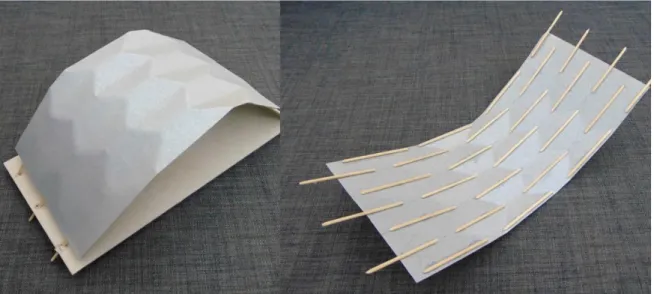
Besides, the envelope of the Tokyo Pavilion features a complex double curved surface.
Most biocomposite products are flexible sheets, which are not able to shape a double- curved surface without damage. Therefore, we make a second model, in which we replace the polyester textile with a cardboard sheet (Fig. 14).
We placed the bars on the pliant sheets, parallel to each other but with a shift. The axes of the bars form valleys like the Yoshimura pattern. The bars are not joined to each other, which produces a regular honeycomb pattern, while the sheet is lightly folded on a large radius. Hexagonal cells are bended as well and hinges smoothly bend around a radius. Besides simplifying manufacturing, an additional merit of bent sheets is that it eliminates hinges, which are weak points for an origami-inspired construction (Curletto
& Gambarotta, 2016).
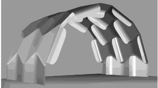
The resulting surface is particularly suitable for architectural purposes since it consists of congruent hexagons with a surface of zero Gaussian curvature. As a result, the surface is easy to modulate and foldable from a premanufactured plate, and can be pressed into a mold accordingly. Therefore, the method suits manufacturing and mechanical requirements. The bars may be made of metal, wood, bamboo or of a suitable composite material (Fig. 17).
Figure 15. Physical model of the vault representing the tensile strength of the structure
Figure 16. Displacement diagram of the finite element analysis on the geometry of the vault
8. Conclusions
In architecture, materials with different properties require a different formal language.
Traditions have developed during the long history of architecture to utilize tension resistant materials. They gain even more importance in the light of the development of recent natural materials; some of them may be used effectively for tensile architecture.
The present study proposed a method following those traditions and the technical development of the last decades. A possible way of form finding for materials with high tensile strength is based on tensegrity and origami experiments. The result is a model of a lightweight stave-shell covered with lightly folded honeycomb cells, forming an angle to each other. The cells are joined with smooth hinges, softly folding one plate to the next. Forthcoming research will clarify their exact mechanical behaviour, manufacturing and construction parameters in detail (Fig. 17).
95 References
Alves, C., Ferrao, P.M.C., Silva, A.J., Reis, L.G., Freitas, M., Rodrigues, L.B. & Alves, D.E.
(2010). Ecodesign of automotive components making use of natural jute fibre composites.
Journal of Cleaner Production, 18(4), 313–327.
Case Western Reserve University: http://www.arcaro.org/tension/album/suncoast.htm (2020.10.21.)
Curletto, G., Gambarotta, L. (2016). Design of a composed origami-inspired deployable shelter:
Modeling and technological issues. In K. Kawaguchi, M. Ohsaki and T. Takeuchi (Eds.) Proceedings of the IASS Annual Symposium 2016: “Spatial Structures in the 21st Century” [26–30 September, 2016, Tokyo, Japan], International Association for Shell and Spatial Structures (IASS) [ISSN 2518-6582], 10 p.
Dahy, H., Baszynski, P., & Petrs, J. (2019). Experimental Biocomposite Pavilion: Segmented Shell Construction - Design, Material Development, and Erection. Proceedings of ACADIA 2019: The 39th Annual Conference of the Association for Computer Aided Design in Architecture.
Drew, P. (2019). Tensile architecture, New York, NY: Taylor & Francis.
Espion, B. (2016). Pioneering hypar thin shell concrete roofs in the 1930s. Beton- und Stahlbetonbau, 111(4), 159–165.
Gan, B.S. (2019). Computational modeling of tensegrity structures: Art, nature, mechanical and biological systems. Cham, Switzerland: Springer International Publishing.
Gandhi, M.V., Thompson, B.D. (1992). Smart materials and structures, Springer Netherlands.
Gerten N. and Lindsay, J.R. (1933). “Wave antenna” [Invention], US1897373A [Filed by Blaw Knox Co., July 29, 1930].
Glaeser, L. (1972). The work of Frei Otto [Museum catalogue], New York, NY: The Museum of Modern Art. Retrieved from www.moma.org/calendar/exhibitions/2662.
Gyulai, L., Katona, V. (2020). A methodological overview of parametricism: Lessons from a case stud. Symmetry: Culture and Science, 31(3), 359–375.
Hoque, Zahirul (2019). Jute-Tin, another sustainable innovation by Dr. Mubarak, In: Textile Today: www.textiletoday.com.bd/jute-tin-another-sustainable-innovation-dr-mubarak/
(2020. 10. 21.)
Figure 17. View plan of a pavilion of folded plates
96
Khan J.A., Khan M.A. (2015). The use of juta fibres as reinforcemets in composites. In O.
Faruk and M. Sain (Eds.) Biofibre reinforcement in composite materials. Cambridge, UK:
Woodhead Publishing, pp. 30–34.
Knippers, J., La Magna R., Menges A., Reichert S., Schwinn T. and Waimer F. (2015).
ICD/ITKE Research Pavilion 2012: Coreless filament winding based on the morphological principles of an arthropod exoskeleton. Architectural Design, 85(5), 48–
53.
Knippers, J., Schmid, U. & Speck, T. (2019). Biomimetics for architecture: Learning from nature. Basel, Switzerland: Birkhäuser.
Köhler-Hammer, C., Knippers, J. (2014). Arbo Skin Fassaden-Mock up: Fassaden aus dauerhaften und rezyklierfähigen Biokunststoffen. Fassade/Façade: Schweizerische Fachzeitschrift für Fenster- und Fassadenbau, 2014(1), 9–12.
Kozlowski, R.M., Muzyczek, M. and Mackiewicz-Talarczyk, M. (2013). The coexistence and competition of natural fibres with man-made fibres and future prospects. Multi- Functional Materials and Structures, 4(747), 3–7.
Kurrer, K.E. (2008). The history of the theory of structures: From arch analysis to computational mechanics. Berlin, Germany: Ernst & Sohn.
Lewis, B. (2011). Centre Pompidou – Metz: Engineering the Roof. The Structural Engineer, 89(18), 20–25.
Lluis i Ginovart, J., Costa-Jover, A., Coll-Pla, S. & López Piquer, M. (2017). Layout of catenary arches in the Spanish Enlightenment and Modernism. Nexus Network Journal, 19(1), 85–99.
Michell, A.G.M. (1904). The limits of economy of material in frame-structures. The London, Edinburgh, and Dublin Philosophical Magazine and Journal of Science, 8(47), 589–97.
Nagy, M., Csóka, L. and Katona, V. (2019) The role of symmetry in reciprocal frame structures.
Symmetry: Culture and Science, 30(1), 15–24.
Reichert, S., Schwinn, T., La Magna, R., Waimer, F., Knippers, J., Menges, A. (2014). Fibrous structures: An integrative approach to design computation, simulation and fabrication for lightweight, glass and carbon fibre composite structures in architecture based on biomimetic design principles. Computer-Aided Design, 52, 27–39.
Robison, R. (1989). Fabric meets cable. Civil Engineering, 59(2), 56–59.
Roeseler, W.G., Sarh, B. & Kismarton, M.U. (2007). Composite structures: The first 100 years.
In Kageyama, K. et al. (Eds.) Proceedings of the 16th International Conference on Composite Materials [Kyoto, Japan, 8–13 July, 2007]. Retrieved from https://www.iccm- central.org/Proceedings/ICCM16proceedings/contents/pdf/MonA/MoAM1-
01sp_roeselerw228184p.pdf.
s. n. (2012): Moom tensegrityc membrane structure, The Japan Architect, 84, 84–85.
Salingaros, N.A., Mehaffy, M., Mikiten, T., Tejada, D. & Yu, H.S. (2006). A Theory of Architecture. Solingen, Germany: Umbau-Verlag.
Schieber, G., Koslowski, V., Knippers, J. & Menges A. (2015). Integrated design and fabrication strategies for fibrous structures. In M.R. Thomsen et al. (Eds.) Modelling Behaviour: Design Modelling Symposium 2015. Cham, Switzerland: Springer International Publishing, 237–245.
Shigeru Ban Architects: (http://www.shigerubanarchitects.com/works/1995_paper- church/index.html) (2020.10.21.)
Smits, J. (2016). Fibre-reinforced polymer bridge design in the Netherlands: Architectural challenges toward innovative, sustainable, and durable bridges. Engineering, 2(4), 518–
527.
Smits, J., Gkaidatzis, R., Blok, R., & Teuffel, P.M. (2016) Bio-based composite pedestrian bridge. Part 1: Design and optimization. In K. Kawaguchi, M. Ohsaki and T. Takeuchi (Eds.), Proceedings of the IASS Annual Symposium 2016: “Spatial Structures in the 21st Century” [26–30 September, 2016, Tokyo, Japan], International Association for Shell and Spatial Structures (IASS) [ISSN: 2518-6582], 10 p.
97
Snelson, K. (2012). The Art of Tensegrity. International Journal of Space Structures, 27(2-3), 71–80.
Sonnenschein, R., Gajdosova, K., Holly, I. (2016). FRP Composites and their using in the construction of bridges. Procedia Engineering, 161, 477–482.
Sutherland, J. (2010). Revival of structural timber in Britain after 1945. Construction History, 25, 101–113.
Tazelaar, K. (2017). Bio-Composieten: Ontwerpen met vezels en ‘bio’ polymeren [Case study
“Bio-brug”], Inholland University [ISBN: 978-90-77812-53-2]. Retrieved from https://www.inholland.nl/media/17934/k-tazelaar-_-biocomposieten-ontwerpen-met- vezels-en-bio-polymeren.pdf
Thompson, D. (1992). On Growth and Form. complete revised ed., Cambridge, UK: Cambridge University Press.
Tompson, R. (2013). Sustainable materials, processing and production. London, UK: Thames
& Hudson.
Vincent, J. (2012). Structural biomaterials. 3rd ed., Princeton, NJ: Princeton University Press.
Xercavins, P., Demarthe, D. & Shushkewich, K. (2011). Eugene Freyssinet: His incredible journey to invent and revolutionize prestressed concrete construction. In Third International fib Congress incorporating the PCI Annual Convention and Bridge Conference 2010 [29 May – 2 June, 2010, Washington, DC, USA], Chicago, IL: Precast Prestressed Concrete Institute [ISBN: 978-1-61782-821-8], pp. 1227–1254.