Keith E. Buck*
Aerojet-General Nucleonics
Subsidiary of Aerojet-General Corporation San Ramon, Calif.
Abstract
Current plans for high power level space power systems are based on the use of high-temperature, liquid-metal cooled re- actors coupled to a Rankine cycle power conversion system.
An alternate approach is the thermionic radiator concept in which similar reactors are used to supply thermal energy to
the cathodes of radiator mounted thermionic converters* The thermionic radiator system could be a backup to dynamic con- versions systems if the liquid metal cooled reactors under development are designed to satisfy the requirements of both systems« The thermionic radiator system should be considered also as the prime conversion system« Aerojet-General
Nucleonics is engaged in a program to determine the feasibili- ty of a thermionic radiator system« The primary objective of the first phase was to demonstrate the operation of a
thermionic converter, using a liquid metal to supply thermal energy to the cathode. In addition, some limited systems analysis was performed. The first phase just recently has been completed, and the objectives fully were attained.
Thermionic Radiator System System Considerations
The nuclear thermionic space power plant will be a com- pletely self-contained system producing electrical power in space. A high-temperature, liquid-metal cooled reactor will supply thermal energy to the radiator system* The thermionic
Presented at the ARS Space Power Systems Conference, Santa Monica, Calif«, September 25-28, 1962. The work described in
this paper was sponsored by the Aeronautical Systems Division, Air Research and Development Command, U. S. Air Force.
*Senior Nuclear Engineer, Space Power Projects Department.
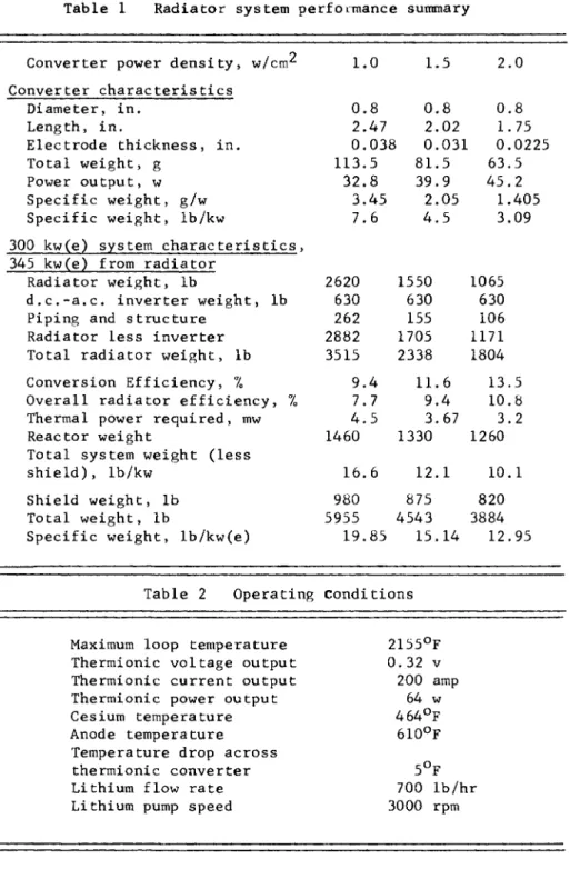
converters are built in a cylindrical geometry around the radiator tubes. Reactor heat is transferred from the heat transfer fluid to the converter cathode by conduction through the tube wall. The anode is concentric to the cathode and dissipates waste heat directly to space from its outer sur-
face and through attached fins. A typical thermionic
radiator system configuration is shown in Fig. 1, and a cross section of the converter is shown in Fig. 2.
The output voltage of a thermionic converter is 0.2 to 0.4 v when operating at optimum conditions at a cathode temperature of about 1200°C. In order to make the system output more useful, it undoubtedly will be necessary to connect many of
the converters in series. The simplest method of doing this is to connect each successive converter in series along the length of each radiator tube. The electrical potential of each converter will change according to its position on the tube, so the cathodes must be electrically insulated from the metallic liquid-metal tubing. Since heat is to be transferred from the tubing to the cathodes by conduction, the electrical insulation between the cathode and liquid metal tube also must be a good thermal conductor.
One of the most fundamental questions concerning the feasi- bility of the thermionic radiator concept was whether or not thermionic converters could be operated at temperatures achievable with liquid metal systems. Several thermionic converter types that will operate in the temperature range from 2100° to 2400°F have been investigated.
The most suitable converter concept currently available for the thermionic radiator system is the cesiated refractory metal diode. The diode consists of a refractory metal cathode and anode separated by a gap of about 10 to 20 mils.
The work function of both cathode and anode is reduced and adjusted by the cesium absorbed on the surface. In the theimionic radiator application, the cathode would operate at a work function of about 2.1 ev and the anode at about 1.5 ev. Since this converter concept is presently the most likely candidate for the thermionic radiator, the analysis of the system performance is based on the use of this device.
The thermionic radiator, when reduced to its simplest com- ponents, consists of the following: 1) liquid-metal heat
transfer fluid, 2) liquid-metal containment tube, 3) cathode insulation, 4) cathode, 5) anode, 6) cathode-anode seals, and 7) micrometeorite protection.
Dimensions and weights of the various components are re- lated closely to each other, particularly since many compo- nents serve a dual function. For example, the cathode and anode, in addition to being the emitter and collector surface for the conversion process, serve also as electrical output leads to conduct current down the length of the tube. Simi- larly, the cathode and anode function also as micrometeorite protection.
The first aim of the analysis was to define reasonable system dimensions and operating conditions. The resulting system is not necessarily optimum, but no single parameter is responsible for an inordinately high system weight.
Performance calculations in which all parameters are varied simultaneously were beyond the scope of the current analysis.
The technique used, therefore, was to vary one or two para- meters while holding the remaining system fixed. The para- meters investigated in this way include converter diameter,
converter length, electrode thickness, and seal configuration.
Estimates of reactor weight and performance are based on the concept of a fast reactor using uranium carbide fuel and liquid lithium as the coolant. The data on the reactor system presented here is drawn from work done at Aerojet- General Nucleonics on compact space power reactors for dynamic conversion systems. The lithium temperature drop through the power conversion system is more critical in a thermionic radiator system than in a Rankine cycle system, so the coolant flow rate is higher for this type of application.
The lower efficiency of thermionic conversion also tends to increase the lithium flow rate and the thermal power required from the reactor. The net result is a larger lithium pump and a slightly larger reactor. The lithium pressurizer is also larger for the thermionic radiator system, since it must compensate for the density change in the entire radiator system, as opposed to only the primary loop for a two loop dynamic system.
A plot of the weight of various subsystems as a function of converter power density is shown in Fig. 3. The effect of increased efficiency, and consequently lower thermal power requirements, at higher power densities is evident in the decrease in reactor and shield weights; however, the reduc-
tion in radiator weight is by far the most important effect of higher power density.
A plot of overall system weight is shown in Fig. 4 and Table 1 gives a summary of thermionic radiator system characteristics.
The temperature at which waste heat is rejected from the thermionic radiator has received relatively little attention in this analysis. This is due to a general lack of informa-
tion on the effect of rejection temperature on converter output. Optimum rejection temperature for the current cesiated refractory metal converters, estimated to be about 1100° to 1200°F, primarily is due to the effect of anode temperature on anode work function rather than on back emis- sion. It is reasonable to expect that a moderate amount of development work could increase rejection temperature to the range of 1300° to 1500°F with only a small consequent decrease in converter power density. This would correspond more
closely to the optimum rejection temperature for an ideal thermodynamic (Carnot) cycle.
For many applications, reliability of a space power system is more important than weight considerations. In any multi- component system, overall system reliability is a function of component reliability; system reliability may go either up or down expotentially with the number of components, depending on the effect of a component failure. In a thermionic radiator system, using a combination of series and parallel connections, the loss of a converter may mean only a slight decrease in system output; therefore, system reliability could be greater than the reliability of an individual converter. The opposite is true of dynamic systems in which nearly all components must continue to function for success- ful completion of a mission. In this case, system reliabili- ty is much lower than the reliability of individual components.
Experimental Loop Test
One of the most fundamental questions concerning the
feasibility of the thermionic radiator concept was whether or not a thermionic converter actually could be operated by using a liquid metal to supply heat to the cathode (operating
temperature is the critical parameter). In almost all previous applications, thermionic converters operated at
temperatures above the practical limit of the existing liquid metal technology.
A preliminary investigation of work being done on thermi- onic power conversion indicated that some types of converters could operate at cathode temperatures that were within the range of practical liquid metal systems, even though the primary emphasis had been on development of power systems
that would operate at high temperatures. Therefore, the most reasonable approach to the feasibility demonstration was to combine thermionic converters of a type most suitable for low
temperature operation with a liquid metal loop operating at the maximum practical temperature. For a true test of the state of the art, current technologies of thermionic power conversion and liquid metals were to be used in the demonstra- tion. The significant improvements that undoubtedly would be made by further developments in either technology was to be left for future tests.
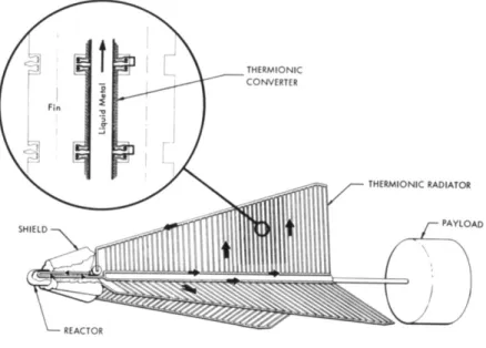
A schematic drawing of the thermionic loop is shown in Fig. 5. The system design flow rate was 700 lb/hr of lithium coolant, while the design temperature available to the
thermionic device was 2150°F. The lithium was pressurized with an inert cover gas (argon) to eliminate any possibility of boiling or cavitation. All loop components in contact with lithium were fabricated of columbium-1% zirconium alloy.
The thermionic loop design involved several basic problems.
One was how to circulate the liquid metal. The two possible approaches to this problem were 1) natural circulation and 2) forced pumping. In order to maintain a low temperature drop in the liquid metal, large flow rates were required.
With natural circulation this required a large loop and high power input. Therefore, it was decided to use forced pumping, even though this meant that mechanical energy had to be
brought into the loop either by an electromagnetic or centri- fugal pump.
Electromagnetic pumps are used to move liquid metals, but commercially available pumps of this type are limited to a maximum operating temperature of about 1600°F. If an electromagnetic pump were used in the thermionic loop, a large amount of energy (about 100 kw) would have to be removed from the lithium stream to reduce the lithium temperature to pumping temperature, and even if regenerative cooling were used, the loop would have to be large to accommodate the heat exchangers required.
Centrifugal pumps can be designed so that only the structur- al integrity of the materials of construction limits the operating temperature.
When Aerojet-General Nucleonics considered producing a centrifugal pump that would operate at temperatures close to thermionic loop temperatures for the Space Power Unit Reactor Program, it seemed advisable to combine the two programs and use the Space Power Unit Reactor pump in the thermionic loop.
The inlet temperature to the pump was to be below the thermionic converter operating temperature. A basic design problem was how to dump heat to cool the liquid metal down to
the pumping temperature then restore this heat in the heater and/or regenerator. A calculation of the number of kilowatts required indicated that a regenerative heat exchanger was needed.
There are essentially two ways be which heat can be added to a loop of this type, externally, by conduction or radia- tion to the loop, and internally, by direct ohmic heating of a part of the loop. External heating is somewhat flexible in that the electrical resistance of the heater allows lower currents to be employed than when the loop is heated directly.
However, with this type of heating, the heater element must operate at a high temperature, and the heat losses and prob- ability of heater failure become correspondingly greater.
Direct ohmic heating was used because, in spite of the
electrical current requirements, its high reliability gave the most assurance that an experiment could be conducted
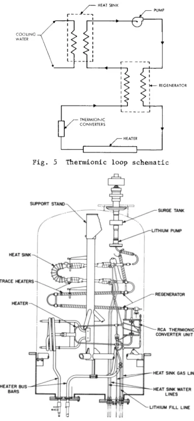
successfully. The detailed configuration of the test loop is shown in Fig. 6.
Lithium was chosen as the loop heat transfer fluid because it appears to be the fluid best suited for a space power system. Lithium has high specific heat, low density, and low vapor pressure.
Columbium-17o zirconium was chosen as the alloy for loop structural material because of its ability to contain alkali metals at high temperatures. It is one of the few refractory metals available as drawn tubing, and its fabrication
technology is relatively well established (Aerojet-General Nucleonics had previously welded and machined Cb-lZr and fabricated two corrosion loops of this material).
The disadvantage of using Cb-lZr is its high affinity for oxygen, nitrogen, hydrogen, carbon, and silicon at tempera- tures above 600°F. Relatively small amounts of these elements make the alloy brittle and lead to failure of the structure; therefore, when Cb-lZr is used at high temperature, it must be maintained carefully in an inert environment and prevented from coming in contact with these elements. The loop design provides for contact with only the high purity oxides of aluminum and zirconium or with other refractory metals that do not alloy with columbium at loop operating
temperatures.
The refractory metal of which the loop is constructed must be protected from the atmosphere at temperatures above 600°F and must therefore be housed in an enclosure in which either a pure inert gas or a high vacuum is maintained. In either
case, expensive support equipment is required. Impurities that are introduced continuously (from such components as thermal insulation) must be removed from the chamber as they are released, so that they will not contaminate the structur- al components of the loop. Air also will diffuse and leak into the chamber; these impurities can be removed by a vacuum system with a high pumping speed or by a system in which an inert gas is continuously circulated and gettered.
The vacuum environment was selected. For modest sized chambers it is less complex to construct and operate and costs less. A vacuum of about 10"6 torr is satisfactory for protecting columbium for several thousand hours and is a close simulation of the space environment.
The thermionic converter used in this test was a cesium plasma diode with a cesiated molybdenum cathode and nickel anode. The cesium plasma is maintained by impact ionization.
The cathode is 1-in. in diameter and 4-in. long, making the total cathode area about 12.6 in.2 (81 cm2). The cathode is brazed to a columbium tube (0.8-in.-diam) that is welded directly into the liquid metal loop. The ends of the molybde- num cathode tube are relieved to minimize heat loss from the cathode and to reduce the temperature at the ceramic seals.
The anode is concentric around the cathode and is separated from it by a 10 to 20 mil gap. Waste heat is rejected from the anode by radiation through fins (see Fig. 7). Cesium pressure in the cathode-anode gap is controlled by adjusting
the temperature of an external cesium reservoir. The converter was fabricated by the Electron Tube Division of RCA.
The loop was assembled with trace heaters and instrumenta- tion in place and with the thermal insulation installed. The vacuum bell jar was lowered into place, and the vacuum tank was evacuated to about 8 x 10"6 torr. The loop was trace heated to the required temperature in order to fill it with
lithium. Minimum loop temperature was held above 400°F, and maximum loop temperature was about 800 F.
The lithium had previously been loaded into a melting pot and melted and transferred through a 20-y« stainless steel filter to a gettering pot. The lithium was purified by heat- ing it in the presence of gettering materials. Titanium- zirconium chips were used to remove nitrogen, and yttrium sponge was used to remove oxygen; the lithium was held at 1200°F in the presence of these materials for about 30 hr.
The lithium then was cooled to 400°F for the filling operation.
Lithium was transferred into the loop by first evacuating the loop and then forcing the lithium into it through a second 2 0 - ^ stainless steel filter by applying argon pres- sure over the liquid in the gettering pot.
After completing the filling operation, the loop trace heaters were cut off, and the power input to the main heater was increased while the pump speed was held at 500 rpm.
During the next 1-3/4 hr the heater power and pump speed were increased until the loop temperature reached a maximum of about 2100°F, and the pump speed was 2000 rpm. A voltage was impressed across the thermionic converter by discharging a condenser across the voltage leads, and the output of the device immediately jumped from a negligible value to 25.4 w.
The temperature of the lithium supplied to the converter was increased to about 2260°F. Cesium pressure was varied slowly until the optimum value was found. At these conditions the converter produced 230 amp at 0.36 v for a power level of 82.8 w and a power density of 1.02 w/cm^.
After about an hour at 2260°F, the maximum lithium tempera- ture was lowered to about 2160°F. Cesium pressure was re-optimized, and the loop was stabilized to the conditions shown in Table 2.
The conditions shown in Table 2 were as anticipated, except that the anode temperature was much lower than expected
although this was most likely due to a defective thermocouple.
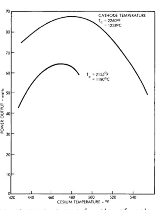
A plot of converter output as a function of cesium bulb temperature for the two cathode temperatures investigated is shown in Fig. 8. A plot of the maximum power output as a function of cathode temperature is shown in Fig. 9. The curvature indicated is based on data taken by RCA during checkout of the converter0
At the end of 18 hr the loop was shut down because of failure of the graphite face seal (used to prevent leakage of the argon cover gas from the pump). Seal failure was accompanied by the escape of a quantity of lithium into the pump roller bearing. The resultant damage to the roller bearing prevented further operation until repairs could be made.
Conclusion
The success of the thermionic loop experiment has proven the basic feasibility of the thermionic radiator concept.
However, many problems remain to be solvedo The converter power density demonstrated in this experiment is not high enough to result in a system weight comparable to dynamic systems. However, thermionic converter performance in this temperature range (2100° to 2400°F) has not been investigated intensively. It is likely that significant improvements in converter performance will be made.
System performance can be improved, even without advance- ments in thermionic technology, by increasing system tempera-
ture0 Advanced refractory metal alloys already under develop- ment may result in the increase in system temperature needed.
The work described here has the first attempt at thermionic converter operation using a liquid metal as a heat source, and was based on existing technology. It is likely that significant improvements will be made, in both converter technology and liquid metal temperature capability. Even without these improvements, the thermionic radiator concept has the advantages of high reliability and simplified develop- ment. The system deserves serious consideration as a high power level nuclear power system for use in space.
Table 1 Radiator system performance summary
Converter power density, Converter characteristics
j/cm* 1.0 1.5 2.0 Diameter, in.
Length, in.
Electrode thickness, in.
Total weight, g Power output, w Specific weight, g/w Specific weight, lb/kw
300 kw(e) system characteristics, 345 kw£el f
romradiator
0.8 2.47 0.038 113.5
32.8 3.45 7.6
0.8 2.02 0.031 81.5 39.9 2.05 4.5
0.8 1.75 0.0225 63.5 45.2
1.405 3.09
Radiator weight, lb
d.c.-a.c. inverter weight, lb Piping and structure
Radiator less inverter Total radiator weight, lb Conversion Efficiency, 7o Overall radiator efficiency, 7 Thermal power required, mw Reactor weight
Total system weight (less shield), lb/kw
Shield weight, lb Total weight, lb
Specific weight, lb/kw(e)
2620 630 262 2882 3515
9.4 7.7 4.5 1460
16.6 980 5955
19.85 1550
630 155 1705 2338 11.
9.
3.
1330 12.
875 4543 15.
.6 4
67 1
14 1065
630 106 1171 1804
13.5 10.8 3.2 1260
10.1 820 3884
12.95
Table 2 Operating conditions Maximum loop temperature
Thermionic voltage output Thermionic current output Thermionic power output Cesium temperature Anode temperature Temperature drop across thermionic converter Lithium flow rate Lithium pump speed
2155°F 0.32 v
200 amp
64 w
464°F
610°F
5°F
700 lb/hr
3000 rpm
THERMIONIC CONVERTER
THERMIONIC RADIATOR
PAYLOAD
Fig. 1 Typical thermionic radiator system
A N O D E
CATHODE - A N O D E GAP
CATHODE
ELECTRICAL I N S U L A T I O N • THERMAL B O N D
Fig. 2 Cross section of thermionic radiator unit
O l
REACTOR SYSTEM WEIGHT
1 2 CONVERTER POWER DENSITY - watts/cm2
UNSHIELDED
CO C П 7Š
CONVERTER POWER DENSITY - watts/cn
Fig. 3 Fig. 4
Major subsystem weights for 300 kw(e) thermionic Specific weight of 300 kw(e) nuclear thermionic radiator system radiator system
^-^f-
REGENERATOR
Fig. 5 Thermionic loop schematic
SUPPORT STAND
TRACE HEATERS
HEATER BUS BARS
LITHIUM PUMP
REGENERATOR
RCA THERMIONIC CONVERTER UNIT
HEAT SINK GAS LINES
HEAT SINK WATER LINES LITHIUM FILL LINE
Fig. 6 Detailed configuration of test loop
. BUCK
548
F i g .
3 40 O
CATHODE TEMPERATURE Tc = 2260°F
238°C
460 480 500 520 CESIUM TEMPERATURE - °F
Converter output as a function of cesium pressure
2200
CATHODE TEMPERATURE - °F