Experimental and Numerical Studies on Scattering from Multiple Propellers of Small UAVs
Tam´as Pet˝o, K´aroly Mar´ak, S´andor Bilicz, J´ozsef P´av´o Department of Broadband Infocommunications and Electromagnetic Theory
Budapest University of Technology and Economics, Budapest, Hungary, peto@hvt.bme.hu
Abstract—Electromagnetic scattering from propellers of small- sized Unmanned Aerial Vehicles (UAVs) is studied in this work.
Previous works have shown that rotating propeller blades pro- duce significant fluctuations of the Radar Cross Section (RCS) in the case when the propeller length is about half a wavelength of the illuminating wave. To some extent, this facilitates both the measurement of the RCS in anechoic chamber and the detection of small-sized UAVs. In the present contribution, these studies are extended to the case of multiple propellers, between which an electromagnetic coupling is expected. The scattered field and the RCS is calculated by means of electromagnetic simulation using an integral equation formulation, and the theory is validated against anechoic chamber measurements.
Index Terms—UAV detection, radar cross section, micro Doppler, integral equation
I. INTRODUCTION
In recent times, the topic of detecting small unmanned aerial vehicles (UAVs) has increasingly gained ground. Radar- based detection represents a significant direction of the current research and development works. A number of papers present specially developed system architectures that are capable of detecting small-sized UAVs [1]. Stephen Harman in [2] made efforts to examine the Doppler signature and estimate the RCS variation of the rotating propellers on multi-rotor UAVs. In his work, he considered the propeller as a conductive wire longer than half-wavelength of the illuminating signal. The frequency components belonging to the rotating propellers are clearly visible in the measured spectra at5 GHz,10 GHzand24 GHz also. However, the exact frequencies and amplitudes of these components have not yet been studied. Beyond detection, distinction from other flying objects (e.g., birds) and the classification of such devices is of great importance. In [1], measurements are shown regarding the Doppler characteristics of small sized UAVs investigated in the L-band. In their results, reflection from the rotating propellers can be clearly identified.
Besides the micro-Doppler analysis, the investigation of the resonant effects of the propellers also has significance. It has been shown in [3], that the back-scattered field of the propellers has the highest intensity near its resonant frequency.
Moreover, the unique properties of the reflected signal from the propeller facilitate the identification of the detected object.
A simulation technique for the prediction of expected spectral components has recently been proposed in [4].
While previous research focuses on the examination of a single propeller only, this paper aims to investigate the scattering properties of a propeller pair near resonant fre- quency. First, we lay down the theoretical background for the phenomenon of scattering from two rotating short propellers with lengths near the wavelength of the illuminating wave (l ∼ λ). Afterwards, we perform numerical simulations to validate theoretical predictions. Lastly, we describe scattering experiments performed in the anechoic chamber with two rotating propellers.
II. NUMERICAL MODELS FOR THE CALCULATION OF SCATTERING FROM MULTIPLE PROPELLERS
A. Theoretical overview
As shown in [4], because of the low angular velocity of their rotation (Ω ≈ 100 s−1), scattering from Carbon Fiber Reinforced Plastic (CFRP) drone propellers can be modelled using aquasi-staticapproximation; this means calculating the scattered field for static orientations of the propeller, and then interpreting the results as a sequence in time. In order to be able to compare to the measurement results (as the spectrum- analyzer measures the spectrum of the scattered field), it is then necessary to transform into the frequency domain. The rotation of the propeller modulates the scattered spectrum (the micro-Doppler effect). It has been shown, that for a rotating object illuminated by a plane wave, the spectrum of the scattered field will consist of discrete spectral components [5]:
Es(r, t) =
∞
X
m=−∞
Em(r)ej(ω+mΩ)t, (1)
whereω= 2πf0is the angular frequency of the incident EM wave andΩis the angular velocity of the propeller’s rotation.
Often times, physical optics models are preferred to solve scattering problems [6], [7], [8]; however, this method is inapplicable for shorter propellers with lengths approximately equal to the wavelength. It is therefore necessary to solve the full set of Maxwell-equations using the appropriate numerical methods.
One possible method is the Finite Element Method (FEM).
One of its disadvantages is the the associated high computa- tional cost, due to the need for volume discretization of the scatterer and its surroundings.
Another possibility is to use an integral equation method (the Method of Moments (MoM)) [9]. The usage of the MoM is advantageous for the thin propellers considered here, because a 1-dimensional discretization of the propeller is sufficient, as only the longitudinal component of the induced current is significant. As a consequence, we need to solve a problem with a much smaller number of degrees of freedom.
B. Scattering from multiple propellers
Scattering from two propellers with distance d can be computed using the quasi static method.
When two propellers 1 and 2, rotating with angular ve- locities Ω1 and Ω2, are located far enough that they can be considered being in thefar field regionof one another, so that only a weak coupling is present we can use the following approximation to compute the back-scattered spectrum:
• Calculate the (primary) spectrum of the back-scattered field generated by the currents on propeller1 induced by the illuminating wave.
• Calculate the (primary) spectrum of the field scattered in the direction of propeller2, generated by the currents on propeller1 induced by the illuminating wave.
• Calculate the (secondary) spectrum of the back-scattered field generated by the currents on propeller2 induced by the wave scattered from propeller1.
• Repeat for propellers1 and2 reversed.
• Sum the back-scattered fields at the receiver antenna it is easy to see, that the primary fields will have the form:
Es,1(r, t) =
∞
X
m=−∞
Em,1(r)ej(ω+mΩ1)t, (2)
Es,2(r, t) =
∞
X
m=−∞
Em,2(r)ej(ω+mΩ2)t. (3)
Because the field scattered from propeller1 to2 will also be modulated by the rotation of propeller2, the secondary fields will have the form:
Esecs (r, t) =
∞
X
m1=−∞
∞
X
m2=−∞
Em1,m2(r)ej(ω+m1Ω1+m2Ω2)t. (4) Since, for the inspected geometries, the rotating propellers are near to each other, we solve the problem without using the far field approximation. Herein, we solve the Electric Field Integral Equation (EFIE) for thin wires [9]:
−j ωµ
ˆt(r)·Ei(r) = ˆt(r)·
1 + 1 k2∇∇·
Z
L
I(r0)G(r,r0)dr0, (5) by decomposing the solution to sinusoidal basis on each of the propellers:
fn,i(r0) = r2
l sin
nπr0 l
, n= 1,2,3, . . .; i= 1,2 (6)
0 .2 .4 .6 .8 1
P[arbit. units]
-150 -100 -50 0 50 100 150
f-f0[Hz]
-f1 f
1 f
-f 2 2
-2f2 -2f 1 -f1-f
2 f
1+f 2
2f2 2f1
f2-f f 1
1-f 2
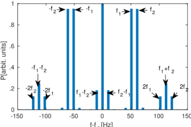
Fig. 1. Calculated spectra for a simulated scenario of two propellers at 30 cm. We can see, that alongside the base frequencies m1f1 andm2f2, m1,2= 0,±1,±2, ..., there are other frequencies present corresponding to the coupling effects between the propellers. Results are presented for the rotation frequencies off2/f1= 6/5for better readability.
Fig. 2. Anechoic chamber measurement scenario
wherer0 is the position on the propeller of lengthl such that r0 ∈[0, l]. Once the induced currents are calculated, we can then calculate the far field [4].
Results of the simulations are shown in Fig. 1. We can see, that the results obtained without any simplifying conditions are qualitatively consistent with the predictions from the far field approximation.
III. ANECHOIC CHAMBER MEASUREMENT
The direct effects of the electromagnetic coupling between the propellers have been examined by means of spectral analysis of the reflected signal using continuous wave (CW) illumination. The measurements has been performed in an anechoic chamber.
Fig. 2 illustrates the scenario used for the experimental measurement. The primary goal of the measurement was to evince and analyze the coupling effects between the propellers.
To achieve this we influenced the interaction by changing the distance between the propellers. The test bench is illustrated in Fig. 3. We used10 inchcarbon fiber propellers with a pitch of 5.8 inch. The harmonic excitation signal for the measurement
TABLE I
EXPECTED FREQUENCIES OF THE SOUGHT SPECTRAL COMPONENTS
Component Frequency
f1 86Hz
f2 147Hz
f1+f2 233Hz f2−f1 61Hz 2f1+f2 319Hz 2f2+f1 380Hz 2f1−f2 25Hz 2f2−f1 208Hz
was generated by a software defined radio and emitted with a half-wave dipole antenna. The signal reflected from the propellers is received by a similar antenna placed a small distance apart from the transmitter antenna. The frequency of the excitation signal was chosen to f = 535 MHz according to the resonant frequency of the examined propellers.
The angular velocity of the propellers is controlled remotely from a microcontroller in a way to produce easily separable and measurable spectral components. Table I summarizes the frequencies of the expected spectral components for the given propeller frequencies;f1andf2denote the frequencies of the propellers’ rotation.
Durint the experiments, the transmitter and the receiver antenna were polarized horizontally, while the rotation plane of the propellers were configured both vertically and horizontally.
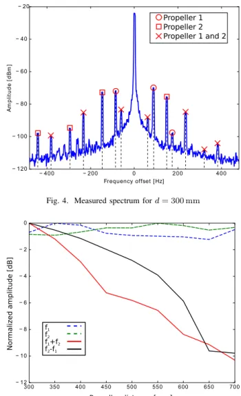
The measured spectrum ford= 300 mmis shown in Fig. 4.
The axis of the propellers’ rotation was set to be parallel with the wavevector of the incident wave. The components associated with the first propeller are marked with red squares, while the components belonging to the second propeller are marked with red circles. The identified components arising from the coupling are marked with a red cross. Among others, the exact amplitude of the sought components are dependent on the angle of incidence of the incident wave, the shape of the propeller and also on the frequency of the illuminating signal.
Fig. 5 shows the amplitude tendency of some of the identified
Fig. 3. Test bench capable of adjusting the distance between the propellers
Fig. 4. Measured spectrum ford= 300 mm
Fig. 5. Component amplitude variation as a function of propeller distanced for a for a rotation axis parallel to the wavevector of the incident wave
spectral components with increasing propeller distance. We can see that, according to our expectations, components related to the coupling have a decreasing amplitude with increasing propeller distance d. (Note that this analysis have been per- formed only for the first mixed components, which have a large enough intensity for accurate measurements.)
IV. CONCLUSION
Scattering from a pair of 10 inch propellers has been examined using a near resonant frequency excitation in the anechoic chamber. Using a weak coupling approximation, we can predict the frequencies present in the discrete backscat- tered spectrum. These results are confirmed to be qualitatively consistent with the results of rigorous calculations, as well as anechoic chamber measurements.
Future works in the topic will be centered on developing more efficient numerical models for more complicated geome- tries, and increasing the reliability of the measurements for the purpose of quantitative analysis and validation. It would also
be interesting to study how this approach opens perspectives in the radar-based detetction of multi-propeller drones.
ACKNOWLEDGMENT
The work was created in commission of the National Uni- versity of Public Service under the priority project K ¨OFOP- 2.1.2-VEKOP-15-2016-00001 titled Public Service Develop- ment Establishing Good Governance in the Bay Zolt´an Lu- dovika Workshop and was also supported by the Hungarian Scientific Research Fund under grant K-111987 and by the J´anos Bolyai Research Scholarship of the Hungarian Academy of Sciences.
REFERENCES
[1] M. Jahangir and C. J. Baker, “Extended dwell doppler characteristics of birds and micro-uas at l-band,” in 2017 18th International Radar Symposium (IRS), June 2017, pp. 1–10.
[2] S. Harman, “Characteristics of the radar signature of multi-rotor uavs,”
inRadar Conference (EuRAD), 2016 European. IEEE, 2016, pp. 93–96.
[3] T. Pet˝o, S. Bilicz, L. Sz˝ucs, S. Gyim´othy, and J. P´av´o, “The radar cross section of small propellers on unmanned aerial vehicles,” in2016 10th European Conference on Antennas and Propagation (EuCAP), April 2016, pp. 1–4.
[4] K. Mar´ak, T. Pet˝o, S. Bilicz, S. Gyim´othy, and J. P´av´o, “Electromagnetic simulation of rotating propeller blades for radar detection purposes,”IEEE Transactions on Magnetics, vol. PP, no. PP, pp. 1–4, 2018, in press.
[5] J. Van Bladel,Relativity and engineering. Springer Science & Business Media, 2012, vol. 15.
[6] V. C. Chen, F. Li, S.-S. Ho, and H. Wechsler, “Micro-Doppler effect in radar: phenomenon, model, and simulation study,”IEEE Transactions on Aerospace and Electronic systems, vol. 42, no. 1, pp. 2–21, 2006.
[7] S. Y. Yang, S. M. Yeh, S. S. Bor, S. R. Huang, and C. C. Hwang,
“Electromagnetic backscattering from aircraft propeller blades,” IEEE Transactions on Magnetics, vol. 33, no. 2, pp. 1432–1435, Mar 1997.
[8] D. Jenn and C. Ton, “Wind turbine radar cross section,”International journal of antennas and propagation, vol. 2012, 2012.
[9] W. C. Gibson,The method of moments in electromagnetics. CRC press, 2008.