Special Application of FPAA in Area of Circuit Robustness
Gy¨orgy Gy¨or¨ok, Tam´as Orosz, Margit Mak´o, Tam´as Treiber Alba Regia University Center
Obuda University´
Budai Str. 45, H-8000 Sz´ekesfeh´erv´ar
{gyorok.gyorgy, orosz.tamas, mako.margit}@arek.uni-obuda.hu, treiber.tamas@gmail.com
Abstract—In some control tasks is often necessary to ask an analog or digital solutions should be used. One way or the other choice is almost always some compromise solution is reached as a result. Suppose that any embedded micro-controller, the device is already present. This extends the resources of the micro-controller in such a way that the established arrangement is suitable for both digital and analog signal processing and control functions to implement. We do this in such a way that the established system of robust, be flexible. All this micro- controller and field programmable analog array (FPAA) is a new arrangement that has been used in the circuit from the environment can change depending on frequency of the stimulus signal.
I. INTRODUCTION
The ”robust system” or ”robustness” used to be an accepted term regarding mechanical applications, which is widely used in several disciplines. ”Robustness” as a term is often as- sociated with reliability, adaptability, error tolerance, recon- figurability sometimes with certain overlaps [7] [8] [9]. The term itself has no exact definition; generally, the measure of its quality cannot be defined. The literature uses versatile expressions such as systems of high reliability, error tol- erance, readiness to serve changed circumstances and cost effectiveness. The ”proper operation in uncertain conditions”
is the most appropriate definition [14]. A little more concrete definition is: ”operation within the error limit in unpredictable conditions” [10] [12]. The quantity and quality parameters of the ”conditions” and the measure of ”robustness” are also difficult to define [13]. According to the system approach robust equipment can be constructed from units of lower performance depending on the quality of their connection.
In this case if we can change the quality of the connection of the parts, we can further increase the quality of system robustness [11]. On the basis of the above mentioned, an electronic circuit is robust when it tolerates the stress like changes without a breakdown and, possibly, without disturbing the normal operation.
II. ROBUST ANALOG CIRCUIT SYSTEMS
An electronic system is such a multi-unit parts system where each functional unit can operate independently. This system is robust if the operation of the whole system, through the art of connecting the part units, is provided under the changed
s
µC Sin1
Sin2
Sinm
Sout1 Sout2
Soutn α1
αs
ig
β1
oz
IC
Electronic environment
FPAA β
z
i1 o1
Γ Σ
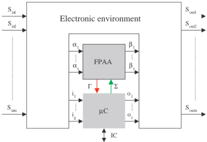
Fig. 1. Embedded micro-controller by it’s digital I/O, and a field pro- grammable analog array as a robust system.
circumstances too. The operation has to be maintained either only one or several factors exist.
This above needs can be satisfied partly by circuit redun- dancy, by over safety or by the adaptivity of the system and the scalable formation of the components. Thus the operation of the whole system can be modified by switching the part on and off, or by changing the operation parameters of the part- value. If a robust system is broken down into an appropriate number of part units, and those part units are configurable, the adaptivity and reliability of the electronic devices and equipment will significantly grow [4] [5].
The avoidance of the circuit and part unit malfunctioning is mostly a technological question, including circuit simulation- aided planning, state-of-art automated production and monitor- ing and selecting the appropriate system design technology.
III. REALIZATION OF ROBUST ANALOG CIRCUIT SYSTEMS
There is no simply solution of the robust analog circuit system to build. The latter depends on the actual component and production technology, whose development results in the reliability of circuit systems. The toleration of circuit redundancies will increase the robustness of the system just as well. To reach such system-level planning is needed where
FPAA
Dout Γ
Din
Ain Aout
µC ( A) Σ
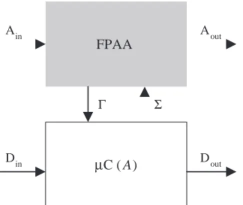
Fig. 2. Environmental embedding of a micro-controller and a programmable analog array.
the in-operation error detection, diagnosis, self-repair, self- correction, automatic system self-management are solved.
According to Fig. 1 seen, it is realized by system with embedded micro-controller, and a filed programmable analog array (FPAA). Each circuit of the system is marked with the system-level input signal (Sin1 -Sinm), and system level output are (Sout1 - Soutn) signals.
The control unit collects information about the correct operation of FPAA trough Γ surface. The embedded micro- controller (µC) connect by it’s I/O (analog or/and digital) to de controlled environmental circuit [7]. Other hand the micro- controller in the appropriate time send the next necessaries configuration information to FPAA [6]. Special solution when we try to Γsignal by interrupt art [14].
We may write down the output function in a time domain, of the one by one FPAA in the function of the input signal, it because of FPAA inner transfer function (1) used marking of Fig. 1;
βz(t) =f[αg(t),fFPAA], (1)
where; fFPAAthe current transfer function of FPAA circuit.
The transfer function of FPAA shows the equation 2;
fFPAA=f(P,n,Γ,τ), (2)
where; P is the parameter vector of the initial function of the FPAA, n is the topology description of the currently used function of the FPAA, Γ is the appropriately chosen feedback signal of the analog circuit,τ is the loop-time from IT to configuration of FPAA. All of the configuration data are described by Σsignal of Fig. 1.
From the theoretical solution of Fig. 1, can decompose the Fig. 2. This arrangement supports the increased quantity circuit functions. If we include the non-variant transfer functions in the single circuit functions too, we can see, that the circuit replacements are present in this case as well, which can be increased by raising the number of circuits [3]. All transfer
unction of the pragmatism solution of Fig. 2 can describe in equal 3;
Aout=FFPAA(Ain), (3) where;FFPAA is 4;
FFPAA=f(n,P), (4) where; n is the topology of in FPAA realized circuit (primary parameter),P is a parameter-vector, all of electronic part values (secondary parameters).
The Fig. 2 shows that the digital I/O associated only the micro-controller, so their transfer function is (5):
Dout=g(Din). (5) where;gis the algorithmically function between(Din), and (Dout).
With the digital I/O can be control all necessaries digital function’s of circuit.
IV. USING OF PROPOSED ROBUST ARRANGEMENTS
We developed, according upper mentioned micro-controller FPAA connection such robust circuit, that useful for a medical electrocardiogram device (ECG) noise filtering and able to adapt to the variable heart frequency (Fig. 3, ).
FPAA
Ain1
Primary configuration (n), Secondary Configuration (P)
Aout
µC
LCD, Switch ECG input unit
IT
signal conditioning
Fig. 3. Architecture of realized adaptive EEG input circuit as a robust electronic system.
The realized robust system consist of a PIC16F887 type micro-controller and an Anadigm AN221E04 type Dynam- ically (Field) Programable Analog Array (dpASP). These devices communicate through serial peripheral interface (SPI) bus, where a micro-controller is themasterand dpASP is the slave.
The bandpass filter was designed inAnadigmFiltersoftware.
The Primary configuration contain the topology and initial- ization parameters of the filter (Center Frequency, Pass Band Width, Stop Band Width, Pass Band Ripple, Pass Band Gain, Stop Band Attenuation) [3]. The implemented filter band pass width is 54mHz, the stop band width is 216mHz, and the stop band attenuation is 18dB. The size of Primary configuration is 132byte [1].
The dynamic reconfiguration is happen with state driven method. During the reconfiguration, the center frequency of
bandpass filter is being stepped from 0,5Hz to 4Hz in 64 steps. This create 64 piece of 35byte data array, which contains the necessary data for reconfiguration. The necessary data, for Primary and Dynamic configuration, can be generated by the AnadigmDesigner2 software [2].
After power up the stored program (Fig. 4) in the micro- controller initialize the Ports, the MSSP module for commu- nication in SPI MASTER MODE0.The SPI clock is 2MHz.
After that initialize the ECCP module in CAPCURE mode, with interrupt request on every rising edge of the incoming signal [15]. Thereafter display the power-up message on the LCD. Next send the primary configuration via the SPI inter- face, and if it was successful, then write the proper message on LCD display. Then the global interrupts are enabled [16].
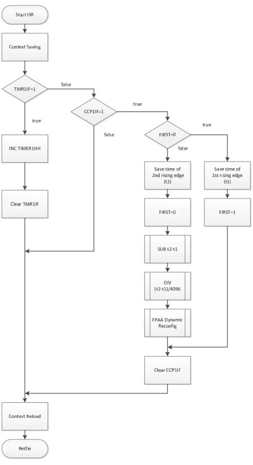
Interrupt requests are generated by every rising edge of the CCP1 input signal (Fig. 5). For measuring a 0,5Hz or a lower frequency signal, is necessary to extend the internal 16bit CAPCURE counter register to 24bit, so the micro-controller at 16MHz clock frequency can to measure 0,5Hz with 4ppm accuracy.
The measured frequency is tested in the first step, that is it included in the range from 0,5Hz till 4Hz. If it is not, then the bandpass filter will not be reconfigured [17]. If it is in the range, then it is determined by division, which dynamically reconfiguration data array should send out [18].
The primary and dynamic reconfiguration data is in the program memory of the micro-controller as Look-up tables.
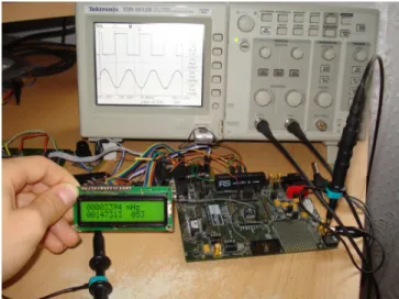
The realized circuit is seen on Fig. 6.
The measured frequency is in mHz dimension, the time elapsed between two rise edge, and the number of the re- configuration data array, can be read from the LCD display, as an extra service for success developing (Fig. 7., 8.).
V. CONCLUSIONS
In this paper, after a developed theoretical solution we have presented a useful real applications. Valuable part of our work is, that we have shown the electronic circuit and programming technology, and system components solutions.
The robust analog circuit solutions provide a consistent, high-level operation, by the cooperation of an embedded micro-controller and a programmable analog array circuit. By the mentioned solution the safety and effectiveness of the analog systems can be increased [12].
We believe that the developed method can also be used in other areas [13].
REFERENCES
[1] Programmable System-on-Chip. http://www.cypress.com/?id=1353.
[2] V´amossy, Z. Delphi a gyakorlatban (Mintafeladatok megoldssal). ZAK Kiad, Bicske, 19972000, hrom kiads
[3] Sergy´an, Sz. Content-Based Image Retrieval Using Automatically Determined Color Regions of Images. Proc. of 7th International Symposium on Applied Machine Intelligence and Informatics, Herl’any, Slovakia, January 30-31, 2009, pp. 41-45., ISBN 978-1-4244-3802-9,
IEEE Catalog Number: CFP0908E-CDR Fig. 4. Main flowchart of FPAA reconfiguration.
Fig. 5. Flowchart of adaptive tuning of FPAA based EEG filter.
Fig. 6. Interconnection of micro-controller (PIC16F887) and dynamically programmable analog array (AN221E04).
Fig. 7. Oscilloscope screen, bottom is the simulated EEG signal, upper by comparator modified square signal.
[4] ´Ad´am, T., Amadou, K., Varga A.,V´as´arhelyi, J. Active noise cancellation strategies based on digital signal processing - an overview. Engineering achievements across the global village. Radom : Printing House of the Institute for Terotechnology, 2005. p. 305-312. (The International Journal of Ingenium, ISSN 1363-514X ; 1-4.) International Conference on CAD/CAM, Robotics, and Factories of the Future (21.) (2005) (Krakow)
[5] G. Hudoba, S. Berczi. The HUNVEYOR-project - a novel way of teaching Science and Physics HSCI2011, Proceedings of the 8th Inter- national Conference os Hands-on Science, Ljubljana, Sovenia, 2011. pp.
3-6., ISBN 978-989-95095-7-3,
[6] Seebauer, M. The Role of RFID in Development of Intelligent Human
Fig. 8. Experimental environment, self developed MC-board, and a dpASP tool-kit. LCD shows the actual simulated heart-frequency.
Environment. In: Towards Intelligent Engineering and Information Technology, Springer Berlin – Heidelberg, ISBN: 978-3-642-03736-8, 457-465, Vol.:243
[7] Gy. Gy¨or¨ok. Self Organizing Analogue Circuit by Monte Carlo Method.
LINDI 2007 International Symposium on Logistics and Industrial Infor- matics September 13-15, 2007 Wildau, Germany, ISBN 1-4244-1441-5, IEEE Catalog Number 07EX1864C, Library of Congress 2007930060, p. 34–37.
[8] Gy. Gy¨or¨ok The FPAA Realization of Analog Robust Electronic Circuit.
Proc. IEEE Internacional Conference on Computational Cybernetics:
ICCC 2009. Palma de Mallorca, Spanyolorszg: pp. 1-5. Paper 10.
(ISBN:978-1-4244-5311-5) 2009.11.26-2009.11.29.
[9] Gy. Gy¨or¨ok A-class Amplifier with FPAA as a Predictive Supply Voltage Control. CINTI 2008 9th International Symposium of Hungarian Researchers on Computational Intelligence and Informatics, Budapest, Hungary. Budapest, Magyarorszg, 2008.11.06-2008.11.08. pp. 361-368.
[10] Gy. Gy¨or¨ok. Programmable Analog Circuit in Reconfigurable Systems.
5th Slovakien – Hungarien Joint Symposium on Applied Machine Intelli- gence, 2007 January 25-26, Poprad, Slovakia, ISBN 978-963-7154-56-0, p. 151–156.
[11] Gy. Gy¨or¨ok. Self Configuration Analog Circuit by FPAA. 4th Slo- vakien – Hungarien Joint Symposium on Applied Machine Intelligence, 2006 January 20-21, Herlany, Slovakia, ISBN 963 7154 44 4p. 34–37.
[12] Gy. Gy¨or¨ok. The function-controlled input for the IN CIRCUIT equip- ment. IEEE-INES2004 Intelligent, Engineering Systems Conference, Cluj-Napoca, Romania, 2004 September 19-21, INES 2004, ISBN 973- 662-120-0, p. 443–446.
[13] Gy. Gy¨or¨ok, M. Mak´o. Self configuration Analog Circuits.XVIIth Kand conference 2006 ,,In memoriam Klmn Kand” Budapest Tech Kand Klmn Faculty of Electrical Engineering, 12-14 January 2006, ISBN 963 7154 426.
[14] Gy. Gy¨or¨ok, M. Mak´o. Configuration of EEG Input-unit by Electric Circuit Evolution. INES 2005, 9th International Conference on Intel- ligent Engineering Systems, 2005 September 16-19, 2005 Cruising on Mediterranean Sea, ISBN 0-7803-9474-7, IEEE 05EX1202C.
[15] Dynamically Programable Analog Signal Processor. http://www.ana- digm.com/solutions.asp.
[16] Config data generation Anadigm App Note - 207 Application Note:
State-Driven Control of a dpASP using a Microchip PIC.
[17] Bandpass filter deging in Anadigm Filter. AnadigmDesigner2 User Manual.
[18] SPI connection between PIC and FPAA. AN121/221E04 User Manual.