T. Xu, H. Ghannam and I. Darwazeh are with the Department of Electronic and Electrical Engineering, University College London (UCL), London, WC1E 7JE, UK (e-mail: tongyang.xu.11@ucl.ac.uk, hedaia.ghannam.15@ucl.ac.uk, i.darwazeh@ucl.ac.uk). Corresponding author: Tongyang Xu.
Multipath Impairments
Tongyang Xu, Hedaia Ghannam and Izzat Darwazeh
Tongyang Xu,Member, IEEE, Hedaia Ghannam,Student Member, IEEEand Izzat Darwazeh,Senior Member, IEEE
(Invited Paper)
Abstract—The non-orthogonal signal waveform spectrally effi- cient frequency division multiplexing (SEFDM) improves spectral efficiency at the cost of self-created inter carrier interference (ICI). As the orthogonal property, similar to orthogonal fre- quency division multiplexing (OFDM), no longer exists, the robustness of SEFDM in realistic wireless environments might be weakened. This work aims to evaluate the sensitivity of SEFDM to practical channel distortions using a professional experiment testbed. First, timing offset is studied in a bypass channel to locate the imperfection of the testbed and its impact on SEFDM signals.
Then, the joint effect of a multipath frequency selective channel and additive white Gaussian noise (AWGN) is investigated in the testbed. Through practical experiments, we demonstrate the performance of SEFDM in realistic radio frequency (RF) environments and verify two compensation methods for SEFDM.
Our results show first frequency-domain compensation works well in frequency non-selective channel conditions while time- domain compensation method is suitable for frequency selective channel conditions. This work paves the way for the application of SEFDM in different channel scenarios.
Index Terms—Multicarrier, software defined radio, chan- nel compensation, spectral efficiency, OFDM, SEFDM, non- orthogonal, timing offset, testbed, experiment.
I. INTRODUCTION
A key direction in future wireless standards is to improve spectral efficiency; a quest that has been at the forefront of de- signers’ minds from the early days of wireless transmission but is acquiring urgency for today’s and future systems. A marked contribution of improving spectral efficiency was proposed in 1975 by Mazo [1], where it was proven that, in a single-carrier scenario, a 25% gain in spectral efficiency can be achieved at the same bit error rate (BER) and energy per bit (Eb).
In 2003, a multi-carrier system, termed spectrally efficient frequency division multiplexing (SEFDM) [2], [3], which improves spectral efficiency by getting the sub-carriers closer while compromising the orthogonality compared to orthogonal frequency division multiplexing (OFDM) was reported and shown to have advantages in achieving capacity gains [4], [5], choice of signal shapes and power levels [6], [7] and in coexisting with other systems [8]. Other techniques were proposed to improve spectral efficiency by suppressing the out-of-band power level, such as; generalized frequency di-
T. Xu, H. Ghannam and I. Darwazeh are with the Department of Electronic and Electrical Engineering, University College London (UCL), London, WC1E 7JE, UK (e-mail: tongyang.xu.11@ucl.ac.uk, hedaia.ghannam.15@ucl.ac.uk, i.darwazeh@ucl.ac.uk). Corresponding author:
Tongyang Xu.
vision multiplexing (GFDM) [9], filterbank based multicarrier (FBMC) [10] and universal-filtered multi-carrier (UFMC) [11].
SEFDM symbols are generated in a similar manner to OFDM with slight modifications of the inverse fast Fourier transform (IFFT) structure [12], yet they require more complex receiver structures [13]. However, with properly designed signal detection and coding schemes [14], [15], SEFDM signal can be recovered with better performance than a typical OFDM signal with the same spectral efficiency (i.e. OFDM might have higher modulation cardinality and/or higher coding rate compared to OFDM). Due to the flexible bandwidth compression benefit of SEFDM, it has been practically used in different areas, such as wireless [16], optical/mm-wave [17], visible light communication (VLC) [18], [19], optical systems [20]–[22] and internet of things (IoT) [23].
In real world wireless communication systems, radio fre- quency (RF) impairments result in signal loss and further per- formance degradation. Thus, the optimal performance obtained in an ideal simulation environment would not exist in reaility.
RF impairments include nonlinear distortions from high power amplifier (HPA); IQ imbalance; frequency offset; phase noise;
timing offset and sampling phase offset. These effects have been studied in detail in [24], [25]. Mitigation of these effects jointly is complex; the compensation for one effect could enhance the impact of others.
Fig. 1. SEFDM transceiver block diagram.
For OFDM signals, the RF impairments effects can be effi- ciently ameliorated. Unfortunately, in SEFDM, the self-created inter carrier interference (ICI) challenges the RF effects com- pensation. Taking into account the equipments used in our experimental testbed, this work investigates the compensation of timing offset and multipath frequency selective impairments in SEFDM.
The rest of the paper is organized as follows: Section II
(a)α= 1. (b)α= 0.8.
(c) α= 0.67. (d)α= 0.5.
Fig. 2. The frequency spectra of OFDM and SEFDM forN = 1024and differentα.
gives an introduction to SEFDM waveform. Section III de- scribes the experimental setup used in the evaluation. Section IV shows the measured results in a bypass channel from the experimental testbed and Section V measures results in a frequency selective channel. Finally, Section VI concludes the paper.
II. SEFDM WAVEFORM
SEFDM is defined as a multi-carrier waveform, where multiple non-orthogonal data streams are transmitted simulta- neously, such as each stream only occupies a small part of the available bandwidth. SEFDM offers possibilities of improving spectral efficiency of wired/wireless communication systems by intentionally violating the sub-carrier orthogonality [2].
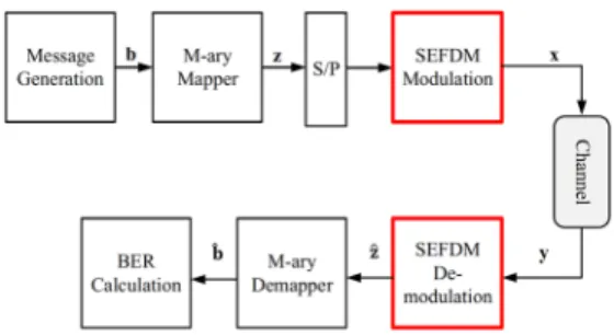
A general descriptive block diagram of an SEFDM baseband system model is given in Fig. 1. At the transmitter, the message bits b are generated and mapped into complex symbols z.
Then, the mapped symbols are divided into K streams each of size equal to the desired SEFDM symbol size N. The kth stream is converted from a serial stream to a parallel stream using a S/P converter. Afterwards, each element of this stream modulates one sub-carrier of one SEFDM symbol.
The modulated signal xk(t) is sent over a channel, then the received signalyk(t)is the input to the SEFDM demodulator, which is used to recover the transmitted symbols. Finally, a demapper retrieves the received bitsb.ˆ
Assuming Ts is the symbol interval in a single carrier system, the symbol interval in an SEFDM system ofN sub- carriers isT =N×Ts. In SEFDM, the sub-carrier spacing is
∆f=α/T where (0< α≤1) is the bandwidth compression factor andα= 1is for OFDM. The complex envelope of the
kth baseband SEFDM modulated signal can be presented by
xk(t) = 1
√T
N−1 n=0
zk,nexp (j2πnα∆f g(t−kT)). (1)
The rectangular pulse in the time-domain is translated into a Sinc-shaped sub-carrier in the frequency-domain, where Sinc(x) =Sin(πx)/(πx). A normalized SEFDM spectrum of xk(t), for N = 1024 sub-carriers and different compression levels is shown in Fig. 2. Clearly, SEFDM in Fig. 2(b-d) saves (1−α)×100%bandwidth in comparison to OFDM in Fig. 2(a) for the same transmission rate, at the expense of orthogonality violation.
SEFDM can be beneficial in another scenario by increas- ing the overall system throughput while maintaining OFDM bandwidth. The number of SEFDM sub-carriers increases to N/α, where.denotes the floor operation. Resultantly, the system throughput increases by a factor of(1−α)/α×100%. ICI in SEFDM is evident in Fig. 3. From the figure, the SEFDM signal either occupies 20% less bandwidth for the same number of sub-carriers in OFDM in Fig. 3(a), or has extra two sub-carriers within the same OFDM bandwidth, in Fig. 3(b) and (c), respectively. Another important observation by looking at Fig. 3 is that the dominant interference on a given sub-carrier comes from the main lobes of adjacent sub-carriers. Hence, ICI suppression by pulse shaping is still limited.
If the SEFDM signal in (1) were to be transmitted in additive white Gaussian noise (AWGN) channel w(t), with zero mean and variance σ2n =N0/2, whereN0 is the noise power spectral density, thekthSEFDM-received signal is
yk(t) =xk(t) +w(t). (2) Tongyang Xu,Member, IEEE, Hedaia Ghannam,Student Member, IEEEand Izzat Darwazeh,Senior
Member, IEEE (Invited Paper)
Abstract—The non-orthogonal signal waveform spectrally effi- cient frequency division multiplexing (SEFDM) improves spectral efficiency at the cost of self-created inter carrier interference (ICI). As the orthogonal property, similar to orthogonal fre- quency division multiplexing (OFDM), no longer exists, the robustness of SEFDM in realistic wireless environments might be weakened. This work aims to evaluate the sensitivity of SEFDM to practical channel distortions using a professional experiment testbed. First, timing offset is studied in a bypass channel to locate the imperfection of the testbed and its impact on SEFDM signals.
Then, the joint effect of a multipath frequency selective channel and additive white Gaussian noise (AWGN) is investigated in the testbed. Through practical experiments, we demonstrate the performance of SEFDM in realistic radio frequency (RF) environments and verify two compensation methods for SEFDM.
Our results show first frequency-domain compensation works well in frequency non-selective channel conditions while time- domain compensation method is suitable for frequency selective channel conditions. This work paves the way for the application of SEFDM in different channel scenarios.
Index Terms—Multicarrier, software defined radio, chan- nel compensation, spectral efficiency, OFDM, SEFDM, non- orthogonal, timing offset, testbed, experiment.
I. INTRODUCTION
A key direction in future wireless standards is to improve spectral efficiency; a quest that has been at the forefront of de- signers’ minds from the early days of wireless transmission but is acquiring urgency for today’s and future systems. A marked contribution of improving spectral efficiency was proposed in 1975 by Mazo [1], where it was proven that, in a single-carrier scenario, a 25% gain in spectral efficiency can be achieved at the same bit error rate (BER) and energy per bit (Eb).
In 2003, a multi-carrier system, termed spectrally efficient frequency division multiplexing (SEFDM) [2], [3], which improves spectral efficiency by getting the sub-carriers closer while compromising the orthogonality compared to orthogonal frequency division multiplexing (OFDM) was reported and shown to have advantages in achieving capacity gains [4], [5], choice of signal shapes and power levels [6], [7] and in coexisting with other systems [8]. Other techniques were proposed to improve spectral efficiency by suppressing the out-of-band power level, such as; generalized frequency di-
T. Xu, H. Ghannam and I. Darwazeh are with the Department of Electronic and Electrical Engineering, University College London (UCL), London, WC1E 7JE, UK (e-mail: tongyang.xu.11@ucl.ac.uk, hedaia.ghannam.15@ucl.ac.uk, i.darwazeh@ucl.ac.uk). Corresponding author:
Tongyang Xu.
vision multiplexing (GFDM) [9], filterbank based multicarrier (FBMC) [10] and universal-filtered multi-carrier (UFMC) [11].
SEFDM symbols are generated in a similar manner to OFDM with slight modifications of the inverse fast Fourier transform (IFFT) structure [12], yet they require more complex receiver structures [13]. However, with properly designed signal detection and coding schemes [14], [15], SEFDM signal can be recovered with better performance than a typical OFDM signal with the same spectral efficiency (i.e. OFDM might have higher modulation cardinality and/or higher coding rate compared to OFDM). Due to the flexible bandwidth compression benefit of SEFDM, it has been practically used in different areas, such as wireless [16], optical/mm-wave [17], visible light communication (VLC) [18], [19], optical systems [20]–[22] and internet of things (IoT) [23].
In real world wireless communication systems, radio fre- quency (RF) impairments result in signal loss and further per- formance degradation. Thus, the optimal performance obtained in an ideal simulation environment would not exist in reaility.
RF impairments include nonlinear distortions from high power amplifier (HPA); IQ imbalance; frequency offset; phase noise;
timing offset and sampling phase offset. These effects have been studied in detail in [24], [25]. Mitigation of these effects jointly is complex; the compensation for one effect could enhance the impact of others.
Fig. 1. SEFDM transceiver block diagram.
For OFDM signals, the RF impairments effects can be effi- ciently ameliorated. Unfortunately, in SEFDM, the self-created inter carrier interference (ICI) challenges the RF effects com- pensation. Taking into account the equipments used in our experimental testbed, this work investigates the compensation of timing offset and multipath frequency selective impairments in SEFDM.
The rest of the paper is organized as follows: Section II
(a)α= 1. (b)α= 0.8.
(c)α= 0.67. (d)α= 0.5.
Fig. 2. The frequency spectra of OFDM and SEFDM forN= 1024and differentα.
gives an introduction to SEFDM waveform. Section III de- scribes the experimental setup used in the evaluation. Section IV shows the measured results in a bypass channel from the experimental testbed and Section V measures results in a frequency selective channel. Finally, Section VI concludes the paper.
II. SEFDM WAVEFORM
SEFDM is defined as a multi-carrier waveform, where multiple non-orthogonal data streams are transmitted simulta- neously, such as each stream only occupies a small part of the available bandwidth. SEFDM offers possibilities of improving spectral efficiency of wired/wireless communication systems by intentionally violating the sub-carrier orthogonality [2].
A general descriptive block diagram of an SEFDM baseband system model is given in Fig. 1. At the transmitter, the message bits b are generated and mapped into complex symbols z.
Then, the mapped symbols are divided into K streams each of size equal to the desired SEFDM symbol size N. The kth stream is converted from a serial stream to a parallel stream using a S/P converter. Afterwards, each element of this stream modulates one sub-carrier of one SEFDM symbol.
The modulated signal xk(t) is sent over a channel, then the received signalyk(t)is the input to the SEFDM demodulator, which is used to recover the transmitted symbols. Finally, a demapper retrieves the received bitsb.ˆ
Assuming Ts is the symbol interval in a single carrier system, the symbol interval in an SEFDM system of N sub- carriers isT =N×Ts. In SEFDM, the sub-carrier spacing is
∆f=α/T where (0< α≤1) is the bandwidth compression factor andα= 1is for OFDM. The complex envelope of the
kthbaseband SEFDM modulated signal can be presented by
xk(t) = 1
√T
N−1 n=0
zk,nexp (j2πnα∆f g(t−kT)). (1)
The rectangular pulse in the time-domain is translated into a Sinc-shaped sub-carrier in the frequency-domain, where Sinc(x) =Sin(πx)/(πx). A normalized SEFDM spectrum of xk(t), forN = 1024sub-carriers and different compression levels is shown in Fig. 2. Clearly, SEFDM in Fig. 2(b-d) saves (1−α)×100%bandwidth in comparison to OFDM in Fig. 2(a) for the same transmission rate, at the expense of orthogonality violation.
SEFDM can be beneficial in another scenario by increas- ing the overall system throughput while maintaining OFDM bandwidth. The number of SEFDM sub-carriers increases to N/α, where.denotes the floor operation. Resultantly, the system throughput increases by a factor of(1−α)/α×100%.
ICI in SEFDM is evident in Fig. 3. From the figure, the SEFDM signal either occupies 20% less bandwidth for the same number of sub-carriers in OFDM in Fig. 3(a), or has extra two sub-carriers within the same OFDM bandwidth, in Fig. 3(b) and (c), respectively. Another important observation by looking at Fig. 3 is that the dominant interference on a given sub-carrier comes from the main lobes of adjacent sub-carriers.
Hence, ICI suppression by pulse shaping is still limited.
If the SEFDM signal in (1) were to be transmitted in additive white Gaussian noise (AWGN) channel w(t), with zero mean and variance σ2n =N0/2, whereN0 is the noise power spectral density, thekth SEFDM-received signal is
yk(t) =xk(t) +w(t). (2)
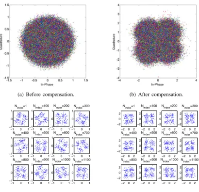
(a) Before compensation. (b) After compensation.
−1 0 1
−1 0 1
Nindex=1
−1 0 1
−1 0 1
Nindex=100
−1 0 1
−1 0 1
Nindex=200
−1 0 1
−1 0 1
Nindex=300
−1 0 1
−1 0 1
Nindex=400
−1 0 1
−1 0 1
Nindex=500
−1 0 1
−1 0 1
Nindex=600
−1 0 1
−1 0 1
Nindex=700
−1 0 1
−1 0 1
Nindex=800
−1 0 1
−1 0 1
Nindex=900
−1 0 1
−1 0 1
Nindex=1000
−1 0 1
−1 0 1
Nindex=1100
(c) Before compensation on each sub-carrier.
−2 0 2
−2 0 2
Nindex=1
−2 0 2
−2 0 2
Nindex=100
−2 0 2
−2 0 2
Nindex=200
−2 0 2
−2 0 2
Nindex=300
−2 0 2
−2 0 2
Nindex=400
−2 0 2
−2 0 2
Nindex=500
−2 0 2
−2 0 2
Nindex=600
−2 0 2
−2 0 2
Nindex=700
−2 0 2
−2 0 2
Nindex=800
−2 0 2
−2 0 2
Nindex=900
−2 0 2
−2 0 2
Nindex=1000
−2 0 2
−2 0 2
Nindex=1100
(d) After compensation on each sub-carrier.
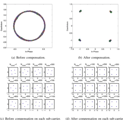
Fig. 6. Practical constellation illustrations of OFDM amplitude/phase distortions and their compensation in a bypass channel. Sub-carrier indexes are marked on each constellation sub-diagrams in (c) and (d).
A. OFDM
RF effects are studied initially by examining the OFDM constellation diagrams. Fig. 6 shows OFDM 4QAM constel- lations before and after RF effects compensation. Fig. 6(a) shows that without applying any compensation algorithms, the resultant constellation looks like a ring. There are mul- tiple reasons accounting for this constellation rotation; the first one is frequency offset, which results from unmatched transmitter/receiver local oscillators. Techniques for frequency offset correction have been elaborately studied in [28]. Other possible impairments are timing offset, phase noise, local oscillator (LO) phase offset and sampling phase errors.
A classic one-tap frequency-domain channel compensation method is employed [29] to correct the constellation rotations.
As is shown in Fig. 6(b), the rotations are corrected and four constellation points are clearly illustrated. Thus, it is proven that the testbed has no frequency offset, since frequency offset cannot be straightforwardly compensated by the one-tap frequency-domain method. However, it is difficult to separate timing offset, phase noise, LO phase offset and sampling phase error because they all introduce time independent phase offset.
To have a better understanding of the constellation rotations, a subset of 12 sub-carriers is chosen and the rotations on each may be investigated, as shown in Fig. 6(c). The FFT size in the system is 2048 in which 1200 sub-carriers are used to transmit data, the remaining sub-carriers are reserved for guard bands. In this investigation, 16 non-adjacent sub- carriers are selected with equal sub-carrier index gap, the sub-
carrier indices are thereforeNindex= 1,100,200, ...1100. Fig. 6(c) clearly shows that the phase offsets of the constellation points are different on each sub-carrier. It seems that the rotation degree is proportional to the sub-carrier index, or in other words the sub-carrier frequency. In addition, the rotation degree of the first sub-carrier is not zero, which indicates a fixed LO phase offset. It should be noted that for each sub-carrier, constellations are time independent, which further confirms that the testbed has no frequency offset. However, sampling phase offset could exist.
To correct for LO phase offset and sampling phase offset in the testbed, accurate symbol stream starting points are obtained by sample shifting of received signals. When four constellation points are clearly and properly obtained, this indicates that there neither LO phase offset nor sampling phase offset are present. If this status can not be achieved, compensation algorithms have to be employed. In the practical testbed, the estimated starting point was found to be slightly earlier than the exact starting point. Therefore, the estimated starting point was shifted to the right, achieving the required compensation. Experimenting with he number of sample shifts and their effects on the constellations is described in the sections below. 1) One Sample Shift Constellation: First, one sample is shifted and the constellation for all sub-carriers and the con- stellation for a subset of sub-carriers are illustrated in Fig. 7(a) and Fig. 7(d), respectively. We see that the rotation is mitigated slightly, but the constellation of the full signal (all sub-carriers) still resembles circle. This implies that one sample shift is not
Frequency (Hz) 0
0.2 0.4 0.6
Spectrum (Watts) 8/T
(a) OFDM,α= 1andN= 8.
Frequency (Hz) 0
0.2 0.4 0.6 0.8 1
Spectrum (Watts) 8 /T
(b) Bandwidth saving scenario, SEFDMα= 0.8andN= 8.
Frequency (Hz) 0
0.2 0.4 0.6 0.8 1
Spectrum (Watts) 8/T
(c) Throughput improvement scenario, SEFDMα = 0.8 and N= 10.
Fig. 3. OFDM and SEFDM Spectra forα= 0.8,1.
At the receiver, a coherent detector with a matched filter is used to demodulate the SEFDM signal, such as
ˆ
zk,n= 1
√T
T
0
yk(t) exp (−j2πnα∆f g(t−kT))dt, (3) where zˆk,n is the estimated symbol on the nth sub-carrier of the kth SEFDM symbol. The above symbol-by-symbol decision is no longer optimal for SEFDM, due to ICI. Thus, SEFDM detection tends to be complex.
To generate discrete SEFDM symbols, following Nyquist theorem, Q ≥ N samples are required to allow the recon- struction of the signal from its samples at the receiver. The sampled versionxk,q is
xk,q= 1
√Q
N−1 n=0
zk,nexp
j2παqn Q
, q= 0,1, ..., Q−1 where the factor1/√ (4)
Qin (4) is employed for normalization purposes. Following the same method, the discrete demodu- lated signal at the receiver side is
ˆ
zk,n= 1
√Q
Q−1
q=0
yk,qexp
−j2παqn Q
, n= 0,1, ..., N−1 (5) Taking another look at (4) and (5), they are modified versions of the inverse discrete Fourier transform (IDFT) of
Fourier transform (IFFT) and fast Fourier transform (FFT), as shown in [12]. For a detailed mathematical treatment of the ICI in SEFDM, readers are referred to [26], [27].
(a) OFDM. (b) SEFDM (α=0.8).
Fig. 4. Constellation patterns for OFDM and SEFDM signals.
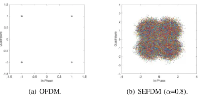
Theoretical constellation patterns are studied and compared in Fig. 4 for both OFDM and SEFDM. It is evident that OFDM shows perfect constellation points with no distortion.
However, for SEFDM, even without AWGN, the constellation is distorted significantly. The reason for this is the SEFDM self-created ICI.
III. EXPERIMENTTESTBED
Our SEFDM testbed is shown in Fig. 5. The Aeroflex PXI chassis, including a 3026C RF signal generator and a 3035C RF digitizer, plays a key role in connecting the RF environ- ment and the digital signal processors (DSP) environment. The RF signal from the 3026C RF signal generator is transmitted to the input of VR5 channel emulator where its output is connected to the 3035C RF digitizer. The spectrum analyzer, a Tektronix MDO4104-6 Mixed Domain Oscilloscope, is used to evaluate the frequency response of a signal after passing through the VR5 channel emulator.
Fig. 5. The SEFDM testbed used for the evaluation.
IV. MEASUREMENT ANDDISCUSSIONS INBYPASS
CHANNEL
A bypass channel indicates a channel without AWGN and multipath effects, such that RF effects may be studied more accurately.
(a) Before compensation. (b) After compensation.
−1 0 1
−1 0 1
Nindex=1
−1 0 1
−1 0 1
Nindex=100
−1 0 1
−1 0 1
Nindex=200
−1 0 1
−1 0 1
Nindex=300
−1 0 1
−1 0 1
Nindex=400
−1 0 1
−1 0 1
Nindex=500
−1 0 1
−1 0 1
Nindex=600
−1 0 1
−1 0 1
Nindex=700
−1 0 1
−1 0 1
Nindex=800
−1 0 1
−1 0 1
Nindex=900
−1 0 1
−1 0 1
Nindex=1000
−1 0 1
−1 0 1
Nindex=1100
(c) Before compensation on each sub-carrier.
−2 0 2
−2 0 2
Nindex=1
−2 0 2
−2 0 2
Nindex=100
−2 0 2
−2 0 2
Nindex=200
−2 0 2
−2 0 2
Nindex=300
−2 0 2
−2 0 2
Nindex=400
−2 0 2
−2 0 2
Nindex=500
−2 0 2
−2 0 2
Nindex=600
−2 0 2
−2 0 2
Nindex=700
−2 0 2
−2 0 2
Nindex=800
−2 0 2
−2 0 2
Nindex=900
−2 0 2
−2 0 2
Nindex=1000
−2 0 2
−2 0 2
Nindex=1100
(d) After compensation on each sub-carrier.
Fig. 6. Practical constellation illustrations of OFDM amplitude/phase distortions and their compensation in a bypass channel. Sub-carrier indexes are marked on each constellation sub-diagrams in (c) and (d).
A. OFDM
RF effects are studied initially by examining the OFDM constellation diagrams. Fig. 6 shows OFDM 4QAM constel- lations before and after RF effects compensation. Fig. 6(a) shows that without applying any compensation algorithms, the resultant constellation looks like a ring. There are mul- tiple reasons accounting for this constellation rotation; the first one is frequency offset, which results from unmatched transmitter/receiver local oscillators. Techniques for frequency offset correction have been elaborately studied in [28]. Other possible impairments are timing offset, phase noise, local oscillator (LO) phase offset and sampling phase errors.
A classic one-tap frequency-domain channel compensation method is employed [29] to correct the constellation rotations.
As is shown in Fig. 6(b), the rotations are corrected and four constellation points are clearly illustrated. Thus, it is proven that the testbed has no frequency offset, since frequency offset cannot be straightforwardly compensated by the one-tap frequency-domain method. However, it is difficult to separate timing offset, phase noise, LO phase offset and sampling phase error because they all introduce time independent phase offset.
To have a better understanding of the constellation rotations, a subset of 12 sub-carriers is chosen and the rotations on each may be investigated, as shown in Fig. 6(c). The FFT size in the system is 2048 in which 1200 sub-carriers are used to transmit data, the remaining sub-carriers are reserved for guard bands. In this investigation, 16 non-adjacent sub- carriers are selected with equal sub-carrier index gap, the sub-
carrier indices are thereforeNindex= 1,100,200, ...1100. Fig.
6(c) clearly shows that the phase offsets of the constellation points are different on each sub-carrier. It seems that the rotation degree is proportional to the sub-carrier index, or in other words the sub-carrier frequency. In addition, the rotation degree of the first sub-carrier is not zero, which indicates a fixed LO phase offset. It should be noted that for each sub-carrier, constellations are time independent, which further confirms that the testbed has no frequency offset. However, sampling phase offset could exist.
To correct for LO phase offset and sampling phase offset in the testbed, accurate symbol stream starting points are obtained by sample shifting of received signals. When four constellation points are clearly and properly obtained, this indicates that there neither LO phase offset nor sampling phase offset are present. If this status can not be achieved, compensation algorithms have to be employed. In the practical testbed, the estimated starting point was found to be slightly earlier than the exact starting point. Therefore, the estimated starting point was shifted to the right, achieving the required compensation.
Experimenting with he number of sample shifts and their effects on the constellations is described in the sections below.
1) One Sample Shift Constellation: First, one sample is shifted and the constellation for all sub-carriers and the con- stellation for a subset of sub-carriers are illustrated in Fig. 7(a) and Fig. 7(d), respectively. We see that the rotation is mitigated slightly, but the constellation of the full signal (all sub-carriers) still resembles circle. This implies that one sample shift is not
Frequency (Hz) 0
0.2 0.4 0.6 0.8 1
Spectrum (Watts) 8/T
(a) OFDM,α= 1andN= 8.
Frequency (Hz) 0
0.2 0.4 0.6 0.8 1
Spectrum (Watts) 8 /T
(b) Bandwidth saving scenario, SEFDMα= 0.8andN= 8.
Frequency (Hz) 0
0.2 0.4 0.6 0.8 1
Spectrum (Watts) 8/T
(c) Throughput improvement scenario, SEFDMα = 0.8and N= 10.
Fig. 3. OFDM and SEFDM Spectra forα= 0.8,1.
At the receiver, a coherent detector with a matched filter is used to demodulate the SEFDM signal, such as
ˆ
zk,n= 1
√T
T
0
yk(t) exp (−j2πnα∆f g(t−kT))dt, (3) where ˆzk,n is the estimated symbol on the nth sub-carrier of the kth SEFDM symbol. The above symbol-by-symbol decision is no longer optimal for SEFDM, due to ICI. Thus, SEFDM detection tends to be complex.
To generate discrete SEFDM symbols, following Nyquist theorem, Q ≥ N samples are required to allow the recon- struction of the signal from its samples at the receiver. The sampled versionxk,q is
xk,q= 1
√Q
N−1 n=0
zk,nexp
j2παqn Q
, q= 0,1, ..., Q−1 (4) where the factor1/√
Qin (4) is employed for normalization purposes. Following the same method, the discrete demodu- lated signal at the receiver side is
ˆ
zk,n= 1
√Q
Q−1
q=0
yk,qexp
−j2παqn Q
, n= 0,1, ..., N−1 (5) Taking another look at (4) and (5), they are modified versions of the inverse discrete Fourier transform (IDFT) of
the transmitted symbolsz and the discrete Fourier transform (DFT) of the received symbolsy, respectively. In practice, they are implemented in the digital domain by means of inverse fast Fourier transform (IFFT) and fast Fourier transform (FFT), as shown in [12]. For a detailed mathematical treatment of the ICI in SEFDM, readers are referred to [26], [27].
(a) OFDM. (b) SEFDM (α=0.8).
Fig. 4. Constellation patterns for OFDM and SEFDM signals.
Theoretical constellation patterns are studied and compared in Fig. 4 for both OFDM and SEFDM. It is evident that OFDM shows perfect constellation points with no distortion.
However, for SEFDM, even without AWGN, the constellation is distorted significantly. The reason for this is the SEFDM self-created ICI.
III. EXPERIMENTTESTBED
Our SEFDM testbed is shown in Fig. 5. The Aeroflex PXI chassis, including a 3026C RF signal generator and a 3035C RF digitizer, plays a key role in connecting the RF environ- ment and the digital signal processors (DSP) environment. The RF signal from the 3026C RF signal generator is transmitted to the input of VR5 channel emulator where its output is connected to the 3035C RF digitizer. The spectrum analyzer, a Tektronix MDO4104-6 Mixed Domain Oscilloscope, is used to evaluate the frequency response of a signal after passing through the VR5 channel emulator.
Fig. 5. The SEFDM testbed used for the evaluation.
IV. MEASUREMENT ANDDISCUSSIONS INBYPASS
CHANNEL
A bypass channel indicates a channel without AWGN and multipath effects, such that RF effects may be studied more accurately.
(a) Before compensation. (b) After compensation.
−1 0 1
−1 0 1
Nindex=1
−1 0 1
−1 0 1
Nindex=100
−1 0 1
−1 0 1
Nindex=200
−1 0 1
−1 0 1
Nindex=300
−1 0 1
−1 0 1
Nindex=400
−1 0 1
−1 0 1
Nindex=500
−1 0 1
−1 0 1
Nindex=600
−1 0 1
−1 0 1
Nindex=700
−1 0 1
−1 0 1
Nindex=800
−1 0 1
−1 0 1
Nindex=900
−1 0 1
−1 0 1
Nindex=1000
−1 0 1
−1 0 1
Nindex=1100
(c) Before compensation on each sub-carrier.
−2 0 2
−2 0 2
Nindex=1
−2 0 2
−2 0 2
Nindex=100
−2 0 2
−2 0 2
Nindex=200
−2 0 2
−2 0 2
Nindex=300
−2 0 2
−2 0 2
Nindex=400
−2 0 2
−2 0 2
Nindex=500
−2 0 2
−2 0 2
Nindex=600
−2 0 2
−2 0 2
Nindex=700
−2 0 2
−2 0 2
Nindex=800
−2 0 2
−2 0 2
Nindex=900
−2 0 2
−2 0 2
Nindex=1000
−2 0 2
−2 0 2
Nindex=1100
(d) After compensation on each sub-carrier.
Fig. 8. Practical constellation illustrations of SEFDM (α=0.8) amplitude/phase distortions and their compensation in a bypass channel.
Sub-carrier indexes are marked on each constellation sub-diagram in (c) and (d).
−15.36−3 −9.0075 0 9.0075 15.36
−2
−1 0 1 2 3
Frequency (MHz)
Magnitude
(a) OFDM.
−15.36−3 −7.206 0 7.206 15.36
−2
−1 0 1 2 3
Frequency (MHz)
Magnitude
(b) SEFDM.
Fig. 9. Spectrum of 4QAM OFDM and 4QAM SEFDM (α= 0.8) in the condition of the frequency selective channel and AWGN at SNR=36 dB.
A. OFDM Frequency-Domain Compensation
After the typical one-tap frequency-domain channel equal- ization, the frequency selective distortion is compensated and the spectrum flatness is recovered. Signals can be recovered with clear constellation points shown in Fig. 10. It should be noted that the frequency-domain and time-domain [30]
channel equalization schemes results in the same performance of OFDM. It is known that in typical OFDM systems, sub-carriers are orthogonally packed with no interference.
However, this is not the case in SEFDM since sub-carriers are non-orthogonally packed. In the following sections, both frequency-domain and time-domain equalizers for SEFDM are evaluated and compared.
0 −9.0075 0 9.0075 15.36
−3
−2
−1 0 1 2 3 4
Frequency (MHz)
Magnitude
(a) After channel equalization. (b) After compensation. Fig. 10. Spectrum and constellation of 4QAM OFDM after channel equalization in the condition of the frequency selective channel and AWGN at SNR=36 dB.
B. SEFDM Frequency-Domain Compensation
In Fig. 11(a), frequency-domain channel equalization aims to compensate the amplitude distorted spectrum in Fig. 9(b). However, this frequency-domain technique doesn’t work prop- erly since the equalized spectrum is not amplitude flat. This is because the one-tap equalizer only makes use of fractional channel information to compensate for channel distortions without considering the sub-carriers overlapping. The effects of the frequency-domain channel equalization can also be observed in Fig. 11(b) where the recovered constellations are no longer in four distinguishable regions but rather appear as a‘mixed ball’.
It is inferred that for small level of interference such as
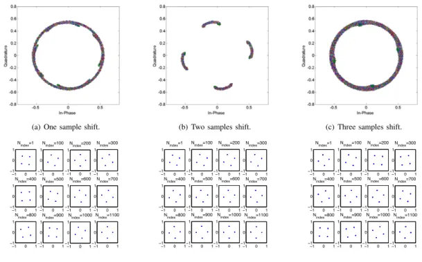
(a) One sample shift. (b) Two samples shift. (c) Three samples shift.
−1 0 1
−1 0 1
Nindex=1
−1 0 1
−1 0 1
Nindex=100
−1 0 1
−1 0 1
Nindex=200
−1 0 1
−1 0 1
Nindex=300
−1 0 1
−1 0 1
Nindex=400
−1 0 1
−1 0 1
Nindex=500
−1 0 1
−1 0 1
Nindex=600
−1 0 1
−1 0 1
Nindex=700
−1 0 1
−1 0 1
Nindex=800
−1 0 1
−1 0 1
Nindex=900
−1 0 1
−1 0 1
Nindex=1000
−1 0 1
−1 0 1
Nindex=1100
(d) One sample shift on each sub-carrier.
−1 0 1
−1 0 1
Nindex=1
−1 0 1
−1 0 1
Nindex=100
−1 0 1
−1 0 1
Nindex=200
−1 0 1
−1 0 1
Nindex=300
−1 0 1
−1 0 1
Nindex=400
−1 0 1
−1 0 1
Nindex=500
−1 0 1
−1 0 1
Nindex=600
−1 0 1
−1 0 1
Nindex=700
−1 0 1
−1 0 1
Nindex=800
−1 0 1
−1 0 1
Nindex=900
−1 0 1
−1 0 1
Nindex=1000
−1 0 1
−1 0 1
Nindex=1100
(e) Two samples shift on each sub-carrier.
−1 0 1
−1 0 1
Nindex=1
−1 0 1
−1 0 1
Nindex=100
−1 0 1
−1 0 1
Nindex=200
−1 0 1
−1 0 1
Nindex=300
−1 0 1
−1 0 1
Nindex=400
−1 0 1
−1 0 1
Nindex=500
−1 0 1
−1 0 1
Nindex=600
−1 0 1
−1 0 1
Nindex=700
−1 0 1
−1 0 1
Nindex=800
−1 0 1
−1 0 1
Nindex=900
−1 0 1
−1 0 1
Nindex=1000
−1 0 1
−1 0 1
Nindex=1100
(f) Three samples shift on each sub-carrier.
Fig. 7. Constellation illustrations of sample shift for OFDM.
sufficient to remove the effect of timing offset. In addition, it should be noted that the rotation direction in Fig. 7(d) is clockwise due to the fact that the estimated starting point of the data stream is earlier than the exact starting point of the data stream.
2) Two Samples Shift Constellation: In this part, two sam- ples are shifted to get constellation results in Fig. 7. Four points are clearly recognized with small deviations in Fig.
7(b). This indicates that the timing offset is mitigated to some degree. The deviation is caused by a fractional sample shift, in other words, sampling phase offset exists. Furthermore, checking the constellation performance on each sub-carrier, it is apparent that the rotation angle is fixed and rotation degrees for each sub-carrier are almost the same. This fixed rotation is caused by LO phase offset. Therefore, it is inferred that the experimental testbed has no frequency offset (no rotation circle on each sub-carrier); with timing offset (two samples shift or maybe random); with phase offset from local oscillators; with sampling phase offset.
3) Three Samples Shift Constellation: In order to make sure that two samples shift is optimal, Fig. 7 presents three samples shift as well. However, the constellation becomes worse again indicating that an additional timing offset is introduced by shifting three samples. furthermore, constellations of each sub- carrier are investigated showing different rotation degrees for each. It should be noted that the rotation direction in Fig. 7(f) is anti-clockwise, due to the fact that the manually shifted starting point of the data stream is one sample later than the exact starting point of the data stream.
B. SEFDM
SEFDM constellation performance is evaluated in Fig. 8, for a bandwidth compression factor ofα=0.8. Both constellation results before and after compensation are illustrated. In Fig.
8(a), the scattered constellation points result in a ‘ball’, which is totally different compared to the constellation ring shown in Fig. 6(a). By using the one-tap frequency-domain compen- sation method, the rotated constellation points are corrected as shown in Fig. 8(b). It is noted that the recovered constel- lation is very similar to the theoretical SEFDM constellation pattern in Fig. 4. This indicates that the frequency-domain compensation practically works for timing offset recovery.
After compensation, the 4QAM constellation points are not easy to recognize since they are severely affected by ICI. The interference introduced by non-orthogonal packed sub-carriers can be mitigated using the iterative interference cancellation scheme of [14].
V. MEASUREMENT ANDDISCUSSIONS INA FREQUENCY
SELECTIVECHANNEL
In this section, joint effects from both the RF parts and the frequency selective channel are investigated. Thus, the bypass channel is replaced by the frequency selective channel, which is defined in [16]. The frequency selective channel introduces both amplitude and phase distortions. The effects are illustrated in the spectra in Fig. 9. It is clearly illustrated that 20% of bandwidth is saved in SEFDM in Fig. 9(b). The remaining 80% spectrum is distorted in a similar way to that of OFDM in Fig. 9(a). We note that although SEFDM compresses signal bandwidth, the same multipath channel distortions will be applied unaffected.