SIXTH SYMPOSIUM ON BALLISTIC MISSILE AND AEROSPACE TECHNOLOGY
DIFFRACTION LIMITATIONS IN DETECTING DISTANT TARGETS BY THEIR SHADOWS
D. I . Caplan
Nortronics, A Division of Northrop Corporation Electronic Systems and Equipment Department
Palos Verdes Estates, California
ABSTRACT
In detecting a distant target by means of the shadow it casts against a stellar background, one finds that dif
fraction effects may become very severe with long ranges and small targets. The c r i t i c a l parameter for a square target is
\FL a2/ R X , where a is the length of the square, R is the range,
and Λ is the wavelength of the radiation considered. Using the Cornu spiral, one can show that (for example), in order to have at least a 90% dark shadow everywhere in the geomet
r i c a l shadow region except near the edges, \l2 a2/RX must be greater than about 8. This means that in the v i s i b l e region, for a 1-meter-square target, the range is limited to about 25 nautical miles.
INTRODUCTION
One method of detecting a distant opaque target is by means of the shadow it casts, in the v i s i b l e region of the spectrum, against a stellar background. There are many limi
tations on this method when it is used with a vidicon image tube as light sensor. One of the more fundamental limitations is the phenomenon of diffraction, which smears out the geo
metrically sharp shadow into a more diffused distribution of light. This paper is concerned only with this limitation; it should be stressed that there are more severe limitations due to the sparse nature of the stellar background and the dis
crete quantum nature of light, causing fluctuations of this
To calculate the diffraction pattern cast by a square target obscuring a star, the Huygens-Kirchhoff approximation w i l l be used. First the diffraction pattern of a square aperture is calculated in this approximation, and then Babinet!s principle is applied: the diffraction amplitude behind the square obstacle is obtained by subtracting the diffraction amplitude of the square aperture from the ampli
tude which would be present with no obstacle at a l l .
Let the side of the opaque square target be denoted by a, the wavelength of light by λ, and the range by R; then, i f a^/R λ « 1 , the range is so large that we are in the region of Fraunhofer diffraction where the diffraction pattern bears no resemblance to the shadow of geometric optics. On the other hand, i f a2/RA > > 1, then the range is so small that we are in the extreme region of Fresnel diffraction, where the diffraction pattern closely approximates the shadow of geometric optics. In between these extremes there is the transition region, which w i l l be of interest.
The Huygens-Kirchhoff integral leads to the well-known Fresnel integrals for the case of a plane wave incident normally on the square aperture. The complex amplitude of wavelength λ is given by the expression (1 ) :
(x - a/2)V RA/2 (y -"a/2)>/ RA/2
where χ and y are the cartesian coordinates, in a plane paral l e i to the aperture at a range R, with origin directly behind the center of the square, and A is the amplitude of the inci
dent plane wave. Both these integrals are obtainable from the Cornu spiral. In the limit a—» » , i . e . , no obstacle at a l l , each integral is equal to (1 + i ) , the complex vector from one apex to the other on the Cornu s p i r a l . Thus, for infinitely wide aperture:
0( x , y ) = - i A/ 2 (1 + i ) (1 + i ) = A (2)
Hence, for the square obstacle, Babinet's principle yields:
(x + a/2)\L RA/2 (y + a/ 2 \ T R X 7 2
(1)
φ ( x , y ) = A (1 + i/ 2 F F ) (3)
where
SIXTH SYMPOSIUM ON BALLISTIC MISSILE AND AEROSPACE TECHNOLOGY
(x + a/2)>/ RA/2
(x - a/2) N/ R X/ 2
(y +
a/2) si
RA/2Fy - j ei 7 T v 2 / 2 dV (y - a/2)</]RA/2
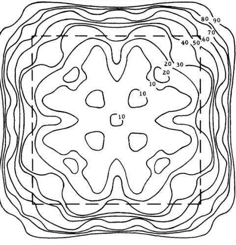
The parameter WRX/2, or V 2a2/R^ , determines the nature of the diffraction pattern, since the limits of integration, for a l l χ and y, are separated by this amount. Figures 1 through 5 illustrate the various results obtained from Equation ( 3 ) . Note the absence of the "Poisson bright spot11
(2) from the center of the diffraction pattern for the square;
this spot is present in the case of the circular obstacle.
CIRCULAR TARGET
Except for the central Poisson bright spot, the diffrac
tion pattern for the circular obstacle is expected to be very much like that of the square, as far as the extent of the
fuzziness of the shadow is concerned.
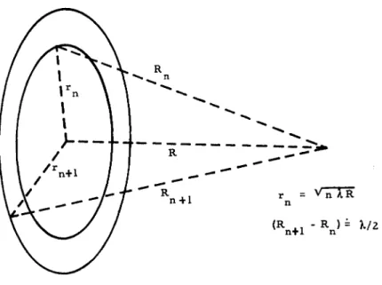
To calculate the complex light amplitude without obstacle in the Fresnel region, we proceed with the idea of Fresnel zones. A wide-open aperture is subdivided into circles of radii V nAR , where η = integer, λ = wavelength, and R = distance from plane of aperture to observer. See Figure 6.
The resultant light amplitudes coming from adjacent rings are about 180 degrees out of phase with one another. However, as one progresses from inner to outer rings, the amplitude de
creases to zero due to "obliquity factor" and "inverse square"
law (actually inverse first power for amplitude). Thus, adding these vectors, we find that the resultant is just one-half as large as the largest arrow. See Figure 7.
The disturbance due to the center of the central Fresnel zone is just 180 degrees out of phase with that due to the periphery of the central zone. Thus, the net disturbance
Fig. 1. Isophotes 2a /RA = 64.
Wavelength 0.6μ; Target 1 sq m; Range 25 η mi; Intensity of Incident Beam 100; Dotted Square Represents Geometrical Shadow
SIXTH SYMPOSIUM ON BALLISTIC MISSILE AND AEROSPACE TECHNOLOGY
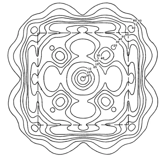
Fig. 2. Isophotes 2a /RA = 16. 9
Range 100 η mi
Fig. 3. Isophotes 2a /RA = 8.
Range 200 η mi
SIXTH SYMPOSIUM ON BALLISTIC MISSILE AND AEROSPACE TECHNOLOGY
Fig. 4. Isophotes 2a /RA = 3, Range 550 η mi
ο
F i g . 5. Isophotes 2a / R A = 1.
Range 1600 η mi
SIXTH SYMPOSIUM ON BALLISTIC MISSILE AND AEROSPACE TECHNOLOGY
Fig. 6. Construction of Fresnel Zones.
+ + j + | + j + J + j + J + f + | + · · ·
Fig. 7. Vector Addition for Wide-Open Aperture.
Fig. 8. Vector Addition for Circular Aperture.
Fig. 9. Vector Subtraction for Circular Obstacle.
M f ··· +1+T+ (*c* \ c
Fig. 10. Vector Addition for Circular Aperture.
Fig. 11. Vector Subtraction for Circular Obstacle.
Β
SIXTH SYMPOSIUM ON BALLISTIC MISSILE AND AEROSPACE .TECHNOLOGY
obtained by this method seems 90 degrees ahead of the phase of the center of the aperture's disturbance, and this Fresnel zone method has overlooked a 90-degree phase shift; i . e . , the factor ( - i ) of Equation ( 1 ) .
Now, if we want to describe the disturbance in the Fres
nel region, r > > RA (many zones subtended), on the axis of a circular aperture of arbitrary radius rQ, we do as above for the wide-open aperture. Note, however, that the pre
viously infinite series is now finite and, for reasonably small apertures observed at large distances, say rQ/ R £ l / 5 radian, each term--except the last one where only a fraction of a zone may be included—is of approximately equal magnitude and is directed vertically up or down in the complex plane.
(Note that if R is so large that only a fraction of a zone is subtended at a l l , we are in the Fraunhofer region.)
The last term, however, is more complicated. Assume for definiteness that the next-to-last term is directed downward.
Then the locus of the termination point of the arrow for the last term is a semicircle, as shown in Figure 8, with diameter equal to the other vertical vectors. (This is due to the fact that the last zone may be subdivided into smaller zones, each contributing the same amplitude but progressively different phases, thus producing a circle of diameter such that if the zone is complete the result must be the same as for one com
plete zone.) Since a l l but the very last term cancel out, the net disturbance from the aperture is somewhere along this semicircle.
Now we progress to the case of the axis of the circular obstacle. The net observed disturbance is, according to Babinet's principle, the vector difference between the vectors as shown in Figure 9. Obviously, this vector difference is represented by an arrow whose t a i l is at Β and whose head is at C.
Thus, the vector difference has a magnitude equal to the radius of the semicircle ( i . e . , the same magnitude as the wide-open spaces), and whose phase is determined by 90 degrees plus twice the phase of the last zone (counting the center of the central zone as 0 degree). Similarly, if the penultimate zone is represented by an upwardly directed vector, we have the situation of Figures 10 and 11.
Thus, the axis of the obstacle is always illuminated with an intensity equal to that of one-half zone, just as it would have been without the obstacle. Of course, the phase
length one-half that of a single zone!s), that disturbance due to the small aperture is not. We distinguish several cases, depending upon how the last zone fits in; i . e . , we draw zones as before, only now the center of these zones in the plane of the aperture is at the foot (called point Q) of the perpendicular from the observation point to the plane of the aperture. We now consider three cases.
Case I - Within Geometric Shadow of Obstacle, but Not Too Close to the Center
In Figure 12, Q is the foot of the perpendicular from observation point to plane of aperture and therefore is the center of the zones, while point 0 is the center of the aperture (dotted circle) and is far enough from Q to f a l l outside the f i r s t few zones.
We add vectors from the various zones; they are a l l a l most 180 degrees out of phase with adjacent zones, but are of variable length. Note, however, that (counting from the central zone) we start out with f u l l zones and then get into gradually decreasing fractions of zones. The vector sum of the disturbances is as shown in Figure 13. I f the decreasing fractions are reasonably uniform, the resultant is just one- half the f i r s t arrow. The last zones contributing may not be of vertical phase, but they are small anyway. Thus, here the circular aperture gives the same amplitude as the wide-open aperture, and hence the circular obstacle is dark in this region.
Case I I - Within Geometric Shadow of Obstacle, and Close to the Center
Here, in Figure 14, the distance 0Q is so small that the circle with 0 as center ( i . e . , the aperture) has its circum
ference completely within one zone. In such a case, the inner zones are contributing full strength, but the last zone not only is not of f u l l strength; its phase is far from vertical, and its contribution spirals in toward the wide-open aperturefs amplitude. Thus, when differenced with the wide-open aperture, the obstacle looks relatively dark here.
For example, suppose that the aperture is tangent to the outside of one zone and the inside of the next; then this last zone contributes as shown in Figure 15, due to larger fractions of smaller phases included. Thus the resultant is very nearly the same as that due to the wide-open aperture.
SIXTH SYMPOSIUM ON BALLISTIC MISSILE AND AEROSPACE TECHNOLOGY
Fig. 12. Observation Point Q Within Geometrical Shadow.
T
+|
+j
+|
+l
+t
+... _ ^
Fig. 13. Vector Addition for Fig. 12.
Fig. 14. Observation Point Q Close to Center of Geometrical Shadow.
Fig. 15. Vector Addition for Fig. 14.
SIXTH SYMPOSIUM ON BALLISTIC MISSILE AND AEROSPACE TECHNOLOGY
Hence, when the vector difference is taken with the wide-open spaces, we find it already dark in this central region of the obstacle. Thus, as soon as OQ is large enough for this aperture to cross a sizable fraction, say p, of a zone, we are almost back to Case I . Thus the condition to discriminate these cases is approximately:
sJ (n + p)AR
-vTnAR £ JÔQ j ; ρ /2^λΕ7η
= pAR/2rQ <joQ j
(since here nAR = r0^ ) , where rQ = radius of obstacle, 1/10 < ρ < 1. (See Appendix; ρ = 0.6 for a shadow region of 16% intensity or less according to Huygens-Kirchhoff formula.)
The condition 10$ | / r ^ < pAR/ 2 r Q 2 delimits the central bright region, Poisson bright spot, of the circular obstacle.
Now, rQ2 / A R is equal to the number of zones contained in the obstacle as viewed along the axis. In the extreme Fresnel region, rG2 / A R > > 1; hence the area of the central bright region in the extreme Fresnel region behind a circular
obstacle is equal to πρ2 A^R ^/ro^ a n (* *-s v e r v small compared with the area of the obstacle, ηττ ^.
9 ο
Case I I I - On the Edge of Geometrical Shadow
In this case, we no longer start out as we did in Cases I and I I with a f u l l central zone. Rather we start with about one-half the central zone, and rapidly decreasing fractions of zones from outer zones, while including almost sectors from each zone (hence almost vertical arrows). See Figure 16A.
The resultant amplitude is thus about one-quarter of one zone1s. Hence, when differenced with the wide-open aperture (one-half of one zone's amplitude) we find one-quarter of one zone (approximately) for the resultant amplitude for the obstacle. Thus, at the edge of the geometric shadow of the obstacle, the amplitude is about one-half that obtained with wide-open aperture. Furthermore, by decreasing | OQ J a distance v/ AR > i . e . , by moving into the shadow a distance equal to the radius of the first zone, (Figure 16B), we find that the intensity drops nearly to zero; while moving out of the shadow a distance \TAR (Figure 16C) causes the intensity to approximate that of the wide-open aperture. Hence, the shadow edge is not precise, but is smeared over a distance 2sl AR (just as with the rectangular obstacle!*) as shown in Figures 16 and 17. The results of these three cases for
A. On Edge of Geometrical Shadow
B. Just Inside Shadow
All Vectors Small
C. Just Outside Shadow
Fig. 16. Observation Point Q Near Edge of Geometrical Shadow.
SIXTH SYMPOSIUM ON BALLISTIC MISSILE AND AEROSPACE TECHNOLOGY
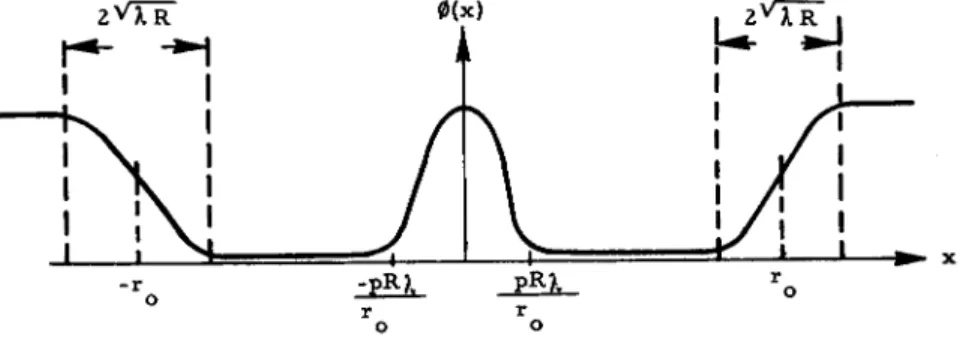
the circular obstacle may be summarized roughly as in Figure 17, amplitude vs distance off the axis.
Fig. 17. Diffraction Amplitude Behind Circular Obstacle.
(Ρ - 0.6)
CONCLUSION
Thus, so long as (RA/rQ) and (JTSO < < r , the shadow of a circular obstacle is pretty much like its geometrical shadow.
The latter condition is the more limiting on the range, and corresponds to about the same limitation as for square targets, for which one can see from Figures 1 through 5:
J2a2/RA = 8
for a decently precise shadow. This means that, for v i s i b l e light of 0.6μ wavelength, a 1-square-meter target, either a square or circle, casts a f a i r l y precise shadow for about 25 nautical miles.
REFERENCES
1. Slater, J. C , and Ν. H. Frank, Electromagnet ism. New York, McGraw-Hill Book Company, Inc., 1945, p. 185.
2. Born, M., and E. Wolf, Principles of Optics, New York,
APPENDIX We choose y = 0, since the pattern is symmetric. Huygens-Kirchhoff formula yields for th circular aperture: where d ξdη is an element of area of the circular aperture. Introducing polar coordinates (ξ = r cos θ, η = r sin 0) and expanding the square root 2 r 27T ç r Vr(x > = ' 1Α/Λλ β2π1/λ(Λ + X 11 j d& ° Γ dr e?Ti/RXr " 6 + Let u = r - χ cos θ, θ = θ : 27T
/r0««R\
\x « \Ζίΐ λ /
.·. Vr(x) = . iA/R7, e27ri^(R+^/2R)j άθ2
R
r - χ cos θ ο. Λ 2 2 2 / j / . n\ 7Ti^R(u - χ cos θ) / du (u + χ cos θ) ej
-X cos θ= un/ 2/AR
f
27r 3 tr(x) = - iA/RX e27Ti/A(R + χ2/2Κ) / d0 e"771 "2 COs2 θ/λ * p Jo AR/2 + V 2/AR (r - x cos θ) ο - ο • 2/ο dw w emW ' + xn/AR72 cos θ(r_ - x cos θ) n/ 2/AR 7Tiw2/2 s/2/AR χ cos θ g to χ < < n^AR. << rQ, since J dw e mw /2
J
dw e' χ cosQ si 2/ AR < 4, we may neglect this second e it is multiplied by x/v/ AR as compared with the first integral. ^2π aptrOO = - iA/RAe
27riR/XJ
d0 AR/2tt1 7ii/AR(r - 2r χ cos Θ) - e ο ο - 1 = - A e 27TiR/A 2 e7iir0 /RA j (2m x/RW _ ! Ο οSIXTH SYMPOSIUM ON BALLISTIC MISSILE AND AEROSPACE TECHNOLOGY
±27liZ cos θ
άθ e" cos (2πΖ cos θ) άθ = 2ttJq (27ΤΖ)
^ο
(See, for instance, Reference ( 3 ) , page 21, formula ( 9 ) , with η = 0.)
Now, for the circular obstacle, Babinetfs theorem gives:
»aptr( 27Ti/A(R + r0 2/ 2 R )
= A e J (27rr x / A R ) ο ο
* o b t c l( x ) = A2 Jo 2 (2 7 r rox / A R ) (See Figure 18), so
W l
( x ) < 0.16A*provided
2m x / A R < 1.7, x < 0.3AR/r ο ο
We note that in this region, where 12
* o b t c l( x ) - 0.16A2, X/V/XR" ί 0 . 3Ν Γ ^ / Γ < < 1 as it should be in order for the approximations used above to be v a l i d .
Diffraction Intensity Near Center of Circular Obstacle.
SIXTH SYMPOSIUM ON BALLISTIC MISSILE AND AEROSPACE TECHNOLOGY