Materials Characterization 171 (2021) 110807
Available online 3 December 2020
1044-5803/© 2020 The Author(s). Published by Elsevier Inc. This is an open access article under the CC BY license (http://creativecommons.org/licenses/by/4.0/).
Microstructure evolution in a nanocrystalline CoCrFeNi multi-principal element alloy during annealing
Pham Tran Hung
a, Megumi Kawasaki
b, Jae-Kyung Han
b, J ´ anos L. L ´ ab ´ ar
a,c, Jen o Gubicza ˝
a,*aDepartment of Materials Physics, E¨otv¨os Lor´and University, Budapest, P.O.B. 32, H-1518, Hungary
bSchool of Mechanical, Industrial and Manufacturing Engineering, Oregon State University, Corvallis, OR 97331, USA
cInstitute for Technical Physics and Materials Science, Centre for Energy Research, Budapest, Hungary
A R T I C L E I N F O Keywords:
Multi-principal element alloy Severe plastic deformation Microstructure
Thermal stability Recovery Hardness
A B S T R A C T
Experiments were conducted for the study of the evolution of the microstructure in a nanocrystalline CoCrFeNi multi-principal element alloy during annealing. The nanocrystalline state was achieved by high-pressure torsion (HPT) which is a well-defined severe plastic deformation technique. The heat treatment of the nanocrystalline CoCrFeNi alloy was performed in a differential scanning calorimeter (DSC). It was found that the thermogram contains two exothermic peaks with maxima at about 680 and 870 K. For further analysis, a different set of the samples were annealed to temperatures below and above the two DSC peaks. It was revealed the first exothermic peak was related to the decrease of the density of lattice defects (dislocations and twin faults) while the grain size remained consistent. The comparison of the measured and the calculated released heat values suggested that during this recovery a high concentration of excess vacancies was annihilated (about 10−3). The second exothermic peak corresponded to the recrystallization of the microstructure when the grain size increased from about 60 nm to about 660 nm. It was revealed that the hardness of the nanocrystalline CoCrFeNi alloy remained unchanged during recovery (first DSC peak) while recrystallization (second DSC peak) caused a decrease of the hardness from about 5100 MPa to about 3200 MPa.
1. Introduction
Multi-principal element alloys (MPEAs) or complex concentrated alloys (CCA), including high-entropy alloys (HEAs), are designed with multiple principal elements of equal or near equal molar ratios [1,2].
This is in contrast with conventional alloys involving one principal element with a minor amount of additional constituents. As a result, MPEAs offer an increased variety of elemental combinations. Further- more, these advanced materials exhibit improved properties, such as high strength at room and elevated temperatures [3–5], high fatigue and wear resistance [6,7], superior corrosion resistance [8], etc. One of the core effects [9] that differs MPEAs from conventional alloys is the high- entropy effect, which contributes to phase stabilization in solid solution MPEAs [10]. However, in order to achieve a high-entropy configuration, the materials would ideally maintain a single-phase solid solution state, which is not always present in MPEAs. For instance, CoCrFeMnNi be- comes unstable after prolonged exposure to intermediate temperature [11], and severely deformed HfNbTiZr decomposes into multiple phases after annealing [12]. Both theoretical and experimental studies [13–16]
reported that CoCrFeNi alloy remained a single phase state even if the equi-molar fraction condition was not fulfilled (with atomic composi- tions varying between 20% and 40%) [14], and this observation sug- gests a good stability of the single phase state in the MPEA. Furthermore, the CoCrFeNi alloy possesses exceptional mechanical properties [16], which can be further improved by the addition of other minor elements [17–20].
Besides modifying the chemical composition, another way to tune the mechanical properties of MPEAs is tailoring of the microstructure.
From the Hall-Petch equation [21,22], it is known that the hardness of a metallic material increases with decreasing grain size. In order to ach- ieve smaller grain size, severe plastic deformation (SPD) is commonly used with great success [9,16,19,23]. For instance, nanocrystalline (NC) CoCrFeNi powder has been produced successfully by mechanical alloying and then consolidated by spark plasma sintering (SPS). How- ever, annealing of this material resulted in the formation of chromium- carbide precipitates due to carbon contamination introduced by the milling process [24,25]. High-pressure torsion (HPT) is an SPD method capable of producing bulk nanocrystalline HEAs without contamination,
* Corresponding author.
E-mail address: jeno.gubicza@ttk.elte.hu (J. Gubicza).
Contents lists available at ScienceDirect
Materials Characterization
journal homepage: www.elsevier.com/locate/matchar
https://doi.org/10.1016/j.matchar.2020.110807
Received 24 October 2020; Received in revised form 30 November 2020; Accepted 30 November 2020
and has been successfully applied on different HEAs [12,19,20]. For a CoCrFeNi MPEA, HPT resulted in the formation of nanocrystalline grains through a reduction in grain size by three orders of magnitude and a hardness increase from ~1400 MPa to ~5100 MPa [16]. The high level of hardening is mainly caused by the high density of lattice defects, such as twin faults. The average twin fault spacing was about 7 nm in the CoCrFeNi MPEA after 10 turns of HPT.
Nanocrystalline materials, while these generally have outstanding strength, often have limited ductility as a major drawback [26–28]. Post deformation annealing for these materials usually offers a better balance in mechanical properties, by a decrease in strength and an increase in ductility. However, the softening of nanocrystalline MPEAs can be less significant than conventional metals, as many reports showed slower grain growth in MPEAs [29]. This effect is often explained as a contri- bution of the sluggish diffusion kinetics, one of the core effects of MPEAs [9]. At the same time, annealing-induced decomposition of MPEAs at intermediate temperatures (between 400 and 800 ◦C) may be facilitated by the small grain size since grain boundaries are the preferable sites for nucleation of new phases. The decomposition of MPEAs has already been observed in former publications [11,30–32]. For instance, annealing of CoCrFeMnNi HEA at 450 ◦C resulted in the formation of NiMn- and Co-rich phases even after 5 min [31]. Further increase of annealing time to 15 h introduced an additional FeCo-rich phase. If the temperature increased above 800 ◦C, a homogeneous solid solution phase state was achieved again due to the high entropy effect. The decomposition of CoCrFeMnNi HEA yielded hardening [31] where, for 100 h of annealing at 450 ◦C, a relative hardness increase reached about 70%.
The effect of heat treatment on the microstructure and mechanical behavior of MPEAs has been extensively studied since the recovery of the microstructure and the decomposition of the solid solution phase can significantly influence the strength and ductility of these materials. For example, He et al. using CALPHAD method calculated that CoCrFeNi has a stable single phase state at room temperature (RT), even when the atomic concentrations of Co, Fe and Ni were varied between 20% and 40% [14]; however, another study demonstrated that at elevated tem- peratures and long annealing times, even though CoCrFeNi alloy has a single phase state, a small addition of Al made the material unstable and precipitates were formed [33]. For CoCrFeMnNi HEA, three different phases precipitated after 500 days of annealing at 500 ◦C [32]; however, if processed by HPT before annealing, after heat treatment at 450 ◦C for 15 h, three different precipitates were observed and two of them appeared even after 5 min of annealing [31]. Bloomfield et al. reported that increasing Co content stabilized the single phase state of CoxCr- FeMnNi MPEA [34]; on the other hand, Mn had the opposite effect, and CoCrFeMnxNi with low Mn ratio showed contamination-related pre- cipitates at elevated temperatures [35]. Although, the phase stability in MPEAs was extensively investigated, the evolution of the lattice defects (e.g., dislocations and twin faults) in nanocrystalline MPEAs during annealing was only rarely studied (see e.g., [12]).
In this paper, an investigation is conducted for revealing the thermal stability of nanostructure in a CoCrFeNi MPEA. A sample processed by 10 turns of HPT was annealed by means of DSC and the characteristic temperatures of the microstructure evolution were determined from the thermogram. Then, specimens were heated up to specific temperatures and the changes of the lattice defect density and the grain size were determined. The influence of the microstructure evolution on hardness is also investigated and discussed in detail. To the knowledge of the authors, this is the first DSC study revealing the thermal stability of CoCrFeNi MPEA processed by HPT. In the literature, annealing of CoCrFeNi alloy has been studied without detecting the released heat, therefore the stored energy, and its correlation with the detailed microstructural and hardness evolution. In practice, simultaneous study of the lattice defect density during annealing is shown for the first time in this report. This investigation also describes the correlations of the defect evolutions with the heat released during annealing of CoCrFeNi
MPEA.
2. Material and methods 2.1. Processing of the material
Vacuum induction melting and drop casting of a mixture of four pure components (purity >99.9 wt%) was used for synthesizing Co25Cr25-
Fe25Ni25 MPEA. The initial cast ingot of ~39 mm in thickness was hot- rolled to a thickness of ~14 mm at 1050 ◦C, followed by a homogeni- zation heat treatment at 1100 ◦C for 1 h. The cast material was machined into cylindrical billets with a diameter of 10 mm, and these billets were sliced by electric discharge machining (EDM) into disks with a final thickness of ~0.85 mm. A conventional HPT facility with quasi- constrained set-up was utilized for the HPT process [36]. HPT process- ing was conducted for 10 turns at room temperature under a pressure of 6.0 GPa at a rotational speed of 1 rpm.
2.2. Differential scanning calorimetry
The thermal stability of the CoCrFeNi MPEA was studied at the edge of the disk sample processed by HPT for 10 turns. The HPT-processed disk was cut using a diamond saw into small specimens with about 1 mm width. The edge part of the HPT disk where the torsional strain is the higest was used for the characterization; hence the examination was conducted between the radii of 4 and 5 mm having accumulated equivalent strains of 200–250. The annealing process was carried out in a differential scanning calorimetry (DSC) by using a Perkin Elmer (DSC2) calorimeter. First, the characteristic temperatures of the micro- structure evolution were identified from the thermogram obtained by heating up a specimen up to the maximum testing temperature of 1000 K under an Ar atmosphere at a heating rate of 40 K/min. Afterward, these temperatures were set as target temperatures, and are reached by heating individual samples at a rate of 40 K/min. Then, to inspect the microstructure of these samples, they were quenched to room temper- ature at a cooling rate of about 300 K/min.
2.3. Microstructure study by electron microscopy
Transmission electron microscopy (TEM) was utilized to characterize the microstructures of the HPT-processed as well as the annealed sam- ples. A focused ion beam (FIB) technique with Ga+ions was used for cutting thin TEM-lamellae from the edge of the disk processed by 10 turns of HPT. First, a trench around the lamella was dug using 30 keV and 30 nA until a lamella thickness of about 4 μm was obtained. Then, a thinning process was performed at a voltage of 30 keV and a current of 7 nA until a lamella thickness of 1.5 μm was achieved. Finally, the lamella was cut and transferred to a grid, where it was further thinned at 16 keV and 50 pA, followed by polishing at 5 keV and 48 pA, and finished at 2 keV and 27 pA to remove a damaged layer.
TEM and energy-disperse X-ray spectroscopy (EDS) examinations were conducted using a Titan Themis G2 200 scanning transmission electron microscope (STEM). A four-segment Super-X EDS detector was equipped with the microscope. The spherical aberration was corrected at the imaging part, but probe-correction was not applied. The image resolution in STEM Z-contrast image mode was 0.16 nm, and these images were recorded using a Fishione high-angle annular dark-field (HAADF) detector. Together with the HAADF signal, the EDS data were measured in spectrum-image mode.
2.4. Microstructure characterization by X-ray diffraction
The microstructure of the CoCrFeNi samples was investigated by X- ray line profile analysis (XLPA). The surfaces of the HPT-processed and the annealed specimens were treated by mechanical polishing and a subsequent electropolishing. The mechanical polishing was started with
1200, 2500 and 4000 grit SiC abrasive papers, and continued with a colloidal alumina suspension with a particle size of 1 μm. Then, me- chanical polishing was finished using a colloidal silica suspension (OP-S) with a particle size of 40 nm. The surface preparation was completed with electropolishing at 25 V and 1 A. The composition of the electrolyte was 70% ethanol, 20% glycerine and 10% perchloric acid (in vol%).
The X-ray line profile measurements were performed by a diffrac- tometer using monochromatic CoKα1 radiation (wavelength: 0.1789 nm) and a single crystal Ge monochromator. The X-ray diffraction pat- terns were evaluated for the microstructure using the Convolutional Multiple Whole Profile (CMWP) fitting method [37]. In this procedure, all the peaks in the measured diffraction pattern are fitted simulta- neously with theoretically calculated profiles, and each theoretical reflection is obtained as the convolution of peaks related to the diffraction domain size, dislocations and twin faults. The anisotropic strain broadening of the diffraction profiles caused by dislocations was handled using the dislocation contrast factors [37]. For CoCrFeNi MPEA with an face centered cubic (fcc) structure, the dislocation contrast factors depend on parameters Ch00 and q. The former quantity has the values of 0.32 for both edge and screw dislocations while the theoretical values of q for edge and screw dislocations are 1.72 and 2.49, respec- tively, for CoCrFeNi MPEA as determined in a former study [16]. The CMWP method gives the area-weighted mean diffraction domain size (<x>), the dislocation density (ρ), the parameter describing the edge/
screw character of dislocations (q) and the twin-fault probability (β).
2.5. Hardness test
Hardness of the HPT-processed and the annealed samples was inspected using a Zwick Roell ZHμ indenter with an applied load of 500 g and 10 s dwell time. A surface treatment similar to that applied for XRD investigation (see section 2.4) was carried out before hardness testing. Each sample was indented 10 times, and then the estimated hardness values were averaged to achieve the final mean microhardness.
3. Results
3.1. DSC scan on the CoCrFeNi sample processed by HPT
The DSC curve measured at a heating rate of 40 K/min for the CoCrFeNi MPEA processed by HPT is shown in Fig. 1. Two distinct exothermic peaks can be seen in the thermogram. The first peak starts at
~620 K and reaches a maximum at ~680 K. At ~750 K, the first peak ends and a second peak begins. The second peak has its maximum at
~870 K and ends at ~920 K. These peaks are probably related to the recovery and/or recrystallization of HPT-processed nanocrystalline microstructure since phase transformation was not observed in the studied temperature range (discussed later). The integrations of the separate peak areas yield the values of 4.4 J/g for the first peak and 6.5 J/g for the second peak.
3.2. Microstructure evolution during annealing
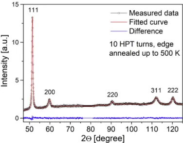
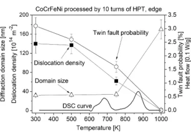
The evolution of the microstructure during annealing was studied for the HPT-processed CoCrFeNi MPEA by XLPA and TEM. The XRD pattern of the sample annealed to 500 K, which is typical for all samples, can be seen in Fig. 2. The diffractogram reveals that the CoCrFeNi alloy maintains a single fcc phase throughout the heat treatment process. The XRD patterns were fitted using the CMWP method to quantitatively characterize the diffraction domain size, the dislocation density and the twin fault probability of the HPT-processed sample and the annealed specimens. The results obtained from the CMWP evaluation are shown in Table 1, and also are plotted along with the DSC curve in Fig. 3 to display the correlation between the evolution of the microstructure during annealing and the exothermic signal. Fig. 4 shows the bright and dark field (BF and DF) images of the HPT-processed samples (a)-(c) before annealing and after annealing towards (d)-(e) 500 K, (f)-(g) 750 K and (h) 1000 K. The average grain size was determined directly from the several TEM images and is shown in Table 1, as well as plotted with the DSC curve in Fig. 5 to compare the evolution of grain sizes during annealing to the appearance of the exothermic peaks.
Immediately after HPT-processing, the grain size was about 60 nm and the CoCrFeNi MPEA contained a very high defect density as seen in Fig. 4a–b, namely the dislocation density was 140 ×1014 m−2 while the twin fault probability was about 3% as determined by XLPA. The latter value corresponds to an average twin fault spacing of about 7 nm calculated as 100d111/β where d111 is the spacing between the {111}
planes [38]. The presence of nanotwins in the HPT-processed sample is confirmed by the TEM image in Fig. 4c. The diffraction domain size of
~32 nm was about half of the grain size obtained by TEM. The difference can be explained by the hierarchical microstructure of the HPT- processed material. In practice, grain subdivision into subgrains is a general observation for SPD-processed metals and alloys [39]. Since
Fig. 1.DSC thermogram obtained for the sample cut from the edge of a disk processed by 10 turns of HPT.
Fig. 2.CMWP fitting for the diffractogram taken on the HPT-processed sample heated up to 500 K. The black open circles and the red solid line show the measured and the fitted patterns, respectively. The difference between them is shown by the blue line at the bottom of the figure. (For interpretation of the references to colour in this figure legend, the reader is referred to the web version of this article.)
XRD is sensitive to small crystallographic misorientations, the diffrac- tion domain size characterizes the subgrain size rather than the grain size [38]. The heat treatment up to 500 K did not yield any significant exothermic or endothermic DSC signal which is in accordance with the practically unchanged microstructure as seen in Table 1 as well as Figs. 3 and 5.
The first exothermic DSC peak finished at 750 K, therefore the microstructure was studied at this temperature. Fig. 3 reveals that after annealing up to 750 K both the dislocation density and the twin fault probability were reduced to about half of the values measured imme- diately after HPT as also seen in Table 1, while there were no noticeable changes in the average diffraction domain and grain sizes as described in Figs. 3 and 5, respectively.
The microstructure development during the second exothermic DSC peak can be described by comparing the XLPA and TEM results obtained for 750 and 1000 K. Between these two temperatures, the average grain Table 1
Microstructure parameters obtained after heating up to different temperatures in DSC. The mean diffraction domain size (<x>), the dislocation density (ρ), the parameter describing the edge/screw character of dislocations (q) and the twin- fault probability (β) were determined by XLPA while the grain size (d) was ob- tained from TEM.
Temperature
[K] d [nm] <x >
[nm] ρ [1014
m−2] q β [%]
300 59 ±3 32 ±3 140 ±20 2.2 ±
0.1 3.1 ±
500 60 ±3 33 ±4 137 ±18 2.4 ± 0.3
0.1 2.6 ±
750 57 ±3 34 ±5 62 ±8 2.3 ± 0.2
0.1 1.6 ±
1000 660 ±20 170 ±20 0.8 ±0.1 1.7 ± 0.2
0.1 0 ±0.1
Fig. 3. The diffraction domain size, the dislocation density and the twin-fault probability obtained by XLPA as well as the heat flow measured by DSC as a function of the annealing temperature.
Fig. 4. BF (a,c,d,f,h) and DF (b,e,g) TEM images obtained on the HPT-processed specimen and the samples annealed up to different temperature in DSC. The temperature of heat treatment can be seen on the images. The white arrows in (c) indicate twin faults.
Fig. 5.The grain size determined by TEM and the heat flow measured by DSC as a function of the annealing temperature.
size and the diffraction domain size increased drastically, while dislo- cation density and twin fault probability diminished to very small values as visualized in Figs. 3 and 5. Namely, the average grain size increased by over an order of magnitude, from about 60 nm to ~660 nm as shown in Fig. 4a–h, while the diffraction domain size also increased five folds, from ~34 nm to ~170 nm. In addition, the dislocation density decreased to ~0.8 × 10¹⁴ m−2 and the twin fault probability fell under the detection limit of XLPA method (~0.1%). The latter observation is not in contradiction to the appearance of twins in the TEM image of Fig. 4h.
The average twin spacing in the BF image is about 200 nm which cor- responds to the lower detection limit of twin fault probability in XLPA.
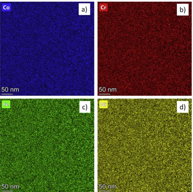
The elemental distributions of all the four constituents in the present CoCrFeNi MPEA were homogeneous immediately after HPT as shown in Fig. 6, and it remained unchanged during annealing up to 1000 K.
Therefore, development of chemical heterogeneities, segregation or phase decomposition were not observed in the studied material.
3.3. Change of the hardness during annealing
Fig. 7 shows the change of the hardness value versus annealing temperature, as well as its correlation to the exothermic peaks for the HPT-processed CoCrFeNi MPEA sample. The hardness after HPT was
Fig. 6.EDS elemental maps for Co (a), Cr (b), Fe (c) and Ni (d) obtained for the HPT-processed sample by TEM.
Fig. 7. The hardness and the heat flow measured by DSC as a function of the annealing temperature.
about 5100 MPa and it did not change significantly up to 750 K, i.e., the structural changes related to the first DSC peak did not yield softening.
On the other hand, the heat treatment between 750 and 1000 K led to a considerable reduction in hardness from >5000 to ~3200 MPa, i.e., the material softened during the second exothermic peak.
4. Discussion
The present study revealed an excellent phase stability of the CoCr- FeNi MPEA processed by HPT since neither decomposition nor forma- tion of chemical heterogeneities was observed. Thus, the stability of the CoCrFeNi MPEA is better than the most frequently studied CoCrFeMnNi HEA. Indeed, former studies have shown that compositional in- homogeneities were developed in CoCrFeMnNi alloy immediately after processing by casting without any annealing [16,40]. Namely, the interdendritic regions were enriched in Mn and Ni since these elements have the lowest melting points in pure form (1519 and 1726 K, respectively). Moreover, two-component Mn–Ni alloy with equal molar fractions solidifies at even lower temperatures of about 1300 K. There- fore, during cooling the firstly crystallized regions are enriched in Cr, Fe and Co since these elements have relatively high melting points (be- tween 1768 and 2180 K), while the interdendritic volumes are solidified later during cooling. Chemical heterogeneities in CoCrFeMnNi HEA were observed even if an additional rolling and a subsequent homoge- nization heat treatment were applied after casting [40]. It seems that the absent of Mn with a relatively low melting point significantly improved the homogeneity of CoCrFeNi even after heating up to 1000 K. It is worth noting that the addition of other elements to CoCrFeMnNi HEA may even result in a multiple phase microstructure. For instance, in Al0.5CoCrFeMnNi HEA a Ni-rich fcc phase and an Al-rich B2 phase were developed in the initial material before HPT [41]. Annealing after HPT- processing at 800 ◦C for 1 h resulted in the formation of an additional (Fe,Cr) rich σ-phase which significantly improved the hardness of the material. Nevertheless, the HPT-processed CoCrFeNi MPEA studied in this paper maintained a single phase without formation of such annealing-induced σ-phase.
The results of the present microstructure investigations evidently proved that the first exothermic DSC peak corresponds to recovery in the HPT-processed CoCrFeNi MPEA, as only reduction of the lattice defect density without any change in grain size occurred as shown in Figs. 3–5.
During the second exothermic peak, recrystallization was also observed.
This separate processes of recovery and recrystallization during DSC annealing has also been observed for conventional nanocrystalline metallic alloys processed by HPT at room temperature [42,43]. For conventional alloys, the reason of the clearly separated structural evo- lution during annealing is attributed to the stronger retarding effect of solute atoms and secondary phase particles on recrystallization (e.g., on the movement of grain boundaries) than on recovery (i.e., on the annihilation of dislocations and vacancies). In the case of solid solutions, the segregation of solute atoms to grain boundaries can also contribute to the stabilization of the as-processed grain structure. If the alloying element concentration was not very high or HPT-processed ultrafine- grained (UFG) pure fcc metals were studied by DSC, only a single exothermic peak was observed, and this peak appeared at the homolo- gous temperature of about 0.33–0.36 [39,42,43]. This single peak cor- responded to a simultaneous occurrence of recovery and recrystallization [39,42]. For HPT-processed UFG and nanocrystalline fcc alloys with considerable solute concentrations (e.g., for Ni – 5 at.%
Mo), two DSC peaks were observed at the homologous temperatures of about 0.4–0.45 and 0.55–0.60 [42,43]. For the present nanocrystalline CoCrFeNi MPEA, the first and second peaks appeared at the homologous temperatures of ~0.4 and ~ 0.5, respectively. Therefore, the stability of the nanocrystalline microstructure of the CoCrFeNi MPEA processed by HPT are reasonable consistent with the conventional alloys deformed plastically in a similar way. It is worth noting that the value of the stacking fault energy (SFE) also influences the occurrence of
recrystallization [18]. Namely, for low SFE metallic materials recrys- tallization is promoted by the easy formation of low energy twin boundaries. The present study suggests that although the SFE of CoCr- FeNi MPEA is relatively low (20 mJ/m2), the homologous temperature of recrystallization is only slightly lower than that for traditional alloys with higher SFE, and in addition recovery precedes recrystallization in the DSC thermogram. The retarded recrystallization can be explained by the distorted MPEA lattice as discussed in the next paragraph.
The stability of the present HPT-processed fcc CoCrFeNi MPEA is worth to compare to that obtained for Ni since this is the only compo- nent in this alloy which has also fcc structure in pure form. For 99.99%
purity Ni processed by five turns of HPT at room temperature, a single exothermic DSC peak appeared at the homologous temperature of 0.33 and the released heat was 1.8 J/g [44]. This value is about six times smaller than the total heat released in the two DSC peaks for the present CoCrFeNi MPEA. The much higher released heat was caused by the six times higher dislocation density and the three times smaller grain size.
Since the melting points of Ni and CoCrFeNi are very close (about 1700 K), therefore the different defect density can not be attributed to the difference in the homologous temperature of HPT processing. Rather, the annihilation of defects in CoCrFeNi alloy was hindered by the higher resistance of the distorted MPEA lattice against the motion of disloca- tions and grain boundaries [45]. The much larger stored energy in the HPT-processed CoCrFeNi alloy gave a higher driving force for recovery and recrystallization compared to Ni. However, despite this fact the homologous temperatures of recovery and recrystallization were higher for CoCrFeNi MPEA than for pure Ni. This observation suggests that the retarding effect of the lattice on recovery and recrystallization in CoCrFeNi is higher than the promoting effect of the higher driving force.
It is worth to compare the measured heat released in the two DSC peaks and the change in the stored energy calculated from the micro- structural parameters obtained by XLPA and TEM. The stored energy per unit mass before and after the DSC peaks is considered as the sum of the lattice defect energies. The energy stored in grain boundaries (GBs) can be determined using the following equation [46]:
EGB=3γGB
dρm, (1)
where γGB is the GB energy per unit area, d is the average grain size determined by TEM and ρm is the mass density of CoCrFeNi (7.53 g/cm 3 [47]). For the first exothermic peak, the grain size remained reasonably consistent as shown in Table 1 and there was no remarkable contribu- tion of GBs to the released heat. During the second DSC peak, the grain size increased by more than one order of magnitude, and the corre- sponding change of the stored energy was 4.9 ±0.3 J/g as obtained by Eq. (1). In this calculation, the GB energy per unit area was taken as 0.77 J/m2 where the value is valid in the temperature range of the second exothermic peak at 800–900 K [48]. The estimated changes of the stored energies for different defects are listed in Table 2 and the detail calcu- lations are described in here.
The contribution of dislocations to the stored energy is given as [49]:
Edisl=AGb2ρ ρm
ln (
1 b ̅̅̅
√ρ )
, (2)
where G is the shear modulus (84 GPa for CoCrFeNi MPEA [50]), b is the magnitude of the Burgers vector (0.263 nm, derived from the lattice constant obtained in a former study [16]), ρ is the dislocation density, and A is a factor depending on the edge/screw character of dislocations.
For pure screw and edge dislocations, A equals (4π)−1 and (4π (1 - ν))−1, respectively, where ν is the Poisson’s ratio (0.25 for CoCrFeNi MPEA [51]). For a sample having dislocations with a mixed character, A can be obtained from parameter q determined by XLPA using the rule of mixtures:
A= q− qedge
qscrew− qedge
1 4π+
qscrew− q qscrew− qedge
1
4π(1− ν), (3)
where qedge and qscrew are the q parameters for pure edge and screw dislocations, respectively. For CoCrFeNi MPEA, qedge =1.72 and qscrew
= 2.49. The experimentally determined values of q for the different samples are listed in Table 1. Using Eqs. (2) and (3), the contributions of dislocations to the stored energy in the first and second exothermic peaks were obtained as 1.4 ±0.8 and 1.6 ±0.2 J/g, respectively.
For twin faults in fcc materials, the stored energy can be calculated using the following equation [52]:
Etwin= γtwinβ
d111ρm, (4)
where γtwin is the twin fault energy per unit area (taken as 10 mJ/m2, since for fcc materials the twin fault energy is about half of its SFE of about 20 mJ/m2 for CoCrFeNi [53]), β is the twin fault probability, and d111 is the spacing between the neighbouring {111} planes. For the first and second DSC peaks, the changes in twin fault energy are 0.06 ±0.02 and 0.10 ± 0.02 J/g, respectively. The sum of the changes in the different stored energy contributions is 1.46 ±1.32 J/g for the first DSC peak while it is 6.60 ±0.52 J/g for the second peak (see also Table 2).
The contribution of GB energy to the heat release is zero in the first DSC peak, but it has the major contribution to the second one. The changes in the energies stored in dislocations and twin faults are similar for the first and second exothermic peaks, while the twin faults energy plays an insignificant role in the total stored energy. The change of the total stored energy calculated from the evolution of lattice defects is in accordance with the measured heat released for the second exothermic peak. By contrast, there is a noticeable deficit in the case of the first exothermic peak, i.e., the calculated change in the stored energy is much less than the measured released heat. This difference can be explained by the annihilation of vacancies or vacancy clusters. Former studies have indicated that after SPD-processing, a very high vacancy concentration developed in the deformed materials [49,54]. Taking the assumption that the difference between the calculated and measured released heats is due to vacancy annihilation, the excess vacancy concentration (cv) in the HPT-processed CoCrFeNi MPEA is estimated as follows. The energy stored in vacancies (Evac) can be related to the vacancy concentration as [49]:
Evac=evaccv
NA
M, (5)
where evac is the vacancy formation energy (~1.7 eV for CoCrFeNi
[55,56]), NA is the Avogadro’s number (6 ×10²³ mol−1), and M is the molar mass of CoCrFeNi (56.37 g/mol). Hence, the change of the va- cancy concentration (∆cv) during the first DSC peak can be obtained from Eq. (5) with the assumption that the energy released by vacancy annihilation (∆Ev) corresponds to the difference between the measured released heat and the change of the sum of the stored energies of other defects. This calculation yields the change of the vacancy concentration in the first DSC peak of about (1.0 ±0.7) ×10−3, which is similar to the values obtained previously for conventional nanocrystalline metals and alloys where there is a summary of the excess vacancy concentrations for SPD-processed materials [39]. For instance, at the highly deformed re- gion in a 99.95% purity Cu disk after 10 turns by HPT at room tem- perature an excess vacancy concentration of ~2 ×10⁻³ was obtained and the majority of vacancies were agglomerated into clusters consisting of 7–9 vacancies [54]. For a Ni-0.3 at.% Mo processed by 20 turns of HPT at room temperature, the vacancy concentration was obtained in the range of 0.7–1.2 ×10⁻³ [57]. When the Mo content increased to 5 at.%
in Ni, HPT-processing for 20 turns led to a vacancy concentration of 1.6–2.1 ×10⁻³. Thus, it can be concluded that the concentration of excess vacancies formed in the HPT-processed CoCrFeNi HEA does not differ considerably from the values determined in conventional pure metals and alloys after HPT.
It is worth noting that for the heats released at the first and second exothermic peaks the main contributors were vacancies and grain boundaries, respectively. Namely, 67% of the released heat was related to vacancies and 32% was caused by the annihilation of dislocations at the first peak. In the case of the second DSC peak, 74% of the heat was released due to the decrease of the grain boundary area and 24% was related to dislocation annihilation.
The comparison of Figs. 3, 5 and 7 reveal that the hardness was not sensitive to the reduction of the density of defects (dislocations and twin faults) at the first DSC peak, and softening was observed only when the grain size increased significantly at the second exothermic peak. Similar results were obtained formerly for HPT-processed Ni – 5 wt% Mo alloy and 316 L stainless steel [58,59]. There may be two reasons behind this effect. The first one is that annealing can also yield a relaxation of the grain boundaries, therefore the emission of dislocations from the boundaries becomes more difficult [60]. This hardening effect can compensate the softening caused by the defect annihilation. The second reason may be that hardness testing results in an 8% plastic strain in the probed material, yielding local defect multiplication. The corresponding strain hardening in the annealed samples can increase the hardness back to a similar level as observed before the heat treatment. Thus, it can be concluded that the hardness of the nanocrystalline CoCrFeNi MPEA remained stable up to 750 K and considerable softening can be observed only at the second exothermic DSC peak.
5. Summary and conclusions
The thermal stability of the nanocrystalline microstructure in a HPT- processed CoCrFeNi MPEA was studied. The evolutions of the defect density and grain size were monitored by XLPA and TEM as a function of the annealing temperature. The following conclusions were drawn from the results:
1. Two exothermic DSC peaks were developed during heating up to 1000 K. In the temperature range corresponding to the first peak, only the lattice defect density decreased while the grain size remained about 60 nm. Indeed, the dislocation density decreased from ~140 × 1014 m−2 to ~60 × 1014 m−2 and the twin fault probability (~3%) was also reduced to about half. The maximum of this first exothermic peak was measured at the temperature of about 680 K. The second DSC peak has a maximum at ~870 K and this peak was related to recrystallization since the grain size increased by an order of magnitude to ~660 nm. The homologous temperatures of the two DSC peak maxima were ~ 0.4 and ~ 0.5 which are Table 2
Comparison of the change of the stored energies as calculated from the defect densities and the heat released during the two DSC peaks for the CoCrFeNi sample processed by HPT. ΔEdisl, ΔEtwin and ΔEGB are the changes of the energies stored in dislocations, twin faults and grain boundaries, respectively. H is the heat released in the exothermic DSC peak. ΔEvac is the change of the energy stored in vacancies as estimated from the difference between the sum of the calculated stored energies and the measured released heat, and Δcv is the change of vacancy concentration calculated from ΔEvac (see the text for more details).
Calculated change of stored energy
[J/g] Measured heat released [J/
g]
1st DSC peak ΔEGB =0 ±0.5 H =4.4 ±0.6 ΔEdisl =1.4 ±0.8
ΔEtwin =0.06 ±0.02 Sum =1.46 ±1.32 ΔEvac =2.94 ±1.92 Δcv [10−3] =1.0 ±0.7 2nd DSC
peak ΔEGB =4.9 ±0.3 H =6.5 ±0.7
ΔEdisl =1.6 ±0.2 ΔEtwin =0.10 ±0.02 Sum =6.60 ±0.52
reasonably consistent with the values obtained for conventional fcc alloys processed by HPT at room temperature.
2. For the second exothermic peak, the experimentally determined released heat was in good agreement with the change of the stored energy calculated from the evolutions of the defect densities and the grain size. At the same time, for the first DSC peak the measured released heat was about three times higher than the calculated stored energy. The difference can be explained by the annihilation of excess vacancies and vacancy clusters formed during HPT. From this dif- ference, the estimated vacancy concentration annihilated during the detection of the first DSC peak was ~10−3. This value is similar to the excess vacancy concentrations annihilated in other conventional nanocrystalline alloys.
3. The hardness was not sensitive to the recovery observed at the first DSC peak. By contrast, the hardness decreased from about 5100 MPa to ~3200 MPa when recrystallization occurred at the second exothermic peak. This result reveals that the hardness of the nano- crystalline CoCrFeNi alloy remains stable up to the temperature of 750 K which corresponds to the end of the first DSC peak.
Data availability
The raw/processed data required to reproduce these findings cannot be shared at this time due to technical or time limitations.
Declaration of Competing Interest
The authors declare that they have no conflict of interest.
Acknowledgement
This work was supported in part by the Ministry of Human Capacities of Hungary within the ELTE University Excellence program (1783-3/
2018/FEKUTSRAT); in part by the grant no. VEKOP-2.3.3-15-2016- 00002 of the European Structural and Investment Funds; and in part by the National Science Foundation of the United States under Grant No.
DMR-1810343. The preparation of the TEM lamellae by Levente Ill´es is also acknowledged.
References
[1] B. Cantor, I. Chang, P. Knight, A. Vincent, Microstructural development in equiatomic multicomponent alloys, Mater. Sci. Eng. A 375 (2004) 213–218.
[2] J.-W. Yeh, S.-K. Chen, S.-J. Lin, J.-Y. Gan, T.-S. Chin, T.-T. Shun, C.-H. Tsau, S.- Y. Chang, Nanostructured high-entropy alloys with multiple principal elements:
novel alloy design concepts and outcomes, Adv. Eng. Mater. 6 (2004) 299–303.
[3] Y. Zhou, Y. Zhang, Y. Wang, G. Chen, Solid solution alloys of AlCoCrFeNiTi x with excellent room-temperature mechanical properties, Appl. Phys. Lett. 90 (2007) 181904.
[4] X. Wang, Y. Zhang, Y. Qiao, G. Chen, Novel microstructure and properties of multicom- ponent CoCrCuFeNiTix alloys, Intermetallics 15 (2007) 357–362.
[5] O. Senkov, J. Scott, S. Senkova, F. Meisenkothen, D. Miracle, C. Woodward, Microstructure and elevated temperature properties of a refractory TaNbHfZrTi alloy, J. Mater. Sci. 47 (2012) 4062–4074.
[6] M.A. Hemphill, T. Yuan, G. Wang, J. Yeh, C. Tsai, A. Chuang, P. Liaw, Fatigue behavior of Al0. 5CoCrCuFeNi high entropy alloys, Acta Mater. 60 (2012) 5723–5734.
[7] M.-H. Chuang, M.-H. Tsai, W.-R. Wang, S.-J. Lin, J.-W. Yeh, Microstructure and wear behavior of AlxCo1. 5CrFeNi1. 5Tiy high-entropy alloys, Acta Mater. 59 (2011) 6308–6317.
[8] Y. Chen, T. Duval, U. Hung, J. Yeh, H. Shih, Microstructure and electrochemical properties of high entropy alloys—a comparison with type-304 stainless steel, Corros. Sci. 47 (2005) 2257–2279.
[9] Y. Jien-Wei, Recent progress in high entropy alloys, Ann. Chim. Sci. Mater. 31 (2006) 633–648.
[10] C.-Y. Cheng, Y.-C. Yang, Y.-Z. Zhong, Y.-Y. Chen, T. Hsu, J.-W. Yeh, Physical metallurgy of concentrated solid solutions from low-entropy to high-entropy alloys, Curr. Opinion Solid State Mater. Sci. 21 (2017) 299–311.
[11] E. Pickering, R. Munoz-Moreno, H.J. Stone, N.G. Jones, Precipitation in the ˜ equiatomic high-entropy alloy CrMnFeCoNi, Scr. Mater. 113 (2016) 106–109.
[12] P.T. Hung, M. Kawasaki, J.-K. Han, J.L. L´ab´ar, J. Gubicza, Thermal stability of a nanocrystalline HfNbTiZr multi-principal element alloy processed by high-pressure torsion, Mater. Charact. 168 (2020) 110550.
[13] M. Vaidya, G.M. Muralikrishna, S. Divinski, B. Murty, Experimental assessment of the thermodynamic factor for diffusion in CoCrFeNi and CoCrFeMnNi high entropy alloys, Scr. Mater. 157 (2018) 81–85.
[14] F. He, Z. Wang, Q. Wu, S. Niu, J. Li, J. Wang, C. Liu, Solid solution island of the co- Cr- Fe-Ni high entropy alloy system, Scr. Mater. 131 (2017) 42–46.
[15] W. Huo, H. Zhou, F. Fang, X. Hu, Z. Xie, J. Jiang, Strain-rate effect upon the tensile behavior of CoCrFeNi high-entropy alloys, Mater. Sci. Eng. A 689 (2017) 366–369.
[16] J. Gubicza, P.T. Hung, M. Kawasaki, J.-K. Han, Y. Zhao, Y. Xue, J.L. L´ab´ar, Influence of severe plastic deformation on the microstructure and hardness of a CoCrFeNi high- entropy alloy: a comparison with CoCrFeNiMn, Mater. Charact.
154 (2019) 304–314.
[17] A. Verma, P. Tarate, A. Abhyankar, M. Mohape, D. Gowtam, V. Deshmukh, T. Shanmugasundaram, High temperature wear in CoCrFeNiCux high entropy alloys: the role of cu, Scr. Mater. 161 (2019) 28–31.
[18] G. Sathiaraj, M. Ahmed, P.P. Bhattacharjee, Microstructure and texture of heavily cold- rolled and annealed fcc equiatomic medium to high entropy alloys, J. Alloys Compd. 664 (2016) 109–119.
[19] Q. Tang, Y. Huang, Y. Huang, X. Liao, T. Langdon, P. Dai, Hardening of an Al0.
3CoCrFeNi high entropy alloy via high-pressure torsion and thermal annealing, Mater. Lett. 151 (2015) 126–129.
[20] A. Heczel, M. Kawasaki, J.L. L´ab´ar, J. Jang, T.G. Langdon, J. Gubicza, Defect structure and hardness in nanocrystalline CoCrFeMnNi high-entropy alloy processed by high- pressure torsion, J. Alloys Compd. 711 (2017) 143–154.
[21] E. Hall, The deformation and ageing of mild steel: III discussion of results, Proceed.
Phys. Soc. Sec. B 64 (1951) 747.
[22] A. Cracknell, N. Petch, Frictional forces on dislocation arrays at the lower yield point in iron, Acta Metall. 3 (1955) 186–189.
[23] M. Vaidya, G.M. Muralikrishna, B.S. Murty, High-entropy alloys by mechanical alloy- ing: a review, J. Mater. Res. 34 (2019) 664–686.
[24] S. Praveen, J. Basu, S. Kashyap, R.S. Kottada, Exceptional resistance to grain growth in nanocrystalline CoCrFeNi high entropy alloy at high homologous temperatures, J. Alloys Compd. 662 (2016) 361–367.
[25] M. Vaidya, A. Karati, A. Marshal, K. Pradeep, B. Murty, Phase evolution and stability of nanocrystalline CoCrFeNi and CoCrFeMnNi high entropy alloys, J. Alloys Compd. 770 (2019) 1004–1015.
[26] Y.-H. Zhao, X.-Z. Liao, S. Cheng, E. Ma, Y.T. Zhu, Simultaneously increasing the ductility and strength of nanostructured alloys, Adv. Mater. 18 (2006) 2280–2283.
[27] Y.M. Wang, E. Ma, Three strategies to achieve uniform tensile deformation in a nanostructured metal, Acta Mater. 52 (2004) 1699–1709.
[28] C. Koch, Optimization of strength and ductility in nanocrystalline and ultrafine grained metals, Scr. Mater. 49 (2003) 657–662.
[29] E. Pickering, N. Jones, High-entropy alloys: a critical assessment of their founding principles and future prospects, Int. Mater. Rev. 61 (2016) 183–202.
[30] B. Schuh, B. V¨olker, V. Maier-Kiener, J. Todt, J. Li, A. Hohenwarter, Phase decomposition of a single-phase AlTiVNb high-entropy alloy after severe plastic deformation and annealing, Adv. Eng. Mater. 19 (2017) 1600674.
[31] B. Schuh, F. Mendez-Martin, B. V¨olker, E.P. George, H. Clemens, R. Pippan, A. Hohenwarter, Mechanical properties, microstructure and thermal stability of a nanocrystalline CoCrFeMnNi high-entropy alloy after severe plastic deformation, Acta Mater. 96 (2015) 258–268.
[32] F. Otto, A. Dlouhý, K.G. Pradeep, M. Kubˇenov´a, D. Raabe, G. Eggeler, E.P. George, Decomposition of the single-phase high-entropy alloy CrMnFeCoNi after prolonged anneals at intermediate temperatures, Acta Mater. 112 (2016) 40–52.
[33] F. He, Z. Wang, Q. Wu, J. Li, J. Wang, C. Liu, Phase separation of metastable CoCrFeNi high entropy alloy at intermediate temperatures, Scr. Mater. 126 (2017) 15–19.
[34] M.E. Bloomfield, K.A. Christofidou, N.G. Jones, Effect of co on the phase stability of CrMnFeCoxNi high entropy alloys following long-duration exposures at intermediate temperatures, Intermetallics 114 (2019) 106582.
[35] K. Christofidou, E. Pickering, P. Orsatti, P. Mignanelli, T. Slater, H. Stone, N. Jones, On the influence of Mn on the phase stability of the CrMnxFeCoNi high entropy alloys, Intermetallics 92 (2018) 84–92.
[36] R.B. Figueiredo, P.R. Cetlin, T.G. Langdon, Using finite element modeling to examine the flow processes in quasi-constrained high-pressure torsion, Mater. Sci.
Eng. A 528 (2011) 8198–8204.
[37] G. Rib´arik, J. Gubicza, T. Ung´ar, Correlation between strength and microstructure of ball- milled Al–mg alloys determined by X-ray diffraction, Mater. Sci. Eng. A 387 (2004) 343–347.
[38] J. Gubicza, X-Ray Line Profile Analysis in Materials Science, IGI Global, Hershey, USA, 2014.
[39] J. Gubicza, Defect Structure and Properties of Nanomaterials, Woodhead Publishing, Duxford, UK, 2017.
[40] M.N. Hasan, J. Gu, S. Jiang, H.J. Wang, M. Cabral, S. Ni, X.H. An, M. Song, L.
M. Shen, X.Z. Liao, Effects of elemental segregation on microstructural evolution and local mechanical properties in a dynamically deformed CrMnFeCoNi high entropy alloy, Scr. Mater. 190 (2021) 80–85.
[41] T.S. Reddy, I.S. Wani, T. Bhattacharjee, S.R. Reddy, R. Saha, P.P. Bhattacharjee, Severe plastic deformation driven nanostructure and phase evolution in a Al0.5CoCrFeMnNi dual phase high entropy alloy, Intermetallics 91 (2017) 150–157.
[42] G. Kapoor, Y. Huang, V.S. Sarma, T.G. Langdon, J. Gubicza, Evolution of the microstructure during annealing of ultrafine-grained Ni with different Mo contents, Mater. Charact. 130 (2017) 56–63.
[43] P. Jenei, J. Gubicza, E. Yoon, H. Kim, J. L´ab´ar, High temperature thermal stability of pure copper and copper–carbon nanotube composites consolidated by high pressure torsion, Compos. A: Appl. Sci. Manuf. 51 (2013) 71–79.
[44] A.P. Zhilyaev, G.V. Nurislamova, S. Surinach, M.D. Baro, T.G. Langdon, Calorimetric measurements of grain growth in ultrafine-grained nickel, Mater.
Phys. Mech. 5 (2002) 23–30.
[45] G. Dirras, J. Gubicza, A. Heczel, L. Lilensten, J.-P. Couzini´e, L. Perri`ere, Y. Guillot, A. Hocini, Microstructural investigation of plastically deformed
Ti20Zr20Hf20Nb20Ta20 high entropy alloy by X-ray diffraction and transmission electron microscopy, Mater. Char. 108 (2015) 1–7.
[46] F.J. Humphreys, M. Hatherly, Recrystallization and Related Annealing Phenomena, Elsevier, 2012.
[47] R.B. Mane, B.B. Panigrahi, Sintering mechanisms of mechanically alloyed CoCrFeNi high-entropy alloy powders, J. Mater. Res. 33 (2018) 3321–3329.
[48] M. Vaidya, K. Pradeep, B. Murty, G. Wilde, S. Divinski, Radioactive isotopes reveal a non sluggish kinetics of grain boundary diffusion in high entropy alloys, Sci. Rep.
7 (2017) 1–11.
[49] E. Schafler, G. Steiner, E. Korznikova, M. Kerber, M. Zehetbauer, Lattice defect investigation of ECAP-Cu by means of X-ray line profile analysis, calorimetry and electrical resistometry, Mater. Sci. Eng. A 410 (2005) 169–173.
[50] Z. Wu, H. Bei, G.M. Pharr, E.P. George, Temperature dependence of the mechanical properties of equiatomic solid solution alloys with face-centered cubic crystal structures, Acta Mater. 81 (2014) 428–441.
[51] G. Laplanche, P. Gadaud, C. B¨arsch, K. Demtr¨oder, C. Reinhart, J. Schreuer, E.
P. George, Elastic moduli and thermal expansion coefficients of medium-entropy subsystems of the CrMnFeCoNi high-entropy alloy, J. Alloys Compd. 746 (2018) 244–255.
[52] Z. Heged˝us, J. Gubicza, M. Kawasaki, N.Q. Chinh, K. Süvegh, Z. Fogarassy, T.
G. Langdon, High temperature thermal stability of ultrafine-grained silver processed by equal- channel angular pressing, J. Mater. Sci. 48 (2013) 1675–1684.
[53] A. Zaddach, C. Niu, C. Koch, D. Irving, Mechanical properties and stacking fault energies of nifecrcomn high-entropy alloy, JOM 65 (2013) 1780–1789.
[54] J. Cíˇˇzek, M. Janeˇcek, O. Srba, R. Kuˇzel, Z. Barnovsk´a, I. Proch´azka, S. Dobatkin, Evolution of defects in copper deformed by high-pressure torsion, Acta Mater. 59 (2011) 2322–2329.
[55] W. Chen, X. Ding, Y. Feng, X. Liu, K. Liu, Z. Lu, D. Li, Y. Li, C. Liu, X.-Q. Chen, Vacancy formation enthalpies of high-entropy FeCoCrNi alloy via first-principles calculations and possible implications to its superior radiation tolerance, J. Mater.
Sci. Technol. 34 (2018) 355–364.
[56] K. Sugita, N. Matsuoka, M. Mizuno, H. Araki, Vacancy formation enthalpy in CoCrFeMnNi high-entropy alloy, Scr. Mater. 176 (2020) 32–35.
[57] G. Kapoor, L. P´eter, E. Fekete, J.L. L´ ´ab´ar, J. Gubicza, Stored energy in nanocrystalline Ni-Mo films processed by electrodeposition, J. Alloys Compd. 796 (2019) 307–313.
[58] G. Kapoor, Y. Huang, V. Subramanya Sarma, T.G. Langdon, J. Gubicza, Influence of Mo alloying on the thermal stability and hardness of ultrafine-grained Ni processed by high-pressure torsion, J. Mater. Res. Techn. 6 (2017) 361–368.
[59] M. El-Tahawy, Y. Huang, H. Choi, H. Choe, J.L. L´ab´ar, T.G. Langdon, J. Gubicza, High temperature thermal stability of nanocrystalline microstructure in 316L stainless steel processed by high-pressure torsion, Mater. Sci. Eng. A 682 (2017) 323–331.
[60] J. Gubicza, Annealing-induced hardening in ultrafine-grained and nanocrystalline materials, Adv. Eng. Mater. 22 (2020) 1900507.