STATUS OF THE SNAP 2 R E A C T O R "
R. D. K e e n t and R. R. Eggleston§
A t o m i c s I n t e r n a t i o n a l
A Division of N o r t h A m e r i c a n Aviation, Inc.
Canoga P a r k , California
I. Introduction
At A t o m i c s International, the development or h a r d w a r e p h a s e of the SNAP 2 r e a c t o r s began with the Z e r o P o w e r C r i t i c a l A s s e m b l y m a c h i n e . Information gained f r o m this equipment led to the c o n s t r u c t i o n of the first SNAP 2 power d e m o n s t r a t i o n r e a c t o r known a s the SNAP E x p e r i m e n t a l R e a c t o r (SER). The SER h a s been in o p e r a t i o n now for one y e a r . Operating e x p e r i e n c e and c o n c u r r e n t optimization h a s r e s u l t e d in a " second g e n e r a t i o n " c o m p a c t n u c l e a r power r e a c t o r . T h i s r e a c t o r called the SDR or SNAP D e v e l o p - m e n t a l R e a c t o r i n c o r p o r a t e s vehicle i n t e g r a t i o n and final flight configuration c o n s i d e r a t i o n s . The design for this r e a c t o r h a s been c o m p l e t e d and c o n s t r u c t i o n is u n d e r w a y .
II. P o w d e r C r i t i c a l A s s e m b l y
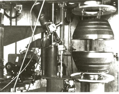
The f i r s t r e a c t o r in the SNAP p r o g r a m w a s a powder mockup c r i t i c a l a s s e m b l y . A n u c l e a r c r i t i c a l a s s e m b l y w a s needed in 1957 to verify the c r i t i c a l i t y calculations for the z i r c o n i u m h y d r i d e e n r i c h e d U^35 fuel m a t e r i a l . T h i s a s s e m - bly w a s m a d e c r i t i c a l for the f i r s t t i m e in October of 1957, j u s t 6 m o n t h s after the initiation of the development c o n t r a c t . In the f i r s t c r i t i c a l a s s e m b l y , powder p r e s s i n g m e t h o d s w e r e employed to p r o d u c e the r e q u i r e d fuel m o d e r a t o r c o m p a c t s . T h e s e w e r e shaped to a s s e m b l e into two h e m i s p h e r e s . The two h e m i s p h e r e s b e c a m e a c r i t i c a l configuration when brought t o g e t h e r . The s p h e r i c a l g e o m e t r y w a s chosen for convenience
^ P r e s e n t e d at the ARS Space P o w e r S y s t e m s Conference, Santa Monica, California, S e p t e m b e r 27-30, I960.
Work done u n d e r AEC C o n t r a c t : A T ( 1 1 - l ) - G E N - 8 t S u p e r v i s o r , S y s t e m D e v e l o p m e n t a l T e s t i n g
§Supervisor, R e a c t o r O p e r a t i o n s Unit
in the n u c l e a r c a l c u l a t i o n s . F i g u r e 1 shows the g e n e r a l a r r a n g e m e n t of this equipment. Although the n u c l e a r c a l - culations w e r e verified within a v e r y s h o r t t i m e , the c r i t i c a l a s s e m b l y w a s in u s e for over two y e a r s . During this t i m e , it was a valuable s o u r c e of n e u t r o n s of the e n e r g y s p e c t r u m of the SNAP 2 c o r e concept. Many m e a s u r e m e n t s such a s n u c l e a r w o r t h of s t r u c t u r a l m a t e r i a l s , coolants, and effec- t i v e n e s s of r e f l e c t o r m a t e r i a l s w e r e c a r r i e d out. Such m e a s u r e m e n t s w e r e e s s e n t i a l for the SNAP 2 design since the n u c l e a r c o n t r o l for this concept is a c c o m p l i s h e d by m o v a b l e r e f l e c t o r sections allowing n e u t r o n s to e s c a p e or be r e f l e c t e d .
III. SNAP E x p e r i m e n t a l R e a c t o r
Simultaneously with the o p e r a t i o n of the powder c r i t i c a l facility, design c a l c u l a t i o n s w e r e c a r r i e d out for the design of the f i r s t power d e m o n s t r a t i o n r e a c t o r . T h i s w a s called the SNAP E x p e r i m e n t a l R e a c t o r . The operating conditions w e r e 50 kw t h e r m a l power, 1200°F exit t e m p e r a t u r e . The m o s t significant change needed in going from the powder c r i t i c a l configuration to a power configuration w a s the p r o - vision of coolant c h a n n e l s . A r m e d with the r e s u l t s of m a n y t e s t s on the powder c r i t i c a l a s s e m b l y , the c o r e w a s r e - designed to u s e solid cylinder fuel e l e m e n t s . T h e s e w e r e a r r a n g e d on a t r i a n g u l a r l a t t i c e so that the c o m p l e t e d a r r a y of 61 e l e m e n t s f o r m e d a hexagonal p r i s m . T h i s a p p r o x i - m a t e d c y l i n d r i c a l g e o m e t r y which r e s u l t e d in a s o m e w h a t h e a v i e r c o r e than the s p h e r i c a l configuration. This cost in additional weight bought a c o m p a r a t i v e l y s i m p l e configura- tion with well defined coolant p a s s a g e s f o r m e d by the cusp
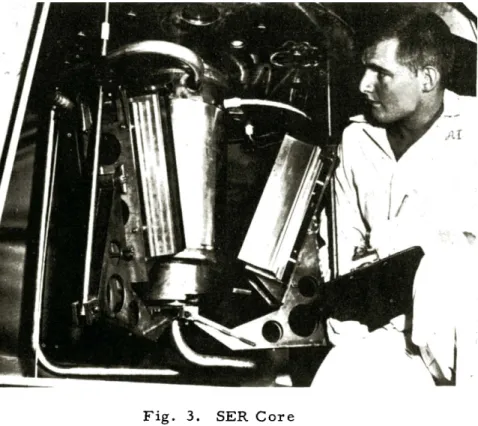
shaped s p a c e between adjacent fuel e l e m e n t s . The g e n e r a l a r r a n g e m e n t of this c o r e is shown in F i g u r e 2. A photo of the SER c o r e is shown in F i g u r e 3.
N u c l e a r c o n t r o l w a s achieved with t h r e e s e m i - c y l i n d r i c a l r o t a t a b l e sections of the r e f l e c t o r . N u c l e a r shutdown w a s achieved by a r r a n g i n g the r e m a i n d e r of the e x t e r n a l r e f l e c t o r in hinged s e c t i o n s which could drop away f r o m the c o r e tank.
Six b e r y l l i u m p i e c e s w e r e needed within the c o r e tank to fill the s p a c e between the hexagonal fuel a r r a y and the tank w a l l . The fuel m a t e r i a l w a s z i r c o n i u m alloyed with 7 w / o of fully e n r i c h e d u r a n i u m h y d r i d e d to 6 x 1 0 " a t o m s of hydrogen p e r cubic c e n t i m e t e r s .
E u t e c t i c s o d i u m - p o t a s s i u m w a s s e l e c t e d for the p r i m a r y coolant, in o r d e r to e l i m i n a t e s y s t e m s t a r t u p h e a t e r s . T h e weight of the SER c o r e , tank, r e f l e c t o r m a t e r i a l , and n e c e s - s a r y h a r d w a r e is about 250 p o u n d s .
The SER r e a c t o r w a s p l a c e d in o p e r a t i o n in S e p t e m b e r 1959. By N o v e m b e r 1 it had o p e r a t e d at 50 kwt and 1200°F outlet coolant t e m p e r a t u r e . On A p r i l 23, I960 the r e a c t o r c o m p l e t e d a 1000 hour continuous t e s t at the above design conditions. It h a s a c c u m u l a t e d a total of 1/3 of a full power y e a r to d a t e . The g e n e r a l a r r a n g e m e n t of the t e s t i n s t a l l a - tion is shown in F i g u r e 4. T h i s w a s d e s i g n e d with the single p u r p o s e of testing the SNAP c o r e . The h e a t t r a n s f e r s y s t e m is a r r a n g e d with an i s o l a t e d p r i m a r y loop for containment and shielding of the r a d i o a c t i v e p r i m a r y coolant. The s e c o n d - a r y coolant s y s t e m is n o n r a d i o a c t i v e and d u m p s the e n t i r e heat load to the a t m o s p h e r e . T h i s is a c c o m p l i s h e d by m e a n s of an a i r b l a s t heat e x c h a n g e r . In this t e s t only the r e a c t o r h a s any r e s e m b l a n c e to flight configuration. P u m p s a r e t h r e e p h a s e l i n e a r induction units so that rotating shaft s e a l s a r e avoided.
During o p e r a t i o n s to date, m a n y m e a s u r e m e n t s have been m a d e which verify and refine the n u c l e a r calculations and heat t r a n s f e r c a l c u l a t i o n s involved in the design of the SNAP 2 r e a c t o r , t h e s e m e a s u r e m e n t s include:
T e m p e r a t u r e coefficient of r e a c t i v i t y P o w e r coefficient of r e a c t i v i t y
E x c e s s r e a c t i v i t y
W o r t h of safety e l e m e n t W o r t h of c o n t r o l e l e m e n t
W o r t h of fuel e l e m e n t s in v a r i o u s c o r e l o c a t i o n s E q u i l i b r i u m xenon defect.
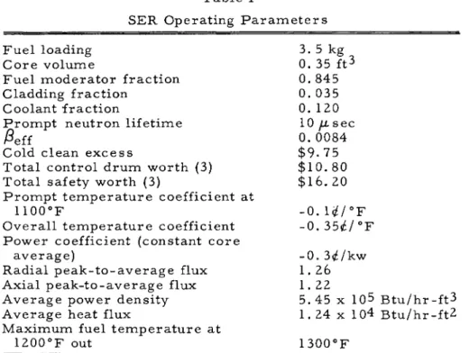
The SER o p e r a t i n g p a r a m e t e r s a r e shown in T a b l e I.
M e a s u r e m e n t s of this type c o n f i r m the SNAP 2 design and add new information for future d e s i g n s . P e r h a p s the m o s t significant point in the o p e r a t i o n of the SER to date is the p r o v e n capability of operating continuously and r e l i a b l y at full SNAP 2 design power and t e m p e r a t u r e of 50 kw t h e r - m a l and 1200°F outlet t e m p e r a t u r e r e s p e c t i v e l y .
IV. SNAP D e v e l o p m e n t a l R e a c t o r - I
The final design of the second SNAP type power r e a c t o r called SNAP D e v e l o p m e n t a l R e a c t o r - I (SDR-I) is now n e a r l y completed, with s t a r t u p for t h i s r e a c t o r scheduled for J a n u a r y 1961. The g e n e r a l configuration of this r e a c t o r c o r e is the s a m e a s the SER, but s e v e r a l m a j o r changes w e r e m a d e a s a r e s u l t of optimization for m i n i m u m weight and m a x i m u m r e l i a b i l i t y . T h e s e changes included reducing the n u m b e r of fuel e l e m e n t s f r o m 61 to 37 with an a p p r o p r i - ate i n c r e a s e in rod d i a m e t e r . C o n t r o l is now a c c o m p l i s h e d
Table I
SER Operating P a r a m e t e r s F u e l loading 3. 5 kg
C o r e volume 0. 35 ft3
F u e l m o d e r a t o r fraction 0. 845 Cladding fraction 0. 035 Coolant fraction 0. 1Z0 P r o m p t n e u t r o n lifetime 10 μ sec
/ 3e f f 0. 0084
Cold clean e x c e s s $ 9 . 7 5 Total control d r u m w o r t h (3) $ 1 0 . 8 0
Total safety w o r t h (3) $16. 20 P r o m p t t e m p e r a t u r e coefficient at
1100°F - 0 . 1 # / ° F O v e r a l l t e m p e r a t u r e coefficient - 0 . 35f£/°F
P o w e r coefficient (constant c o r e
a v e r a g e ) - 0 . 3 ^ / k w Radial p e a k - t o - a v e r a g e flux 1. 26
Axial p e a k - t o - a v e r a g e flux 1. 22
A v e r a g e power density 5.45 x 10^ B t u / h r - f t ^ A v e r a g e heat flux 1. 24 x 1 θ4 B t u / h r - f t ^ M a x i m u m fuel t e m p e r a t u r e at
1200°F out 1300°F with two s e m i - c y l i n d r i c a l r e f l e c t o r sections as c o m p a r e d to
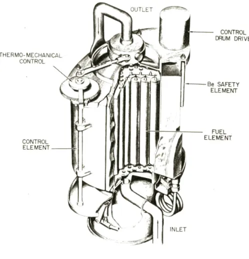
the t h r e e u s e d in the SER. In a s i m i l a r m a n n e r , only two shutdown sections of r e f l e c t o r a r e u s e d in the SDR-I. In approaching the flight configuration w h e r e g r a v i t y cannot be u s e d for e l e m e n t actuation, the shutdown sections a r e spring loaded to o p e r a t e independently of the e a r t h ' s g r a v i t a t i o n a l f o r c e . F i g u r e 5 shows the g e n e r a l a r r a n g e m e n t of SDR-I.
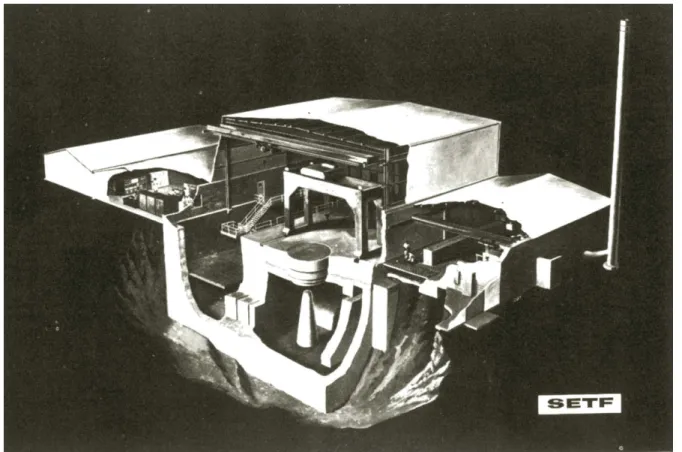
Optimization and r e - d e s i g n have r e s u l t e d in a total weight for c o r e , tank, r e f l e c t o r m a t e r i a l s and r e l a t e d h a r d w a r e of about 200 pounds. This is a net saving of 50 pounds over the SER design. F u e l specifications a l s o changed a s a r e s u l t of the weight optimization studies so that it now c o n s i s t s of Z r + 10% fully e n r i c h e d u r a n i u m . This alloy will be hydrided to 6.5 x 10^2 a t o m s of hydrogen p e r cubic c e n t i m e t e r of fuel m a t e r i a l . The SDR-I will be a r r a n g e d to o p e r a t e the f i r s t complete v e r s i o n of the P o w e r C o n v e r s i o n S y s t e m . All of the individual components involved in this s e r i e s of t e s t s will be of the flight design but the o v e r a l l a r r a n g e m e n t will be one of convenience for installation, operation, and m a i n - t e n a n c e . A special building ( F i g u r e 6) called the SNAP E n v i r o n m e n t a l T e s t F a c i l i t y (SETF), is n e a r i n g completion and will be used for the SDR-I power t e s t s as well a s for final m o d e l s of the SNAP 2.
Conclusion
Design and development to date has r e s u l t e d in a very- w o r k a b l e , r e l i a b l e SNAP 2 r e a c t o r of d e m o n s t r a t e d capability.
While the p r e s e n t configuration would a p p e a r to bè a c c e p t a b l e for flight, further weight r e d u c t i o n is p o s s i b l e . C o n s i d e r a b l e w o r k r e m a i n s to be done in the a r e a of e n v i r o n m e n t a l t e s t i n g . This w o r k will be p r i m a r i l y c o n c e r n e d with the durability of the r e a c t o r c o r e (and power c o n v e r s i o n s y s t e m ) when s u b - j e c t e d to shock and v i b r a t i o n r e s u l t i n g from vehicle launch and a t t a i n m e n t of orbit. In addition, r a t h e r s e v e r e m e c h a n i - cal loads a r e likely to be e n c o u n t e r e d on the ground, during shipping, and set up. As a r e s u l t , a n a l y s i s and evaluation of e n v i r o n m e n t a l conditions, which have long been c o m m o n - p l a c e in the development of r o c k e t s and m i s s i l e s , a r e now being applied to n u c l e a r power p l a n t s . This is being c a r r i e d out by a strong a n a l y t i c a l effort evaluating all of the launch and flight conditions that can be identified. In p a r a l l e l , l a b - o r a t o r y t e s t s involving the u s e of shock m a c h i n e s and v i b r a - tion m a c h i n e s which can s i m u l a t e the m e c h a n i c a l loads in- volved in delivering a n u c l e a r power plant into s p a c e a r e u n d e r w a y .
The final SNAP 2 flight r e a c t o r will be v e r y s i m i l a r to the SDR-I design but will have been further o p t i m i z e d for m i n i m u m weight and m a x i m u m r e l i a b i l i t y . The p a r a m e t e r s of the SNAP 2 r e a c t o r a r e shown in Table II.
T a b l e II SNAP R e a c t o r
SNAP 2 P o w e r
Coolant t e m p e r a t u r e out Coolant t e m p e r a t u r e in C o r e v o l u m e
Rod d i a m e t e r N u m b e r of r o d s NH
U r a n i u m F u e l loading A v e r a g e heat flux P o w e r density Weight:
F u e l m o d e r a t o r e l e m e n t s B e r y l l i u m r e f l e c t o r V e s s e l and s t r u c t u r e
Total
50 kw t h e r m a l 1200°F
1000°F 0. 3 ft3 1.25 in.
37 6. 5 x 10^2 a t o m s / c c 10 w / o
4. 0 kg
17, 000 B t u / h r - f t2 0. 165 M w / f t3 120 pounds
70 35
225 pounds
A SNAP reactor will be the first reactor to survive a rocket launch and the space environment.
Fig. 1. Critical Assembly Machine
OPERATING POSITION
SCRAM POSITION
\CORE VESSEL CONTROL ELEMENT Be CONTROL
DRUM REACTOR
CORE
END &
„REFLECTOR
BERYLLIUM
Fig. 2. SER (Core Schematic)
SAFETY ELEMENT
Fig. 3. SER Core
00 00
ΓΠ TO
CO
THERMO-MECHANICAL CONTROL
CONTROL ELEMENT
INLET
CONTROL DRUM DRIVE
Be SAFETY ELEMENT
FUEL· . ELEMENT
Fig. 5. SNAP 2 Reactor (SDR-I)
o
O
-<
co CO