TECHNOLOGY OF LUNAR EXPLORATION
S U P P L Y TRUCK TO THE MOON D. H. Dickstein1
General Electric Company, Philadelphia, Pa.
A B S T R A C T
In designing a spacecraft to transport one particular payload (a robot roving vehicle) to the moon, it was found advantageous to make the spacecraft self-sufficient, i . e . , able to land on the moon without aid from its payload. With this self-sufficiency, the spacecraft b e - came a general purpose truck that could support the first lunar explor- e r s and later supply manned lunar bases. The logical design of such a spacetruck is formulated in this paper. Chief criteria for the d e - sign are that the landing maneuver be simple, that a safe landing can be made despite small e r r o r s in the maneuver, and that the payload can be unloaded without mechanical aids.
LAUNCH
Payload Weight
The major question concerning Earth launch is booster size vs assembly in orbit. A spacetruck would have little influence in this decision, since freight can be sent to the moon in small or large packets in contrast with manned missions, each type of which has its corresponding minimum escape weight. Inversely, the booster size vs assembly decision would influence the size of a spacetruck but would have little influence on its mission or configuration. Regard- less of the decision, it would probably land direct from Earth, not from lunar orbit, and its propulsion, structure, and guidance would be little affected.
The booster vs assembly in orbit decision would set the maximum possible payload weight of the spacetruck but possibly not the payload weight finally selected. It may cost fewer dollars per pound of pay- load if the payload is small. This is a complex question depending on how rapidly booster, pad, and ground support costs rise as booster size increases vs how rapidly these costs rise as the number of
Presented at the ARS Lunar Missions Meeting, Cleveland, Ohio, July 17-19, 1962.
-'-Systems P r o j e c t Engineer, M i s s i l e and Space D i v i s i o n .
boosters increases. The question depends as well on an even more difficult prediction - how quickly can a load of supplies be used by the lunar base vs the added weight and lunar handling to protect the supplies for longer periods .
Sizing of the spacetruck can therefore wait until the manned m i s - sion is settled, and one can validly proceed to select a spacetruck d e - sign. Before doing so, however, two launch factors will be touched on.
Supplies Delivered Any Day
Restricting the days of the month when a payload can be delivered is undesirable. Numerous deliveries during the allowable period and stockpiling for the remainder of the month are undesirable for at least three reasons :
1. The consequent near-salvo launchings from Earth would r e - quire prohibitive launch complexes.
2. Large scale storage on the moon of certain supplies would require extensive thermal insulation and perhaps meteorite shielding.
3. Emergencies may require daily launch readiness.
One technique permitting daily delivery is for the spacetruck plus its escape booster to enter an Earth parking orbit, coast to the appro- priate point, and fire out of orbit to the moon, adding the requisite 10, 000 fps for injection. An alternate to the parking orbit is to vary throughout the month the launch azimuth. By varying the launch azimuth between about 45 and 110 , the moon can be hit on all but several days of the month.
The parking orbit is an extra operation in the lunar mission, r e - quiring guidance into and out of the orbit and an engine restart after minutes to an hour of coast. On the other hand, varying the launch azimuth may not fit the down-range instrumentation complex for manned flights and may conflict with range safety and political con- siderations.
Coast in Earth orbit has been introduced to allow hitting the moon on any day of the month. There are other considerations tending to eliminate certain periods of the month for lunar landings. When the dark side of the moon is toward Earth, supplies other than, say, c r y o - genic fuel might not be landed because of the need for insulation until the sun rose. There will also be guidance problems restricting periods of flight, arising from the relative geometries in space of references. A star reference suggests itself, rather than Earth or the sun, to at least minimize the variations in this problem. D e -
T E C H N O L O G Y O F LUNAR EXPLORATION
termination of the lunar local vertical, essential to the retrothrust maneuver, would be done with horizon sensors, at least at higher approach altitudes. Although accomplished easier when the moon is
illuminated, this can still be done using heat radiation from the moon when it is dark and hence is not another restriction.
TRANSIT
Transit to the moon for the spacetruck will be similar to that for Jet Propulsion LaboratoryTs Ranger and Surveyor. The only activity of the spacetruck during transit is the midcourse corrections it makes to its trajectory to nullify initial e r r o r s due to launch guidance and propulsion inaccuracies. Otherwise, the spacetruck is in freeflight and need only maintain its design temperatures and generate on the order of 100 w for a tracking beacon, telemetry, and attitude control.
Attitude would be with the payload facing the sun and the fuel tanks in shadow, in the event cryogenic fuel is used for retrothrust. Solar cells for power would be fixed to the spacetruck ramp, eliminating panel deployment. With such an attitude, interrupted briefly once or twice for the midcourse corrections, temperatures of the payload, the electronics and batteries in the platform, and the retrothrust fuel should be predictable and, therefore, maintainable passively. A t t i - tude control to the sun will be a simple matter, with third axis control by an Earth or star sensor.
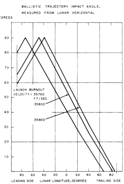
Midcourse correction is one of the two critical operations of the entire mission, the other being retrothrust. The need for midcourse correction is evident from Figure 1, which shows the sensitivity of the ballistic impact point to launch and burnout e r r o r s . Even hitting the moon, much less hitting within 10 miles of the target, is i m - probable without midcourse correction.
Sensitivity increases for impact points nearer the edge of the visible disc. The impact point considered in Figure 1 is near the center of the disc. Figure 1 considers the following launch and burn- out e r r o r s :
V = burnout velocity, fps
R = distance from Earth center, naut. miles
b = Earth centered angle defined by the powered ascent tra- jectory (i. e . , the angle between Cape Canaveral and the booster burnout point)
y = injection angle (with respect to local horizontal)
V = heading from Cape Canaveral a = right ascension of launch point
APPROACH
Direct Landing vs Landing From Orbit
A manned landing should be made from orbit to allow abort and return to Earth and to give the opportunity for selecting a landing site from the sizable swath of the moon observed from orbit. Were one identical spacetruck design to transport freight as well as manned payloads, it would be forced to land the freight from orbit, by virtue of the priority of the manned payload. However, freight should not be landed from orbit for the following reasons:
Of the three operations required to land from orbit - orbit, d e - orbit, and land - orbit and de-orbit are each about as complex as the single operation of landing from orbit. The landing from orbit may be more difficult than the direct landing because it will begin from a flight path initially parallel to the moon's surface rather than s o m e - what vertical to the surface, as with many direct approaches. Land-
ing from a flight path initially parallel requires extremely high guidance and propulsion accuracy to land at a selected site, or alternately large quantities of fuel for subsequent lateral corrections while hover- ing. In contrast, a direct landing benefits in site accuracy from the midcourse corrections.
The advantage o f f e r e d by the o r b i t of s e l e c t i n g a landing site is valid only if a sophisticated sensor and selector are aboard the craft. The sophistication required can practically be attained only by a man. A s to a television sensor aboard the craft and a human s e l e c - tor on Earth, problems arise in television discrimination, the rapidity of the sensing-selecting-sensing loop, and the rapidity of the selection- activation-selection loop.
The energy difference in landing from orbit vs landing direct d e - pends on particulars of the two approaches. The velocity change does not differ more than a few hundred feet per second between a typical direct landing and a typical landing from orbit.
Quite possibly one spacetruck configuration could, upon modifica- tion, accommodate landings either direct or from orbit. Major changes
T E C H N O L O G Y O F LUNAR EXPLORATION
would be required in guidance equipment, and the manned mission from orbit would bring questions of engine redundancy. This possi- bility of a dual-purpose spacetruck should be studied after the Apollo lunar landing mission is selected. If the Apollo mission is to be a shuttle between a moon-orbiting mother craft and the moon, then the spacetruck presented here is limited to freight.
Slant Approach
The spacetruck approaching the moon on a direct trajectory from Earth will approach along one path that is a member of a family of paths. The particular member along which the spacetruck approaches corresponds to the landing site previously selected: This path makes a certain angle with the lunar v e r t i c a l ; thus, corresponding to each landing site is an approach path angle. Figure 2 shows the approach path angle for various landing sites; computations for this figure w e r e two -d ime ns ional.
Vertical approach paths, i. e. , paths coming in along a moon
radius line, are considerably easier to land from than slant approaches.
This is because :
1. The retrothrust vector need be pointed in only one direction throughout retrothrust.
2. This direction of retrothrust (along the vertical) can easily be sensed.
3. The attitude of the spacetruck need not be reoriented during the landing maneuver.
4. Only altitude need be sensed and not lateral velocity, at least until the end of the landing maneuver, when small lateral velocity e r r o r s should be sensed.
Schemes can be generated to make perfect landings from slant approaches. The problem is, as usual, to find a simple scheme.
Whatever the scheme, it must have means for sensing when to thrust and in what direction to thrust. Several techniques to do this a r e :
1. Set up about the moon what can loosely be termed a field of standing microwaves, by beaming microwave energy from Earth, reflecting ic off the moon, and sensing it by the space-
2. Pre-land beacons on the moon.
3. Put all sensing and computing intelligence aboard the space- craft.
A variant of this last technique, all intelligence aboard the space- craft, is a television camera aboard the spacetruck and a human on Earth, interpreting the pictures and commanding thrust. However, television would be additive and it would not replace the automatic intelligence in closed loop aboard the spacetruck. Television cannot accurately measure altitude to determine when to thrust or measure velocity direction to know where to thrust. A t b e s t , t e l e v i s i o n p e r m i t s site selection and local terrain avoidance, commanded from Earth.
The technique using a field of microwaves has a transmitter on Earth and a r e c e i v e r aboard the spacecraft, thus saving spacecraft weight. The spacecrafts velocity vector is measured by using m i c r o - wave fields set up by reflection of unmodulated continuous waves from the moon. By using modulated waves, altitude is measured. Experi- ments on Earth using this technique are being conducted. Its stage of development is not sufficiently advanced to choose it now for the spacetruck. It is described in Ref. 1.
Beacons on the moon can be used to measure the spacecraft v e l o - city vector, its altitude, and lateral position. However, the beacons must have been previously landed, be it a hard or soft landing, and it is required of the spacetruck that it be capable of making the first landing. Moreover, even were beacons previously landed, their relative positions must be known accurately, which can perhaps only be realized with a fairly complex beacon.
It is, therefore, decided to put all intelligence aboard the space- truck.
RETROTHRUST General Criteria
The criteria for retrothrust have been much discussed and r e - ported on during the past two years, particularly under the impetus of the Ranger and Surveyor programs. These criteria have considered
TECHNOLOGY OF LUNAR EXPLORATION
retrothrust primarily when the approach path is vertical. For v e r - tical approaches, a broad outline of the retrothrust phase is as follows :
1. Retrothrust is to be accomplished in two stages: first at a high thrust level, and later at a low thrust level. The high thrust level nulls most of the approach velocity with minimum fuel expenditure. The low thrust level precisely removes the spacetruck residual velocity.
2. Two retrothrust engines are used for two different thrust levels. One engine to cover the entire thrust range appears impractical.
3. The large engine thrusts at a continuous constant level. The small engine has either modulated thrust operating continuously or a constant thrust level operating in bursts.
4. The large engine is ignited at high altitude by radar reflected from the moon. Radar transmitter power is reasonable, since it begins operating at an altitude of only about 100 miles.
This is the "marker" radar. The large engine burns out
rather than being cut off. This factor of simplicity is tolerable, since the retrothrust sequence is designed for burnout at a sufficiently high altitude (about 5 miles) that burnout disper- sion can be absorbed in the vernier phase.
5. Control during the coarse retrothrust phase is simply to
maintain thrust along the vertical. This is done with an inertial platform to eliminate the need for sensing. Sensing through the large engine*s exhaust may be difficult. Since the large engine is rigidly connected to the spacetruck, not gimbaled, control of the thrust direction implies control of the spacetruck attitude.
6. The small engine is controlled (in either thrust level or dura- tion of thrust pulses) by radars measuring altitude and the velocity vector.
Working within this broad outline, the open literature on tradeoffs has flourished. Traded-off have been ignition altitude, burnout altitude,
thrust level, number of vernier thrust pulses, smoothing time, etc.
When the approach path is not vertical, the retrothrust maneuver becomes appreciably more complex. The source of this complexity
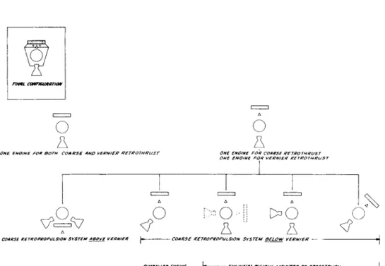
is the need to remove the lateral component of the approach velocity as well as the vertical component. Configurations to remove lateral velocity are shown in Figure 3. The configuration having one engine fixed to the spacetruck is chosen here. Having made this choice, the necessity now presents itself for slewing the spacetruck after, and possibly during, retrothrust.
Coarse Retrothrust
Having chosen one body-fixed engine, the remaining major choice defining the coarse retrothrust phase is the direction of thrusting.
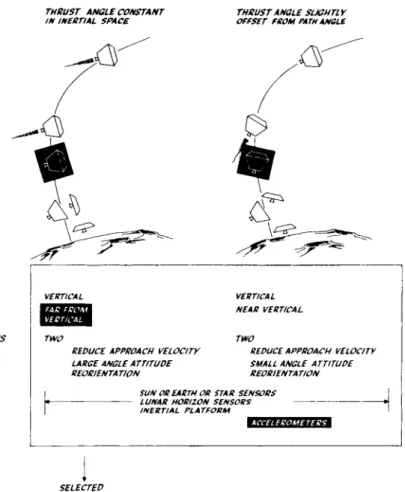
The major criterion for direction of thrusting (or directions of thrust- ing when it is variable) is that at coarse retrothrust burnout the spacetruck has no lateral velocity. This allows the vernier phase to concentrate on very accurately removing vertical velocity for a soft touchdown. Such a direction can be f o u n d - - m o r e o v e r , one that i s constant in inertial space. The next criterion is whether such a d i r e c - tion of thrusting can be found which additionally rotates the space- truck's longitudinal axis to the vertical at burnout. Then at coarse burnout, one could immediately begin sensing for vernier thrusting without an interim slewing of the spacetruck axis to the vertical.
Perhaps a variable direction schedule can be found to accomplish this, but the schedule would be too complicated for simple guidance.
A variable direction can be found which nearly accomplishes this additional criterion of vertical spacetruck axis at burnout with fairly simple guidance. This thrust direction is an offset from the path direction by a constant small angle. At coarse retrothrust burn- out, the spacetruck axis must still be slewed back to the vertical but through the small angle. For a 45 path approach angle and typical initial conditions, this offset angle is about 10 .
The constant direction for thrusting is chosen, not the variable direction, for these reasons:
1. Guidance is simpler. Essentially, only an inertial platform need operate during retrothrust and not accelerometers to sense the changing velocity direction.
2. With variable direction of thrusting, the spacetruck axis still must be slewed back to the vertical at coarse burnout, albeit through a smaller angle.
T E C H N O L O G Y O F LUNAR EXPLORATION
3. With variable direction of thrusting, the coarse retrothrust maneuver is too tightly constrained; there is too little freedom of choice left in other parameters of the maneuver, such as burnout altitude.
Having chosen a coarse retrothrust maneuver requiring slewing of the spacetruck to the vertical at coarse burnout, it must be shown that there is time for slewing.
At coarse retrothrust burnout, the spacetruck is not at rest but intentionally designed to be falling at several hundred feet per second.
This is to insure that, because of coarse retrothrust e r r o r s of various kinds (ignition altitude, fuel impulse, thrust duration, thrust d i r e c - tion), the spacetruck is not rising away from the moon at coarse burnout. A t coarse burnout, the spacetruck is at about five miles altitude. If coarse burnout had occurred higher, more total r e t r o - thrust fuel would have been consumed, since vernier retrothrusting (low thrust level) is less efficient than coarse retrothrusting (high thrust l e v e l ) .
The spacetruck falling at several hundred feet per second, say 500, w i l l fall from five miles to four in 10 sec. This is enough time for orienting the spacetruck's longitudinal axis to the vertical with small jets of only a few tens-of-pounds thrust. Hardly more time can be allowed for orientation, since accurate radar sensing and vernier retrothrusting remain before touchdown.
In brief, the guidance equipment for coarse retrothrust i s :
1. Tracking from Earth which corroborates that the spacetruckfs path will make the predicted angle with the local vertical at retrothrust firing, or which determines this angle if mid- course corrections were inaccurate.
2. A lunar horizon sensor to find the local vertical.
3. A sun sensor or, alternately, an Earth or star sensor for third-axis reference.
4. An inertial platform that is aligned with the vertical and with the third-axis reference. The thrusting direction is m e a s - ured with respect to the platform. The spacetruck longitudinal
axis is brought back to the vertical immediately after coarse retrothrust burnout.
5. A high altitude radar to measure altitude for retrothrust firing.
Landing from a slanting rather than vertical approach requires more coarse retrothrust fuel, since the thrust direction is held a few degrees from the velocity direction to turn the path downward to the vertical. This extra fuel amounts to only a few per cent of the pay- load. The expenditure of extra fuel is inescapable for slant approaches and is probably most economically done as described, unless complex guidance is used.
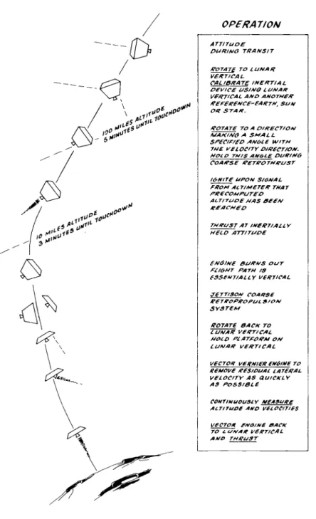
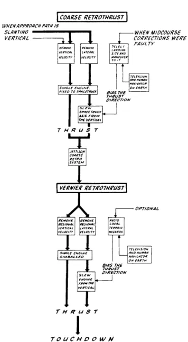
Figure 4 summarizes the landing sequence. Figure 5 summarizes the selection of guidance.
Site Selection
The preceding section considered how to accomplish the basic objective of the landing phase, which is velocity reduction. Involved with velocity reduction is the operation of orienting the spacetruckTs longitudinal axis to the vertical, which was also considered. There remain two more operations to be considered during the landing phase:
gross site selection and local terrain avoidance. Neither operation is absolutely necessary in the same sense as velocity reduction and attitude orientation. Both operations require television viewing of the moon from the spacetruck and a human navigator on Earth. A s to two alternatives to television, tracking from Earth and lunar beacons, tracking will not be accurate enough and cannot provide the local sensing necessary, and lunar beacons have been eliminated as a groundrule.
Gross site selection is an emergency operation to be performed only if the midcourse corrections had greater than nominal e r r o r s . Midcourse corrections with nominal e r r o r s will place the spacetruck in a window above the moon no more than 10 miles from the target center of the window. With such precision, the spacetruck can p r o - ceed to land in numerous areas of the moon without further gross landing site selection. Gross site selection should be made before retrothrusting, above about 100 miles altitude, since large lateral travel near the moon's surface burns fuel at a prohibitive rate. A l s o , television during retrothrusting, with vibration and through the exhaust
TECHNOLOGY OF LUNAR EXPLORATION
plume, is unlikely. Since it is made before retro thrusting, gross site selection cannot remove e r r o r s in retrothrusting. Fortunately these e r r o r s should be small, nominally resulting in a one-mile lateral e r r o r at touchdown.
Site selection consists of the following operations:
1. Television inspection of the lunar area being approached. The inspection will corroborate Earth tracking in determining that midcourse corrections put the spacetruck on its design course, or, if this is not the case, the inspection together with track- ing will determine which course the spacetruck is on.
2. Knowing the spacetruck1 s course, the navigator on Earth can predict the area the spacetruck will be over at initiation of retrothrust.
3. While the spacetruck is approaching this area (a period of a few minutes), the navigator will search maps of the area for landing sites and select one. (This is, of course, an o v e r - simplification. There will be display screens, colored lights, and many participants with headphones. )
4. Computations will be made of corrections to the nominal retrothrust maneuver, to land in the newly selected area.
5. A s the spacetruck closes on the altitude for retrothrust, t e l e - vision viewing of the area beneath w i l l confirm the location of the landing site selected from the maps.
6. The thrusting direction correction to the nominal retrothrust maneuver is telemetered to the spacetruck, and at the preset altitude the engine f i r e s .
Site selection is limited by the resolution of the television, the judgment of the human navigator on Earth, and the fuel required to make a lateral correction.
Resolution by the television system - camera, transmitter, and display on Earth - is sufficient to give the human navigator enough information to avoid crater rims and multipitted regions. From about 100-miles altitude, television can resolve objects several hundred feet apart, over an area 50 miles in diameter. The exact resolution
depends chiefly on the field-of-view flexibility built into the optics.
Resolution of good photographs taken from Earth is several thousand feet. It is interesting to note that the balloon-borne camera of Stratoscope II, above much of Earth1 s atmosphere, would have a resolution (400 ft) about that of the television.
The exceedingly complex question of the human navigator's judg- ment involves depth perception, recognition of landmarks, display and computational equipment, etc. This paper is confined to noting that the navigator must first ascertain from his screen whether there is indeed an e r r o r in the f reef light approach path and, if there is an e r r o r , where a smooth landing site is. Then the computation for the change in thrust direction must be made and the command given.
This must all be done quickly, since the spacetruck falls 100 miles toward the moon in one minute. Although viewing could begin several thousand miles from the moon, it is not until the spacetruck is lower that the critical sensing and judging could be done. At lower altitude, lunar details can be seen, and the spacetruck is nearly over the land- ing area. Note that the celebrated 2-1/2 sec. round trip of a signal to the moon will be relatively only a minor difficulty.
In addition to the fuel to remove the lateral and vertical approach velocity, one must now thrust to move laterally. This can be done most economically during coarse retrothrust and least economically during hovering. During coarse retrothrust, the additional fuel is burned essentially to move only laterally. During hovering, fuel is also burned to hold altitude ; long hovering would be required to move a reasonable lateral distance when considering accelerating and d e - celerating the spacetruck and the scanning speed of the surface below.
To move 20 miles laterally during coarse retrothrust, additional fuel amounting to 5% of the freight payload must be burned. (This 20 miles lateral travel during coarse retrothrust is to correct for m i d - course e r r o r s and is in addition to the lateral distance traveled during the nominal retrothrust maneuver. ) To move 20 miles laterally during hovering would take at least several minutes. F o r h o v e r i n g a l o n e , fuel amounting to 5% o f the f r e i g h t p a y l o a d burns each minute. O f f - l o a d i n g 5% o f the p a y l o a d to a l l o w f o r l a t e r a l t r a v e l , as an e m e r g e n c y m e a s u r e to counter m i d c o u r s e c o r - r e c t i o n e r r o r s , i s r e a s o n a b l e at l e a s t f o r i n i t i a l f l i g h t s .
The relationship of site selection and local terrain avoidance to normal retro thrusting is shown in Figure 6.
TECHNOLOGY OF LUNAR EXPLORATION
Vernier Retrothrust
The coarse retrothrust maneuver for the slant approach was de- signed to bend the path downward to be vertical at coarse burnout.
The spacetruck axis was then slewed to the vertical after burnout.
From the moment the axis is vertical, the remainder of the landing (the vernier phase) is identical for initial approaches that were slant- ing or vertical. A minor difference is that the slant approach will leave the spacetruck at coarse burnout with more lateral velocity error. The vernier phase consists of:
1. Removing the residual vertical velocity with a variable thrust engine or alternately a constant thrust pulsed engine. A l t i - tude and vertical velocity are sensed with radar.
2. Nulling of the small lateral velocity error by thrusting with the same engine gimbaled over a small angle, and sensing lateral velocity with doppler radar.
Reliability indicated that one vernier engine rather than several be used. The voluminous literature on the vernier phase obviates the need to delve further into it here.
Fuel
Most of the fuel is used for coarse rétropropulsion, in which 95%
of the total approach velocity is removed. The fuel for coarse retro- pro pulsion and the spacetruck1 s configuration are largely independent of one another. The choice of fuel will depend on proven reliability, the fuel used for manned missions, and the fuel's specific impulse, which reflects itself in the degree of cost incentive for transporting larger payloads per spacetruck.
The spacetruck was configured for three different fuels (Table 1) and the weight of the coarse retrothrust module determined. Con- sidered were fuel specific impulse, tanks and casing, insulation, pumps and pressurization, effect on spacetruck structure, etc. The weight breakdown shown in Figure 7 uses an average of these three percentages.
Table 1
Fuel Solid Liquid Storable Cryogenic
Specific impulse, sec 290 320 430
Weight of coarse retrothrust module,
% of total
spacetruck weight
at escape. 62 61 55
The choice of fuel for vernier rétropropulsion will probably be between two Earth-storable fuels, one hypergolic and the other not hypergolic. The payload weight advantage of cryogenic fuel is small since little vernier fuel is burned. A choice of cryogenic fuel for coarse retrothrust would not improve its position for vernier retro- thrust since the two rétropropulsion systems are entirely independent.
The choice of fuel for vernier rétropropulsion will depend on:
1) fire hazard, i. e . , the hardware weight required to insure that fuel lines will not break upon a rough touchdown, spilling residual vernier fuel and 2) guidance for the vernier stage, i . e . , the choice as dic- tated by sensors and computer characteristics, between a variable thrust continuous burn vernier engine and a pulsed engine.
The fire hazard of hypergolic fuels - those which ignite on contact of fuel and oxidizer - is considerably higher than for nonhypergolic fuels. But by the same virtue/vice, instant ignition on contact, a hypergolic fuel is decidedly more reliable when several thrust pulses are required and, moreover, when thrust rise and decay times must be fast.
From guidance considerations, a continuous burn vernier engine having a wide variation in thrust level is optimum for a soft landing.
However, a pulsed engine can be incorporated in the guidance scheme with little difficulty. The increase in touchdown velocity dispersion caused by the pulsed engine is still acceptable. With respect to simplicity of engine construction and engine control, hence reliability, the pulsed engine has the advantage.
TECHNOLOGY OF LUNAR EXPLORATION
CONFIGURATION Payload
The spacetruck transports supplies to the moon. Its configuration is dictated by the requirements that these supplies be landed safely despite an imperfect touchdown and despite a touchdown in rubble or dust and the requirement that the supplies be unloaded without hoists.
These requirements are met by a platform of short height and wide diameter. The short wide platform:
1. Provides a large area for prefabricated structures such as building panels. The elimination of as many fabrication operations as possible by men on the moon may be significant.
2. Allows the center of gravity of the payload to be kept low to minimize toppling tendencies when landing with lateral velocity, or on a slope,or with a tilted attitude.
3. Straddles large boulders and does not sink in soft deep dust.
4. Brings the payload close to the surface, allowing unloading by simply pulling the payload off the platform. The platform edge is tapered to form a ramp for this reason. Men unaided by mechanical equipment can easily unload the platform. Such pedestrian considerations for such an exotic venture may prove to be crucial, at least for early landings.
The spacetruck can be designed without specifying the payload b e - yond its density, which sets the payload center of gravity, which in turn strongly influences the landing gear design. For instance, if the landing gear were a tripod, the length of the legs and their straddle angle would be influenced by the payload density. One may expect payload densities of 100 to 200 l b / f t3.
For a payload covering a circular area 10 ft in diameter, having a density of 100 l b / f t3 and totaling 50, 000 lb, the payload center of gravity would rest 3 ft above the platform top surface or 6 ft above the lunar surface, assuming the landing gear folds away. Assuming a 30 ramp around the platform, a 10-ft diam surface to support the payload yields a spacetruck to fit within a 20-ft diam launch fairing.
Rétropropulsion
It has been shown how the basic purpose of the spacetruck, which is the transportation of supplies, influenced its configuration. How the basic function of the spacetruck, which is the removal of its high lunar approach velocity without the decelerating aid of an atmosphere, influences its configuration will now be examined. This is best seen in Figure 3. The major decisions were in order:
1. Two separate rétropropulsion systems are used, one for coarse, the other for vernier retrothrusting. This is princi- pally because a high and then a low accurate thrust level are required, and one engine cannot conveniently do both.
2. The coarse rétropropulsion system employs only one engine for increased reliability. Only one engine need ignite and burn. Also, if multiple engines were used, large attitude disturbances would be caused by imprecise ignition or burn- ing of one engine, particularly since this would occur during f reef light.
3. Since only one engine is used, it must be below and not above the payload.
4. The coarse rétropropulsion engine is rigidly mounted and the entire spacetruck slewed to direct thrust. Required slewing angles are too large for simple light-weight accommodation if the engine were slewed.
5. The coarse rétropropulsion system is jettisoned after its use, before touchdown. This is principally to permit the payload after landing to rest only a few feet above the lunar surface for simple unloading.
6. The entire coarse rétropropulsion system and not just the engine is jettisoned, principally to avoid breaking fuel lines.
7. The vernier rétropropulsion system employs only one engine for increased reliability.
8. The vernier engine is gimbaled. The spacetruck longitudinal axis must be vertical during the final descent; hence it can not be tilted to remove residual lateral velocity. Gimbal angles are small.
TECHNOLOGY OF LUNAR EXPLORATION
Landing Gear
Retrothrusting has reduced the spacetruckTs vertical velocity to a nominal 10 to 20 fps downward, and the lateral velocity nominally to z e r o . These nominal velocities are achieved at an altitude of 10 to 20 ft. It has been shown that a positive downward velocity rather than no velocity is chosen to eliminate the possibility that, through guidance and propulsion inaccuracies, the spacetruck is rising from the moon at termination of vernier thrust. Falling from a height of 10 ft to the moon, the spacetruck impacts at 10 fps. Adding to this a downward velocity of 10 fps, the spacetruck impacts at 20 fps.
The function of the landing gear is to dissipate the energy in this vertical touchdown velocity of 20 fps and in the lateral touchdown velocity, which will be taken to be 10 fps. There is no problem in finding materials to dissipate the energy from the vertical velocity.
Honeycomb structures, thin walled cylinders, and gas bags can do this for only a few pounds of the material actually dissipating energy. Not all these devices w i l l handle the lateral velocity simultaneously with the vertical, honeycomb with its linear cells being an example. A new structure called Trussgrid can efficiently dissipate the energy in velocities coming from any direction.
The energy is to be dissipated in a stroke whose value is set by the deceleration tolerable by the payload and by the spacetruck struc- ture itself. Earth-launch accelerations will be about 10 g, setting a lower bound. Structural weight of the spacetruck itself is a strong function of acceleration, so there is reason for keeping it low. The only reason for designing to a high deceleration might be to reduce the length of decelerating stroke. A long stroke would imply crumpling tendencies in the gear and toppling tendencies in the spacetruck.
However, the stroke corresponding to a deceleration of 10g with a touchdown velocity of 20 fps is less than a foot, presenting no problem.
Therefore, the spacetruck is designed for a nominal 10g, and so the same structure standards in current use for launch stages and space- craft are maintained. The interrelationship of deceleration and touch- down velocity is restated in Figure 8.
Having defined the energy to be absorbed by the landing gear and the stroke in which this energy is to be absorbed and having suggested devices for dissipating the energy, there remains the selection of landing gear configuration. Configuration depends on the lunar terrain and the touchdown e r r o r s .
The lunar terrain may be found to consist of three surface types, each type presenting a characteristic problem to the landing space- truck :
1. Deep dust, loose or compacted, may cover the vast low lying maria.
2. Hollow rock bubbles a few feet in diameter may cover the interior of craters.
3. The rubble covered highlands may be strewn with boulders ejected from volcanos or meteor impacts.
The extent to which maria cover the moon can be seen from any photograph of the moon. The extent to which craters cover the moon is shown in Figure 9 (2), which also shows crater depth and crater slope. About 10% of the surface is covered by craters.
One should design to land in all of these characteristic types with one landing gear configuration, though of course not to land in the extreme of each type. One designs for this variety because: 1) the actual surface may be unknown or knowledge of it for all regions of the moon too expensive to obtain; 2) guidance errors may force a landing far from the selected site; and 3) reliability will accrue from the repeated use of one configuration.
Guidance and rétropropulsion errors will result at touchdown in a residual lateral velocity and a tilt of the spacetruck axis from the vertical. An error analysis gave the aforementioned 10 fps lateral velocity error. The attitude error cannot exceed, say, 20 , without having caused, as well, severely high vertical velocity at touchdown because of misdirected vernier thrust.
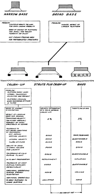
These two factors, a variety of lunar terrain and an off-design velocity vector of the spacetruck, dictate that the energy dissipating device be placed a distance below the platform. The platform then softly contacts the surface a fraction of a second after the energy dis- sipating device. To accomplish this, there are two basic techniques:
the platform is kept at a distance from the initial point of contact either by a rigid strut or by the energy dissipating device itself, such as inflated bags. Figure 10 compares bags with struts having crush- up feet.
TECHNOLOGY OF LUNAR EXPLORATION
The author tends to favor struts, even though they weigh twice as much as a bag system. Considering operations, struts need only be deployed, whereas bags must be inflated and then valved on impact.
Valving is a sensitive and critical operation. The major problem is tolerance of off-design touchdown velocity; one valve mechanism can- not handle off-design velocities without causing the spacetruck to r e - bound. In contrast, simply adding crush-up material to the pads will provide this tolerance. On the other hand, in addition to this weight advantage, bags seemingly could tolerate a wider variety of terrain.
The prospect of a heavily loaded spacetruck mounted on struts and landing in boulders with lateral velocity is not cheerful. Even though material exists which can absorb lateral as well as vertical loads, one must insure that this material makes contact and deforms before the struts contact the terrain. The renderings show bags rather than a tripod of struts, primarily as relief for the lunar craft artist.
Having considered the landing gear per se, note that the spacetruck platform itself is a good contact configuration if the landing gear can- not absorb all the touchdown velocity. The platform has a broad flat bottom to straddle surface roughness or to float in dust and has a
structure that can absorb some energy.
CONCLUSION
The spacetruck consists of two modules: the platform for the pay- load and, beneath it, the rétropropulsion engine and fuel. The plat- form, in addition to supporting the payload, contains all intelligence and power and a small rétropropulsion engine with its fuel. The rétropropulsion module cancels most of the spacetruck's lunar approach velocity. After thrusting, the rétropropulsion module is jettisoned, and the residual approach velocity is cancelled by the small engine in the platform.
The diameter of the circular platform is large, accommodating large prefabricated structures that can quickly be assembled on the moon with few tools and operations. When landed, the payload is only a few feet above the lunar surface by virtue of the prior in-flight jettison of the rétropropulsion module from beneath the platform and by virtue of the short height of the platform. The edge of the platform
is tapered to form a ramp, allowing the payload simply to be pulled off. Hoisting equipment and operations are eliminated. The payload can be manhandled off the platform. The first salient characteristic of the spacetruck is this simplicity it brings to lunar operations.
Payload weight is one quarter Earth escape weight for small space- trucks and a larger fraction for spacetrucks sized to later Saturn boosters.
As a groundrule, it is required that the spacetruck land anywhere on the side of the moon facing Earth. Much of the moon1 s surface is approached along trajectories that slant sharply with respect to the surface. Landings from such approaches are considerably more dif- ficult than from the vertical approaches that have hitherto been given major attention in the literature and in lunar spacecraft design. This difficulty stems from two factors: 1) the landing maneuver now in- cludes lateral as well as vertical retrothrusting and 2) residual e r r o r s at touchdown ( e r r o r s in lateral velocity and in tilt of the spacetruck axis) will be higher.
In addition to landing in all lunar latitudes and longitudes, the groundrule is set that the spacetruck automatically sense and r e t r o - thrust for the landing maneuver. The necessity is ruled out for having television onboard the spacetruck sending pictures to a human pilot on Earth. The reliability of this long range loop is questionable.
Lunar beacons are also ruled out, since the spacetruck is to land in virgin regions. This groundrule dictating spacetruck self-sufficiency simplifies the overall mission and, in this sense, increases r e l i a - bility by eliminating operations.
The spacetruck minimizes the complexity of the landing maneuver by retrothrusting in a direction that is held constant in inertial space.
This direction is preset on Earth and updated during transit to reflect the actual trajectory the spacetruck is following. Thus, the second salient characteristic of the spacetruck is its guidance : it can land automatically, and its landing maneuver is simple.
The spacetruck widens its tolerance for touchdown e r r o r s by its stable, low center of gravity configuration of broad platform coupled with short height. Toppling tendencies are minimized. This configura- tion also has wide tolerance for lunar terrain. It will not sink in soft dust even with a high touchdown velocity. It straddles broken rubble and boulders. The third salient characteristic, then, is the stability of the wide squat landing configuration.
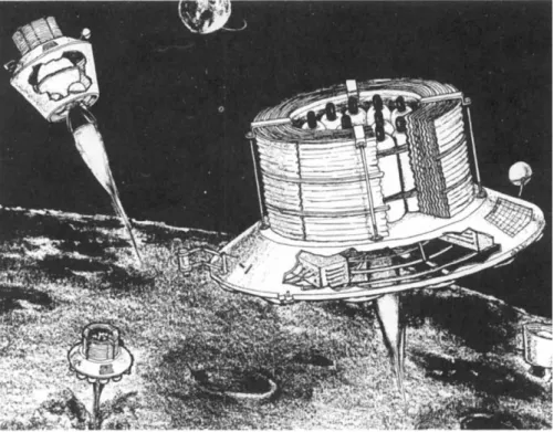
Figure 11 shows the spacetruck making the retrothrust maneuver.
Figure 12 shows it being unloaded on the moon.
TECHNOLOGY OF LUNAR EXPLORATION
REFERENCES
1. Dickey, F. R . , Jr., "Velocity sensing for soft lunar landing by correlation between spaced microwave r e c e i v e r s , " Inst. Radio Engrs. Internatl. Convention Record (1961).
2. K o r n h a u s e r , M . , " T h e crater contribution to roughness of the moon, " A m . Astronaut Soc. Preprint 62-23 (1962).
Fig. 1 Impact point sensitivity
B A L L I S T I C T R A J E C T O R Y I M P A C T A N G L E , M E A S U R E D F R O M L U N A R H O R I Z O N T A L D E G R E E S
8 0 6 0 4 0 2 0 0 2 0 4 0 6 0 8 0 L E A D I N G S I D E L U N A R L O N G I T U D E , D E G R E E S T R A I L I N G S I D E
Fig. 2 Ballistic impact angle
TECHNOLOGY OF LUNAR EXPLORATION
Ο Δ
Ο Δ
PNB eNQINE ΡΟΚ BOTH COARSE AND VERNIEP RETROTHRUST
COARSB RCTROPROPULSION SYSTEM ABOVE VERNIER |- COARSE RETROPROPULSION SYSTEM BELOW VERNIER
OIMBMLLED EMIMi - ENÙINE(S) RIÛIOLY MOUNTED TO SPACE TRUCK -
SPACêTROCKfiOtilPflOP TWO EN6IN£S SPACETRUCK SLiW
Ο
Fig. 3 Selection of rétropropulsion
OPERAIΊΟΝ ATTITUDE
PU RI Mû TRANSIT
KOT AT £ TO LUNAR VERTICAL
CALIBRATE INERTIAL OeV/CE US/Ν Ο L U N A R
VERTICAL AN Ο ANOTHER R£F£R£NC£-£ARTN, SUN OR STAN.
ROTATE TO A DIRECTION MAK'NG A SMALL SP£CI*/£D ANÙLE WITH THE VELOCITY D/R£CT/ON.
HOLD TH/S AN6LE DURINo CO A RS £ RETROTHRUST
IONITE UPON S I ON A L FROM ACT/M£T£R TRAT PRECOMPUTED
ALTITUDE HAS 3ΕΕΛΙ
REACHED
THRUST AT INERT/ALL Y HELD ATT/TUDE
£NÔ/N£ BURNS OUT
fa/6HT RATH /S
ease ν t/ally i/er tica l jettison coarse RETÏOPROPUL son SYSTEM
ROT AT £ BACK TO LUNAR VERTICAL HOLD PLATPORA4 ON LUNAR VERTICAL
veCTOR VERNIERENÙINETO remove Res/dual lateral VELOC/TY AS QUICKLY AS POSSIBLE
CONTINUOUSLY MEASURE ALTITUDE AND VELOCITIES
VECTOR ENÔINE BACK TO L UNAR VERTICAL AND THRUST
Fig. 4 Landing sequence
TECHNOLOGY OF LUNAR EXPLORATION
THRUST ANGLE CONSTANT
IN INERTIAL SPACE THRUST ANGLE SUGHTL Y OFFSET FROM PATH ANGLE
AT BURNOUT PATH ANGLE SPACETRUCK LONGITUDINAL AXIS NUMBER OF OPERATIONS
GUIDANCE EQUIPMENT
FAR FROM VERTICAL TWO
REDUCE APPROACH VELOCITY LARGE ANGLE ATTITUDE REORIENTATION
VERTICAL NEAR VERTICAL
TWO
REDUCE APPROACH VELOCITY SMALL ANGLE ATTITUDE REORIENTATION SUN OR EARTH OR STAR SENSORS LUNAR HORIZON SENSORS INERTIAL PLATFORM
ACCELEROMETERS
SELECTED
Fig. 5 Selection of guidance for retrothrust
WHEN APPROACH PATH IS SLANTING
VERTICAL
COARSE RETROTHRUST \
remove vertical
Rénove
1
L AURAL
SELECT L AHOINÙ sue AHO
I
-WHEN MIDCOURSE CORRECTIONS WERE
FAULTY
Tf if VISION AHO HUMAN
\HAVIUATOR ON EARTH BIAS THE THRUST DIRECTION
SPAC6 TRUCK
\AXIi PROM THE VERTICAL Τ Η R u s r
JETTISON COARSE RETRO SYSTEM
I VERNIER RETROTHRUST]
3 Z
RESIDUAL RCMOV6 VERTICAL VELOCITYREMOVE R€SIDUAL\
LATERAL VELOCITY
AVOID LOCAL TERRAIN HA 2AR OS
I
TE L EVI S ION AND HUMAN NAVIOATOR ON EARTH
SLEW ENOINE PROM THE VERTICAL
T
BIAS THE 7HRUST DIRECTION
T H R U S T
ΤΟ UC H D OWN
I
Fig. 6 Site selection and terrain guidance
T E C H N O L O G Y O F LUNAR EXPLORATION
WEIGHTS
ESCAPE WEIGHT
(100% * 15000 POUNDS)
= 100%
FAIRING
PAYLOAD
PLATFORM /Z
FUEL STRUCTURE GUIDANCE
COARSE RETROPROPULSION 59
FUEL STRUCTURE
ADAPTER TO ESCAPE BOOSTER Fig. 7 Weight breakdown
ERRORS OF GUIDANCE AND THE VERNIER ENGINE
/OO DECELERATION AFTER TOUCHDOWN
AT LESS THAN ΙΟ 6, NO PAYOFF SINCE (ΑΛΤH LAUNCH 13 /Ο 6
AT Muge THANK>6,$PAC£ Τ BUCK S TgUCTUg/tL AMO Lg*PlN66EAg wfioHT ooes UPP4PIOL Y
FOK OeSION VALUE Of T*/s heloc/ty oom/ivAgp space tpuck \ IS PPOBABLY (3<r) FALLING INSTEAD OF P/S/NO-AT F/HAL Τ H/TUST TERMINAT/ON
ON-OFF
\/£RN/£R ENGINE
>20-
I
VARIABLE THRUST VERNIER EA/OINE
y/û-. <25
/FOOT DECELERATIONSTROKE
AFTER TOUCHDOWN
A I FOOT STROKE IS PEASOMABLE CONSIDfPlNO PACXA0/NÛ FOP LAUNCH AND SPACE TPOVXSTABILITY AT TOUCHDOWN
CPUSN-L/P AMTEP/AL S CAN DISS/PATE TOUCH0OWN eNEPaY IM LESS THAN A f foot sreoKE
Fig. 8 Selection of touchdown velocity
PERCENT OF LUNAR S U R - FACE COVERED BY CRATERS OF GIVEN DIAMETER
1 0 , -
CRATER SLOPE, AVERAGE FROM BOTTOM TO TOP
9 0° r —
CRATER DEPTH CRATER DIAMETER 11—
1000 10,000 CRATER DIAMETER, F E E T
100,000 1,000,000
Fig. 9 Lunar crater characteristics
T E C H N O L O G Y O F LUNAR EXPLORATION
s///s s//s / ///////
MARROW BASE
W/////////////M
/ > ///////// //////>////
BROAD 3AS£
FROBLCN
CENTEROFORAVITY TOO Ν ION FOR OOOD LAMOINO STABILITY AREA OF CONTACT 0F PLATFORM TOO SMALL FOR- ROU6M TERRA/Λ/ OA? DUST NOT ENOUON STACK/NO AREA toe ree/xaetcAT£D STRUCTURES
·///////s//////////t?//////////////// J*/
STRUTS PLUS CRUSH-UP B A US
CRUSH-UP
PROBLEM:
PC A Τ FOR M SNA û S WHEN LATERAL TOUCHDOWN VEL OCITIES ARE PRESENT PLATFORM CRUSHES WHEN TOUCHDOWN ATTITUDE IS T/LTEO
WEIS Η Τ OF LAND! Να If EAR FOR NOMINAL TOUCHDOWN VELOCITY (tO FT/SEC VERTICAL) PERCENT OF TOTAL SPACETRUCK AT ESCAPE
TOLERANCE TO OFF-DESION CONDITIONS AT roue H DOW M
OFF - DESIGN VERTICAL VELOCITY LATERAL VELOCITY TILTED ATTITUDE ABILITY TO STOW IN SMALL VOLUME FOR LAUNCH
IN-FLIGHT PRRRARATION TOC ΕRA NCΕ OF MEAT DURINO CVE RN/EA* ) RETROTHRUST
ADDITIONAL OPERATIONS DU RIMS ENERGY DISSIPATION
ADDITIONAL OPERATIONS TO PROP PLATFORM TO CUNAR SURFACE
INELASTIC DEFORMATION OF A SOLID MATERIAL (CRUSH-UF)
OOOO OOOD OOOO
P>OOAf
OOOD DEPLOYMENT
OOOO
COLLAPSE
THROTTLINO OF OAS
37»
POOR (REBOUND) QUESTIONABLE
OOOO
OOOD
QUESTIONA BLE
INFLATION
QUESTIONABLE
VAL VIKIG
-MO CHOICE YET -
Fig. 10 Selection of landing gear
Fig. 12 Spacetruck being unloaded on the m o o n