Nuclear Inst. and Methods in Physics Research, A 959 (2020) 163521
Contents lists available atScienceDirect
Nuclear Inst. and Methods in Physics Research, A
journal homepage:www.elsevier.com/locate/nima
Two-dimensional conceptual design of a superconducting iron-free opposite field septum magnet
Dániel Barna
a,b,∗, Martin Novák
aaWigner Research Centre for Physics, Budapest, Hungary
bUniversity of Miskolc, Faculty of Material Science and Engineering, Hungary
A R T I C L E I N F O
Keywords:
Septum magnet Truncated cosine theta Superconducting magnet Opposite field
A B S T R A C T
A novel concept of a superconducting iron-free opposite field septum magnet is presented, which could provide a magnetic field jump of 1.4 T between its two domains, with a septum blade thickness of about 4 mm.
1. Introduction
One of the key elements of the extraction systems of particle ac- celerator rings is the septum magnet, which creates two regions with very different values of the magnetic field, in close proximity. For a sharp transition of the field, a physical, current-carrying wall, called the septum blade, separates the two regions. The circulating beam passes through one of these two regions. In the case of fast extraction within a single turn, the beam is kicked into the other region (‘‘extraction region’’) by a fast upstream kicker magnet. When slow extraction over several turns is required, the beam size is gradually increased using a 3rd order resonance excited by sextupole magnets, and particles at large amplitudes are ‘‘sliced off’’ using an electrostatic septum con- sisting of a very thin blade (a stretched foil, or a series of stretched wires) with a high electric field at its external side, which gives the beam a small outward kick, directing it into the extraction region of the magnetic septum. In both schemes, the trajectory of the extracted beam then diverges from the circulating beam downstream of the septum magnet.
Designers must find the best trade-off between the following two requirements. The magnet needs to have a large jump of the magnetic field across the blade, i.e. a large separating power, in order to make the extraction region compact (total length of the septum magnet(s), and distance of the first ring magnet placed downstream of the septum).
On the other hand, the septum blade must be as thin as possible, in order to reduce the requirements on the upstream kicker magnet’s strength, and/or decrease the distance between the kicker magnet and the septum. For a given operating engineering current density𝐽𝑒 in the blade, the blade thickness 𝑑 limits the achievable field jump:
∗ Corresponding author at: Wigner Research Centre for Physics, Budapest, Hungary.
E-mail addresses: barna.daniel@wigner.mta.hu(D. Barna),novak.martin@wigner.mta.hu(M. Novák).
URL: http://wigner.mta.hu/~barna(D. Barna).
𝛥𝐵=𝜇0𝑑𝐽𝑒. Also, a thin blade may cause mechanical problems if high magnetic forces are present.
In the most common arrangement (ZH — zero/high-field) the sep- tum magnet creates zero (or negligible) magnetic field in the region of the circulating beam, and high field at the extracted beam. The ad- vantage of this configuration is the looser requirement on field quality compared to the ring magnets, since the beam passes through the high- field region only once. A typical value is±1% field homogeneity, in contrast to the standard 1 unit tolerance of higher multipoles (10−4of the main multipole component’s magnitude, evaluated typically at 2/3 of the aperture) in ring magnets. For the circulating beam this septum magnet represents a drift space.
Another configuration is the opposite-field (OF) arrangement, where the magnetic field has opposite directions, ±𝐵0 at the two sides of the septum blade. The advantage of this configuration is that there are no net forces on the blade, and therefore it can be made thinner.
Superconducting solutions also benefit from the peak field reduction of about a factor 2 in the coils compared to the ZH configuration for the same separation power𝛥𝐵 = 2𝐵0. This enables higher operating currents, and thereby a higher separation power for the same blade thickness. On the other hand, the circulating beam is running in a high magnetic field, which has to fulfill the strict quality requirements of the ring magnets, also during ramping. This might be an issue (in fact for any magnet around the circulating beam), if significant eddy currents are induced in the support structure of the magnet’s winding. This is the case for example if fast ramping is planned to be combined with magnets based on the canted cosine theta configuration, which is the subject of some recent R&D activities [1–4]. In these magnets the superconducting wires are wound into grooves machined
https://doi.org/10.1016/j.nima.2020.163521
Received 29 October 2019; Received in revised form 17 December 2019; Accepted 23 January 2020 Available online 27 January 2020
0168-9002/©2020 The Authors. Published by Elsevier B.V. This is an open access article under the CC BY-NC-ND license (http://creativecommons.org/licenses/by-nc-nd/4.0/).
D. Barna and M. Novák Nuclear Inst. and Methods in Physics Research, A 959 (2020) 163521 into bulk aluminium or aluminium-bronze ‘‘formers’’. A similar concept
– although with different geometry – is also a possible realization scheme for the magnet proposed in this article. For the OF configuration the septum must necessarily be ramped following the beam momentum, and the kick given to the circulating beam by the septum must either be integrated into the optics of the ring, or be compensated by other magnets as in [5,6]. In the latter case these extra magnets increase the total effective length of the device, and this solution is therefore disadvantageous when compactness is a primary goal.
Future accelerators may require new solutions for the extraction septa. In order to deal with the unprecedented beam rigidity of the Fu- ture Circular Collider (FCC), two new septum concepts were proposed.
One of them is based on the truncated cosine theta principle [7,8].
The other concept uses the combination of a superconducting magnet and a passive superconducting shield (‘‘SuShi septum’’) [9,10], having the advantage of a relatively thin septum blade despite the large mechanical forces. Future superconducting medical hadron accelerators will require very compact solutions in general, and consequently as thin as possible blades for the extraction septum magnet, for moderate beam rigidities around 6.6 Tm. While the SuShi concept could be scaled down to a few-mm blade thickness with about 1 T magnetic field for the extracted beam, if slow extraction is required, the beam losses necessarily associated with this scheme may (partially) quench the superconducting shield, interfere with the history of the passive, induced persistent currents, and lead to the uncontrolled magnetic state of the shield. The robustness of this configuration in the environment of a medical accelerator or with slow extraction needs to be confirmed by dedicated experiments. This paper presents the 2D concept of an opposite-field iron-free septum magnet with no passive elements and a thin blade.
2. 2D concept
The 2D magnetic field of a𝐽𝑧(𝜗) =𝐽0cos(𝜗)sheet current on a circle of radius𝑅is
|𝐵|=
{ 𝜇0𝐽0∕2 =𝐵0 if𝑟 < 𝑅
𝜇0𝐽0∕2⋅(𝑅∕𝑟)2 if𝑟 > 𝑅 (1)
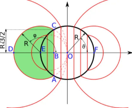
The induction lines (contour lines of the vector potential’s third component,𝐴𝑧) are straight vertical lines within the current sheet, and circles passing through the origin, with a center on the horizontal axis, outside of the current sheet, as illustrated inFig. 1.
Following the recipe of ‘‘truncating’’ a known magnetic field con- figuration, described in [11], one has to select first a closed induction line which splits the 2D plane into two domains. The magnetic field can be set to zero in one of the domains, if a sheet current density
|𝐽trunc|=|𝐵|∕𝜇0is prescribed along this line, and the part of the original current distribution is eliminated within the domain. The direction of the truncating current distribution depends on which domain was chosen to be made field-free. The resulting magnetic field and current distribution satisfy everywhere Maxwell’s equations. A truncated cosine theta septum magnet configuration is usually created by keeping the magnetic field within the truncation line, and setting it to zero outside of it.
A different field configuration can be created by reversing the direction of the truncating currents. Choose the induction line A–B–
C–D–A in Fig. 1for truncation, set the magnetic field to zero within the shaded domain encircled by this line, and eliminate the part A–
E–C of the original cos(𝜗)current distribution. The magnetic field in the domain encircled by the line A–B–C–F–A will remain a pure dipole field𝐵𝑦= −𝜇0𝐽0∕2. The resulting geometry of the sheet currents will be symmetric to the line A–C. The superposition of the current distribution with its horizontal mirror image will result in a field configuration with opposite fields𝐵𝑦= ±𝜇0𝐽0∕2in the two domains A–B–C–D–A and A–
B–C–F–A, respectively. Using the path length parameter 𝑠along the
Fig. 1. Illustration of the induction lines (red) of acos(𝜗)sheet current distribution (thick black circle). The dashed lines show the extensions of the induction lines of the external domain to the interior of the current distribution. (For interpretation of the references to color in this figure legend, the reader is referred to the web version of this article.)
line B–C–D, a building unit of the combined current distribution can be described as
𝐽𝑧(𝑠) =
⎧⎪
⎪⎨
⎪⎪
⎩
−𝐵0∕𝜇0
if0< 𝑠 < 𝑅√
3∕2, (B–C line)
−𝐵0
𝜇0
(2 cos(𝜑) + 1
2−2 cos(𝜑)
) if𝑅
√3
2 < 𝑠 < 𝑠max=𝑅⋅120◦+𝑅
√3
2 , (C–D line) (2) 𝜑=𝑠−𝑅√
3∕2
𝑅 + 60◦ if𝑠 > 𝑅√
3∕2 (3)
where the first term of the expression for the C–D line is the mirrored originalcos(𝜗)current, and the second term is the truncating current density equal in magnitude to |𝐵|∕𝜇0 of the original cos(𝜗) current distribution. Note that the current density along the vertical symmetry line given above is only half of that required to have a magnetic field jump of𝛥𝐵= 2𝐵0 across the blade, since the final current distribution is the superposition of this current distribution with its own mirror images around both axes.Fig. 2shows the surface current density of this building unit for𝑅 = 47mm and𝐵0 = 0.7T, with a separating power of𝛥𝐵 = 1.4T. The radius has been chosen such that a beam- pipe with 60 mm inner diameter, 1.5 mm wall thickness can be inserted with a radial gap of 1.5 mm inside the winding, leaving about 1 mm material to support the wires at points D, B and F. The wires experience an outward magnetic force at points D and F, and no net force at point O. The resulting blade thickness is about 4 mm. The concept is easily scaleable to larger apertures with the same blade thickness. As a comparison, the normal-conducting Lambertson septum magnets of the Large Hadron Collider have blade thicknesses between 6 and 18 mm for magnetic field differences of𝛥𝐵 = 0.76and 1.17 T, respectively [12].
The SuShi septum concept promises a blade thickness of 15 mm for a magnetic field difference of𝛥𝐵 = 3T [10]. The proposed truncated cosine theta septum magnet for the FCC would have a blade thickness of 30 mm for a magnetic field difference of 4 T. The ‘‘thin’’ and ‘‘thick’’
normal-conducting extraction septum magnets of the MedAustron med- ical accelerator have blade thicknesses of 10.5 and 21 mm for nominal maximum fields of 0.49 and 0.98 T, respectively [13].
3. Field calculations, field quality
In practice the sheet currents are realized by appropriately placing discrete wires along the lines A–D–C, A–F–C and A–B–C, the latter being referred to as the blade in the following. The positions of these wires is determined as follows. The integral functions of the current density Eq.(2)are numerically calculated for the positive and negative parts:
1(𝑠) =
∫
𝑠
0 |𝐽(𝑠′)|d𝑠′ 0< 𝑠 < 𝑠0 (4) 2
D. Barna and M. Novák Nuclear Inst. and Methods in Physics Research, A 959 (2020) 163521
Fig. 2. Surface current density of the building unit of the current configuration, along the line B–C–D, for a±0.7 T opposite-field septum.
2(𝑠) =
∫
𝑠 𝑠0
𝐽(𝑠′) d𝑠′ 𝑠0< 𝑠 < 𝑠max (5) where𝑠0is the zero-crossing point of the current density:𝐽(𝑠0) = 0. For 𝑁 positive and𝑁 negative wires within 1/4 of the full configuration, the range of1and2is divided into𝑁equal intervals, which are then projected back to𝑠-space via the inverse of these functions. The wires with a current of±𝐼0= ±𝐼tot∕𝑁= ±1(𝑠0)∕𝑁 are placed at the center of gravity of the intervals, using|𝐽(𝑠)|as the weight function.
Note that the complete wire configuration has overlapping wires in the vertical midplane A–B–C, due to the superposition of the 1/4 wire distribution with its own horizontally mirrored image. In order to avoid collision, and be able to wind the left and right halves of the magnet on separate formers, the wires at the blade have to be displaced by
±𝐷wire∕2horizontally.
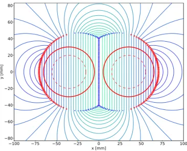
In order to avoid the too high density, and therefore the collision of the wires, the target magnetic field 𝐵0 and the number of the wires 𝑁 should be limited such that the maximum surface current density Eq. (2)does not exceed 𝐼max∕(𝐷wire +𝐺), where𝐼max is the maximum safe operating current at the given magnetic field, and𝐺is the minimum necessary gap to place the wires with sufficient accuracy (i.e. into individual grooves machined into aluminium formers, for example). If a higher magnetic field is required, the wires need re- alignment, for example using the following simple algorithm. Whenever two subsequent wires are closer than the minimum allowed distance, they are both snapped to their average position along the arc (𝑠1+ 𝑠2)∕2, displaced by±𝐷wire∕2in the normal direction.Fig. 3shows the resulting wire configuration and the magnetic field map for𝐵0= 0.7T and𝑁 = 54. The required wire current is𝐼0 = 753 A, which is 64%
of the short-sample critical current of two high-performance industrial superconducting wires, the Bruker F54-1.35-0.85 [14] and Supercon 54S43-54-1.3-0.85 [15], extrapolated to this low field value, as shown inFig. 4, at the same field and a temperature of 4.2 K. The peak field in a realistic 3D coil is not yet studied in this work. Using a pessimistic estimate of𝐵peak∕𝐵0= 2, the magnet current would still be only at 70%
of the critical current of the wires (seeFig. 4, dotted lines). Both wires have an insulated diameter of 0.9 mm and are therefore compatible with the wire layout presented above. The distance of the wires or pairs of wire is everywhere greater than about 1.4 mm.
The relative weight of the higher multipoles, sampled at 2/3 of the aperture, is shown inFig. 5, demonstrating the excellent field quality with all multipoles having a magnitude below 1 unit.
4. Summary and outlook
The presented realistic 2D wire arrangement creates an opposite- field septum field configuration with an accelerator-grade dipole field of ±0.7 T in two adjacent domains separated by about 4 mm. The wire configuration can be separated into two halves, which could be individually wound into aluminium formers with machined grooves for the wires, similarly to the canted cosine theta magnets, but with axial
Fig. 3. Field configuration of the opposite-field truncated cosine theta septum magnet with discrete wires (+ for positive, ∙ for negative currents). The thick solid red circles show 60 mm diameter apertures, the dashed circles show the sampling line for multipole analysis at 2/3 of the aperture. (For interpretation of the references to color in this figure legend, the reader is referred to the web version of this article.)
Fig. 4. Load lines of the magnet, and the critical current values of two industrial superconducting wires. Symbols show the values specified in the data sheets, the dashed and dash-dotted lines show a linear fit.
Fig. 5. Relative weights of the multipoles.
groves. The coil ends need a 3D design, and their effect on the quality of the integrated field must still be studied. The two coils can then be em- bedded in a larger support block, and epoxy-impregnated. The concept is easily scaleable to larger apertures without any complications. In case the large bulk supporting formers are made from conductive materials, the effect of eddy currents in fast-ramping rings must be studied.
3
D. Barna and M. Novák Nuclear Inst. and Methods in Physics Research, A 959 (2020) 163521
Declaration of competing interest
The authors declare that they have no known competing finan- cial interests or personal relationships that could have appeared to influence the work reported in this paper.
CRediT authorship contribution statement
Dániel Barna: Conceptualization, Methodology, Writing - origi- nal draft, Writing - review & editing, Visualization. Martin Novák:
Software, Visualization.
Acknowledgments
The research presented in this paper was supported by the Hun- garian National Research, Development and Innovation Office under grant #K124945. D.B. was supported by the János Bolyai Scholarship of the Hungarian Academy of Sciences. The authors are grateful to Elena Benedetto, Miro Atanasov and Jan Borburgh for their feedback and input to the presented work.
References
[1] S. Caspi, D. Arbelaez, L. Brouwer, S. Gourlay, S. Prestemon, B. Auchmann, Design of a canted-cosine-theta superconducting dipole magnet for future colliders, IEEE Trans. Appl. Supercond. 27 (4) (2017) 4001505, http://dx.doi.org/10.1109/
TASC.2016.2638458.
[2] L. Brouwer, S. Caspi, R. Hafalia, A. Hodgkinson, S. Prestemon, D. Robin, W.
Wan, Design of an achromatic superconducting magnet for a proton therapy gantry, IEEE Trans. Appl. Supercond. 27 (4) (2017) 4400106,http://dx.doi.org/
10.1109/TASC.2016.2628305.
[3] G. Montenero, B. Auchmann, D. Arbelaez, L. Brouwer, S. Caspi, R. Felder, F.
Lackner, S. Sanfilippo, S. Sidorov, D. Smekens, J.H. Swanson, Coil manufacturing process of the first 1-m-long canted–cosine–theta (CCT) model magnet at PSI, IEEE Trans. Appl. Supercond. 29 (5) (2019) 4002906,http://dx.doi.org/10.1109/
TASC.2019.2897326.
[4] G. Kirby, L. Gentini, J. Mazet, M. Mentink, F. Mangiarotti, J. Van Nugteren, J.S. Murtomaki, P. Hagen, F.O. Pincot, N. Bourcey, J.C. Perez, G. De Rijk, E.
Todesco, J. Rysti, Hi-Lumi LHC twin aperture orbit correctors 0.5 m model magnet development and cold test, IEEE Trans. Appl. Supercond. 28 (3) (2018) 4002205,http://dx.doi.org/10.1109/TASC.2017.2782683.
[5] K. Fan, I. Sakai, Y. Arakaki, Design method of a large aperture opposite-field septum magnet, in: Proceedings of EPAC2006, WEPLS071, Edinburgh, Scotland, 2006, URL https://accelconf.web.cern.ch/accelconf/e06/PAPERS/WEPLS071.
PDF.
[6] I. Sakai, K. Fan, Y. Arakaki, M. Tomizawa, Y. Saito, M. Uota, A. Nishikawa, R. Morigaki, A. Tokuchi, H. Mori, A. Kawasaki, Operation of the opposite- field septum magnet for the J-PARC main-ring injection, in: Proceedings of EPAC2006, TUPLS107, Edinburgh, Scotland, 2006, URL http://accelconf.web.
cern.ch/AccelConf/e06/PAPERS/TUPLS107.PDF.
[7] K. Sugita, Novel concept of truncated iron-yoked cosine theta magnets and design studies for FAIR septum magnets, IEEE Trans. Appl. Supercond. 22 (3) (2012) 4902204,http://dx.doi.org/10.1109/TASC.2011.2174953.
[8] K. Sugita, E. Fischer, P. Spiller, Truncated cosine theta magnet and the applica- tions, in: 9th International Particle Accelerator Conference, wepml036, JACoW Publishing, Geneva, Switzerland, Vancouver, 2018,http://dx.doi.org/10.18429/
JACoW-IPAC2018-WEPML036.
[9] D. Barna, High field septum magnet using a superconducting shield for the future circular collider, Phys. Rev. Accel. Beams 20 (4) (2017) 041002, http:
//dx.doi.org/10.1103/PhysRevAccelBeams.20.041002.
[10] D. Barna, M. Novák, K. Brunner, G. Kirby, B. Goddard, J. Borburgh, M.G.
Atanasov, A. Sanz Ull, E. Renner, W. Bartmann, M. Szakály, Conceptual design of a high-field septum magnet using a superconducting shield and a canted-cosine- theta magnet, Rev. Sci. Instrum. 90 (5) (2019) 053302,http://dx.doi.org/10.
1063/1.5096020.
[11] F. Krienen, D. Loomba, W. Meng, The truncated double cosine theta supercon- ducting septum magnet, Nucl. Instrum. Methods Phys. Res. A 283 (1989) 5–12, http://dx.doi.org/10.1016/0168-9002(89)91249-7.
[12] S. Bidon, D. Gerard, R. Guinand, M. Gyr, M. Sassowsky, E. Weisse, W. Weterings, A. Abramov, A. Ivanenko, E. Kolatcheva, O. Lapyguina, E. Ludmirsky, N. Mishina, P. Podlesny, A. Riabov, N. Tyurin, Steel septum magnets for the lhc beam injection and extraction, in: Proceedings of EPAC2002, 2002, pp. 2514–2516, URLhttp://accelconf.web.cern.ch/AccelConf/e02/PAPERS/MOPLE083.pdf.
[13] L. Badano, M. Benedikt, P.J. Bryant, M. Crescenti, P. Holy, A. Maier, M. Pullia, S. Reimoser, S. Rossi, G. Borri, P. Knaus, F. Gramatica, M. Pavlovic, L. Weisser, Proton-Ion Medical Machine Study - Part II, Tech. Rep. CERN PS/2000-007 (DR), CERN, Geneva, Switzerland, 2000, URLhttps://cds.cern.ch/record/449577/files/
ps-2000-007.pdf.
[14] Bruker, NbTi wire data sheet, URL https://www.bruker.com/fileadmin/user_
upload/8-PDF-Docs/BEST/DataSheets/NbTi_round.pdf.
[15] Supercon Inc., NbTi wire data sheet, URL http://www.supercon-wire.com/
content/nbti-superconducting-wires.
4