POWER SYSTEMS COMPARISON
H. A. Schulte Jr.*, J. H. Tarter"1", and R. G. Roble"
The Bendix Corporation, Southfield, Mich.
Abstract
The description, operating characteristics, advantages, dis- advantages, and problem areas of fuel cell systems, solar cell systems, and cryogenic chemical dynamic systems are presented.
System parameters are defined for power levels up to 5 kw and for space mission durations up to 1^ days. The limitations of each system are discussed and system characteristics compared.
Three Bacon-type fuel cell systems are analyzed: l) a partially integrated system in which the products of reaction are re- covered as crew water; 2) a nonintegrated hydrogen cooled system; and 3) a nonintegrated radiator cooled system. Two solar cell systems are discussed: a pure solar cell system de- signed for 100$ daylight operation and a solar cell-battery system designed for 60$ daylight operation. Two cryogenic chemical dynamic systems are analyzed: a completely integrated system using cryogenic hydrogen for power and all environmental cooling, and a partially integrated system using cryogenic hydrogen for power and partial environmental cooling.
Presented at the ARS Space Power Systems Conference, Santa Monica, Calif., September 25-28, 1962. The authors wish to thank the Bendix Research Laboratories for assistance in the preparation of and permission to publish this paper. A portion
of the work on this paper was done under the Bendix Aerospace Power Program, which is supported by the Red Bank, Bendix Products Aerospace, Utica, Bendix-Pacific, Bendix Systems, and Research Laboratories Divisions of The Bendix Corporation.
^Senior Engineer, Energy Conversion Systems Department, Research Laboratories Division.
"^Engineer, Energy Conversion Systems Department, Research Laboratories Division.
"Assistant Engineer, Energy Conversion Systems Department, Research Laboratories Division.
Nomenclature
ratio of hydrogen weight to total propellant weight useful fraction of propellants loaded into tank enthalpy change of hydrogen in accepting waste heat, Btu/lb
enthalpy change of oxygen in accepting waste heat, Btu/lh
specific heat ratio of working fluid
apparent molecular weight of working fluid, lb/rb-mole
useful power developed by power system, kw pressure ratio across prime mover
energy absorbed by propellants, kw
specific propellant consumption based on propellants expanding through prime mover, lb/kw-hr
specific propellant consumption based on propellants loaded into tank, lb/kw-hr
temperature of working fluid at prime mover inlet,°R time, hr
fixed weight, lb
specific weight of power system, lb/kw-hr
ratio of hydrogen tank weight to hydrogen weight ratio of oxygen tank weight to oxygen weight adiabatic efficiency of prime mover
electrical generator efficiency
I. Introduction
With the advent of manned space travel, the complexity, operating characteristics, and reliability of space vehicle subsystems have taken on new meaning. As a result, an increased interest has been shown in the subsystem analysis of nonpro- pulsive power supplies. Nonpropulsive power is required to supply electrical energy, in the form of either a.c. or d.c.
power, to electronic and associated equipment. In addition, mechanical energy may be required from the nonpropulsive power
supply for environment control, equipment cooling, and other mechanical functions. Also, the attitude control subsystem may be integrated in some nonpropulsive power supplies.
At present, the requirements established for nonpropulsive power supplies used in manned missions are for power levels up to 2 kw and for mission durations of 1^ days. The power supplies selected for these missions must be optimized with respect to weight and volume in order to have a minimum weight system. Since weight is of primary importance, consideration must be given to areas where weight economies may be achieved.
Such a savings may be realized by the integration of the non- propulsive power subsystem with other subsystems whenever such a possibility exists. System redundancy, although adding to system weight, provides backup protection in event of component failure or emergency operations, and should be considered when- ever possible in order to insure adequate reliability.
The criteria used for the comparison of nonpropulsive power supply subsystems in this paper are system weight, system volume, collector or radiator requirements, comparative ad- vantages and disadvantages, and problem areas. System charac- teristics such as type of power delivered, state of development, vehicle effects, maintenance factors, and control complexity as well as subsystem capabilities are also considered with respect to the power levels and mission durations involved.
II. System Analysis Fuel Cell Systems
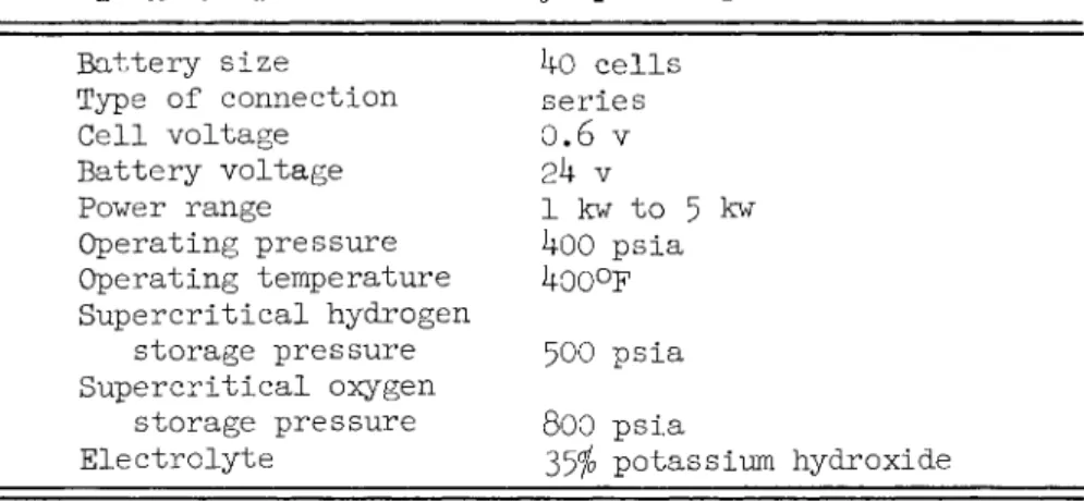
The fuel cell battery considered is a Bacon-type, hydrogen- oxygen fuel cell using 35$ potassium hydroxide solution as electrolyte. Operating characteristics of the fuel cell battery are shown in Table 1.
Table 1 Fuel Cell Battery Operating Characteristics Battery size ho cells
Type of connection series Cell voltage 0.6 v
Battery voltage 2k v
Power range 1 kw to 5 kw Operating pressure i|00 psia Operating temperature 400°F Supercritical hydrogen
storage pressure 500 psia Supercritical oxygen
storage pressure 8OO psia
Electrolyte 35^ potassium hydroxide A constant power level has Ъееп assumed to simplify this analysis. Specific space missions each have power profiles,
sometimes with extreme peaks of twice the design level. Since fuel cells, solar cells, and cryogenic chemical dynamic systems cannot vary their output over wide ranges, secondary batteries are generally used with the power supply to partially equalize the load. The batteries also provide backup power for emer- gency operation. Since battery requirements are extremely sensitive to specific mission power profiles, battery weights have not been included in the systems analyzed except for the 60/0 Daylight Solar Cell System. Battery weights included in this system supply constant power during the shadow portion of the mission.
Supercritical storage of hydrogen and oxygen has been speci- fied in this analysis for both the fuel cell systems and the cryogenic chemical dynamic systems. Both subcritical and super- critical storage were considered; however, subcritical storage was rejected due to expulsion problems, insulation problems, and auxiliary equipment weight.
Subcritical storage of hydrogen has a weight advantage up to approximately 50 psia tank pressure. Subcritical oxygen tanks are lighter up to approximately 500 psia. However, the inherent simplicity and reliability of supercritical storage systems indicate that supercritical storage at pressures exceeding operating pressures followed by subsequent pressure reduction presents fewer problem areas«,
The tankage weight estimates used in this analysis were taken from Ref. 1. These estimates are based on the use of spherical aluminum pressure vessels insulated with an evacuated multilayer insulation covered by a magnesium outer shell.
Fuel cell systems offer many advantages.2^ Efficiencies of 4 5 to 8570 &re attainable« Fuel is consumed in proportion to the load, providing optimum fuel economy. Fuel cell systems have high energy density, simple design, and low maintenance require- ments, Operation is silent and efficiency is maintained even under partial load*
Certain basic disadvantages of fuel cell systems must also be considered« Although the fuel cell itself is a demonstrable piece of hardware, very limited progress has been made in the assembly of a complete fuel cell system« Due to low individual cell voltage, many cells must be combined to form a battery.
Series connection in a battery requires electrolyte isolation, while parallel connection provides low voltage which reduces downstream component efficiency. The d.c. output of fuel cells is undesirable where a reasonably pure sine wave output is re- quired. Fuel cell electrode materials presently used are
sensitive to shock to the extent that normal shipping procedures are unsatisfactory.
Several particularly critical problem areas are peculiar to fuel cell systems: l) electrolyte interface control; 2) zero gravity mechanical problems; 3) electrical isolation of electrolyte circuit; k) regeneration of electrolyte vs water removal; 5) optimization of weight and volume.
The electrolyte interface problem is principally one of control of gas pressures and production of electrodes of uniform porosity« Sufficient pressure must be maintained to prevent electrode flooding by product water without blowing gas through the electrode into the electrolyte compartment. Phase separa- tion in a zero gravity environment is significant since a liquid electrolyte is used. Dilution of electrolyte with product water must be compensated for either by addition of solid or highly concentrated liquid electrolyte, or by water removal.
Either method presents problems, especially at zero gravity.
Weight and volume optimization are not particularly significant since minimum weight is not required for early flight hardware«
Three fuel cell systems are analyzed in the following.
1. Partially integrated fuel cell and crew water system The only integration possibility considered for fuel cell systems is the recovery of crew water from product water.
Integration of oxygen fuel with crew oxygen was investigated and rejected because no significant weight savings could be accomplished« However, provision can be made to use oxygen fuel for life sustenance in an emergency. Since the fuel cell
system produces more heat than can Ъе absorbed in the heat sink represented by the cryogenic fuel supply, integration with environmental heat load is not advantageous. Integration with attitude control subsystems would realize some weight savings but would contribute significantly to system complexity and
require excess heat input to maintain supercritical fuel tank pressures. In addition, attitude control requirements vary with individual missions, and, would be difficult to include
in a general comparative analysis.
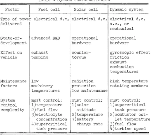
The schematic block diagram of the partially integrated system is shown in Fig« 1. Supercritical fuel storage is main- tained by controlled heat feedback. Blowers prevent stratifi- cation of fuels. Crew water might be recovered by an ion ex- change process or by distillation. The heat rejected by the fuel cell is principally absorbed in the heat sink represented by the cryogenic fuels. Excess heat is rejected in expendable excess product water and by space radiator. Only the most significant regulation and control devices are shown schemati- cally in this diagram.
This system is advantageous due to weight and volume economies achieved by eliminating separate crew water supply and tankage. However, inclusion of the crew water system in- creases complexity and zero gravity problems. The space radi- ator also presents problems of protection from meteoroid damage 2. Nonintegrated hydrogen cooled system
This system, shown in Fig. 2, eliminates the space radiator and rejects excess heat by using expendable cryogenic hydrogen.
Electrolyte regeneration is provided by evaporation of product water«
The advantages of this system are that the space radiator is eliminated with its attendant hazard of meteroid damage and that the system is less complex. Because the excess heat load is absorbed by expendable hydrogen, the weight and volume of this system are dictated mainly by the cooling requirement rather than power needs. The problem of phase separation at zero gravity is also present«
3« Nonintegrated radiator cooled system
This system, shown in Fig. 3j is a compromise between the systems previously discussed. Product water is expelled over- board in the downstream electrolyte circuit; the electrolyte is regenerated with solid potassium hydroxide or a highly concen- trated solution in the regenerator. Excess heat is dissipated
in a space radiator. The heat sink represented Ъу the cryo- genic fuels absorbs most of the heat rejected by the fuel cell battery. Here again, not all of the control mechanisms are
shown.
Advantages of this system are that it is the least complex and phase separation problems in zero gravity environment are virtually eliminated. However, this system requires the largest space radiator area and is slightly heavier and larger than the integrated system.
To provide greater system reliability, certain redundancy factors are included in the weight and volume analysis. A standby/emergency fuel cell with valves and controls is in- cluded in each system. An excess fuel weight of 15$ is carried in the supercritical storage tanks. Of this excess, 5$ is operationally available by exceeding the normal heat input to the tanks. The remaining 10$ excess oxygen is avail- able for crew sustenance in an emergency. Tankage subdivision would provide additional reliability with negligible weight penalty.
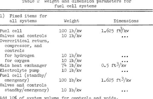
The weight and dimension parameters used in the fuel cell systems calculations are shown in Table 2. The values were chosen from information obtained in the literatures^>5 and from calculated material and heat balances performed on the systems.3
Table 2 Weight and dimension parameters for fuel cell systems
l) Fixed items for
all systems Weight Dimensions Fuel cell 100 lb/kw 1.625 fi?/kw
Valves and controls 10 lb/kw ...
Overcritical return, compressor, and controls
for hydrogen 10 lb/kw for oxygen 10 lb/kw
Main heat exchanger 7^ lb/kw 0.5 ft3/kw Electrolyte pump 10 lb/kw
Fuel cell (standby/
emergency) 100 lb/kw 1.625 ft3/kw Valves and controls
standby/emergency) 10 lb/kw
Add 10$ of system volume for controls and voids.
Table 2 ( c o n t ' d ) 2) Fixed items for
particular systems Weight Dimensions Integrated
Crew water purifier and
radiator-cooler 15 l"b/kw 0.5 ft^/kw
Area: 0.19 ft2/kw Supply tank 5 lb/kw 0.25 ft3/kw Expendable water heat
exchanger 50 lb/kw 0.5 ft3/kw Space radiator 28 lb/kw 0.5 ft3/kw
Area: З.Зб ft2/kw Subtract 22 lb/kw and O.75 ft3/kw for crew water system.
Nonintegrated Hydrogen Cooled
Expendable water heat
exchanger 50 lb/kw 0.5 ft3/kw Expendable hydrogen
heat exchanger 7^4- lb/kw 1.0 ft3/kw 3) Variable items for
all systems Cryogenic hydrogen
(fuel cell) 0.1б5 lb/kw-hr (0.0373 ft3/kw-hr) Cryogenic oxygen I.32 lb/kw-hr (O.OI85 ft3/kw-hrj Oxygen tankage Ref. 1 D = O.328 (kw-hr)V3
+0.13, ft - V = 1/6 TTD^ ftJ k) Variable items for
particular systems
Integrated , Hydrogen tankage Ref. 1 D = 0Л15 (kw-hr)1/3
Nonintegrated hydrogen cooled
+ O . I 3 , f t V = 1/6 тгБЗ, f tJ
Cryogenic hydrogen ~ (cooling) 0.80 lb/kw-hr (O.181 ft-Vkw-hr) ,
Hydrogen tankage Ref. 1 D = 0.7^5 (kw-hr) > 5 + 0.13* f t
V = 1/6 TTD3, f tJ
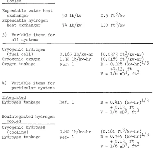
Table 2 (cont'd) k) Variable items for
particular systems
(cont'd) Weight Dimensions Nonintegrated radiator
cooled
Hydrogen tankage Ref . 1 D = 0.^-15 (kw-hr) l/З + 0.13 ft
V = l·/б TTD3, ft^
Potassium hydroxide
makeup O.683 lb/kw-hr ...
Electrolyte regenerator O.O75 lb/kw-hr O.OO67 ft3/kw-hr 5) Space radiator
requirements
Integrated ... 3.55ft2/kw
Nonintegrated radiator
cooled ... 5.0 ft2/kw
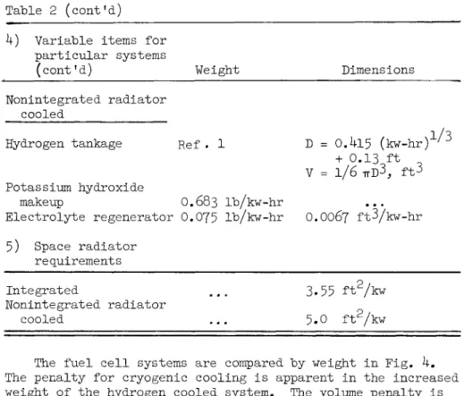
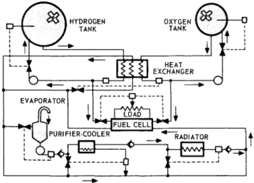
The fuel cell systems are compared by weight in Fig. hm
The penalty for cryogenic cooling is apparent in the increased weight of the hydrogen cooled system. The volume penalty is even greater. System weights for the integrated and the non- integrated radiator cooled systems are quite similar, especially for missions up to 100 hr. Selection of a system for a specific mission would be based on other factors. Selection of the hydrogen cooled system might be possible for a mission where it is desired to eliminate a space radiator and keep the entire system on board.
Solar Cell Systems
Solar cells are photovoltaic solar energy converters, generally semiconductor devices of the diffused junction type.
They are small(usually 1 x 2 cm) and are characterized by
relatively low output voltages and low short circuit capability.
As a result, it is necessary to combine thousands of cells to meet the various power requirements needed in space vehicle application. The power output per cell is determined from cell
characteristic curves relating the output current to output voltage for various temperature levels.° Since the voltage produced by a single solar cell is low, several cells must be connected in series to obtain the desired voltage. Such a con- nection, called a "string," is connected in parallel with
several other strings to ohtain the required power.
Batteries are used to provide the necessary operating power when incident solar energy is absent. The solar cell array must provide sufficient voltage to assure charging rates com- patible with system requirements. The advantages and disad- vantages of solar cells are summarized in Table 3-
Table 3 Solar cell characteristics
Advantages Disadvantages
1)
2)
3)
h)
5)
6)
7)
Light in weight, simple and reliable
Long life expectancy
Converts solar energy
directly to electrical power with no moving parts or intermediate heat cycle Can be connected by shingling to produce high output per unit area
Can be gridded to cut down the resistance of the "P"
layer and improve conversion efficiency
Cell impedance is low
Transient response time is low (10 |jisec rise and 20 jjLsec decay)
i )
2)
3)
h)
5)
6)
7)
Power output decreases as cell temperature increases (-0.6$>/°C between -10 and +170°C) requiring tempera- ture control
Collectors must be operated with a fixed load or at a
constant voltage (for charging batteries) Conversion efficiency in- creases with increasing level of illumination
Cells should be current- matched when connected in
series for increased voltage output, and should be
voltage matched when con- nected in parallel for increased current output Heat must be dissipated, usually by radiation
Humidity sensitive at elevated temperature (must be encapsulated)
Degradation can occur in a high radiation energy environment
Tahle 3 (cont'd) Advantages
8) Generated current varies linearly with incident light intensity
9) No degradation of per- formance over a wide range of pressure
Disadvantages 8) Solar cell systems are
relatively high in cost ($50 to $500 per watt at present)
The most economical use of solar cells is realized if the array or arrays are all oriented with respect to the sun.
Orientation need not he precise, since the effect of slight misalignment of the cells does not result in large power losses.
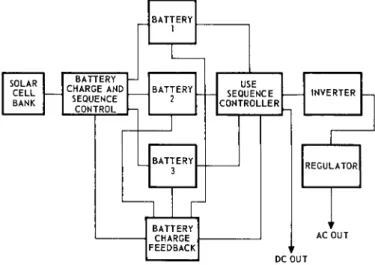
Energy must he stored for operation in the earth's or moonTs shadow; this energy will he reflected as battery charging power requirements during daylight operation. A 60$ daylight solar cell system utilizing a constant voltage charging technique is shown in Fig. 5. The 100$ daylight solar cell system would he essentially the same except for the deletion of the batteries.
Each battery shown in the power system is charged from the solar array as required through its own battery charging regu- lator system.
Each of the three systems operates independently and means are provided in the sequence controlling system to switch from one battery system to another.
Two systems are considered for comparative purposes: a 100$ daylight system fully illuminated throughout the operating period, and a 60$ daylight system for a 100-min earth orbit
illuminated for 60 min. The systems chosen will represent boundaries between which systems of more typical mission dura- tion will lie.
In order to compare the system parameters of the three power supply systems discussed in this paper it was necessary to establish arbitrary mission requirements for the solar cell system because of its dependence on solar energy. This was not necessary for the fuel cell or cryogenic chemical dynamic systems.
The system weights, collector area, and system volumes for the two systems were calculated from design parameters in the
literature/ They are shown vs the systems weight and volume comparison at the 1 kw power level only in Figs. 10 and 12.
The parametric analysis was based on actual hardware extrapolated to comply with the power levels specified for the other two
systems.
Included in the weights and volumes of the solar cell system are the inverters, regulators, batteries, and associated equip- ment. The size of the related equipment is dependent on the power level involved and 15-20 lb/kw can be realized for the
control system. An energy density of 30 w-hr/lb can be expected from a silver zinc secondary battery and a panel and cell weight of 1.0 -1.5 lb/ft can be expected depending upon the size of the radiation protective glass cover. For purposes of this paper a 1 x 2 cm solar cell realizing 0.022 w/cell was used for
calculation purposes.
Because of the nature of the generality involved in the defined missions, no particular system characteristics will be presented.
At present, solar cell systems are the only secondary power systems which can be considered proven flight hardware. The increased demands for higher power levels will rule out the use of massive solar cell systems, because of the size, cost, fabri- cation, and packagability problem involved with high power
systems; but, for now, solar cells are the only reliable devices.
Improvement of efficiency, refinement of temperature control, enhancement of radiation resistance, and development of tech- niques for producing large area, more flexible cells, will make them sufficiently competitive to occupy a portion of the space power spectrum for some time.
Cryogenic Chemical Dynamic Systems
In the chemical dynamic power system, a fuel and oxidizer are reacted to produce a high temperature gas, which is then expanded through a prime mover driving an electrical alternator to produce the required power. For the low duration missions and power levels, a monopropellant, such as hydrogen peroxide or hydrazine may be used to produce the hot gas. However, once an appreciable total power requirement is reached, a bipropellant reaction must be used. Liquid hydrogen as the fuel and liquid oxygen as the oxidizer have received the most attention.
The hydrogen-oxygen combustion reaction possesses a number of characteristics which make it quite desirable for this application. An extremely wide range of temperatures can be obtained by varying the hydrogen to oxygen ratio. Since the
combustion products are rich in hydrogen, they have a low molecular weight, producing a low specific propellant consump- tion for a given temperature. The reducing nature of the com- bustion gases is also advantageous from a materials standpoint,
The prime mover may be either a turbine or a positive dis- placement device. Turbines have the advantage of fewer moving parts and comparative simplicity. In addition, turbines can use a low inlet pressure more effectively than a piston engine, This is a consequence of the higher mechanical losses in the positive displacement machine. An advantage of the positive displacement engine is the tendency to operate more efficiently off the design point than a turbine.
Dynamic power systems possess a number of advantages. One of these is the great flexibility in the type of power output which can be obtained. Delivery of a.c. or d.c. electrical power, hydraulic, or even mechanical power singly or simul- taneously presents no significant problems. If a.c. power is required, the sine wave form can be quite pure. The generation of a sine wave by alternators instead of converter-inverters makes the chance of harmonic interference generation more remote.
This can be a particularly difficult problem where large amounts of statically inverted power are required,
A dynamic system can be constructed to operate reliably with state of the art components. Cooling problems in this type of system are not critical.
One of the major disadvantages of the cryogenic chemical dynamic system is the storage problem created by cryogenic pro- pellants. In addition, the low density of hydrogen tends to produce large volumes. Dynamic systems have rotating parts which require lubrication and which disturb vehicle attitude through reactive torques and gyroscopic moments. In addition, exhaust products must be rejected without creating further attitude disturbances.
Two cryogenic chemical dynamic systems are next analyzed.^
1. Cryogenic chemical dynamic power system integrated with vehicle cooling system
The hydrogen used to power a cryogenic chemical dynamic power system is at a low temperature and has a high specific heat. It thus represents a heat sink of considerable magnitude.
Almost all the energy produced by the power system in a space vehicle will appear as waste heat, which must be dissipated if
vehicle temperatures are to he maintained within proper limits.
If the vehicle is manned, there will he an additional metabolic cooling load. When faced with a cooling problem and possessing a heat sink, it is obvious to attempt to absorb the waste heat with the cryogenic propellants.
A schematic of such a power system is shown in Fig. 6. An intermediate heat transfer fluid is used to collect the waste heat from various points within the vehicle and convey it to heat exchangers where it is transferred to the hydrogen. After absorbing a certain portion of the waste heat, the warmed
hydrogen is used to supply the energy required to maintain supercritical conditions within the tanks before absorbing the remainder of the waste heat.
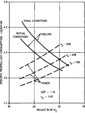
If the cryogenic propellants supplying the space vehicle power system are used to absorb waste heat, propellant flows must be balanced so that the requirements of both the cooling system and the power system are simultaneously satisfied. The point of balance defining the ratio of hydrogen to oxygen and the specific propellant consumption may be determined by
plotting the characteristics of the power system and the cooling system on the same set of coordinates.
Such a plot is shown in Fig. 9 and has been taken from Ref. 1. This curve is based on hydrogen and oxygen tempera- tures of 260°F at the inlet of the combustor, a ratio of heat absorbed to useful power produced equal to 1.18, a pressure ratio of 100, and an electrical alternator efficiency of 85/0.
The curves on Fig. 7 have been plotted from:
3413
s= = ггн (1)
„ - I
k1(1544)
\ ' p \ k - 1/(778M) i P
and i
= ._Ql / 3413 \
~ [ p f A h + ( l - f ) A h ( Z )
\ h ° /
Equation (l) defines specific propellant consumption in terms of the power requirement, Eq. (2) in terms of the cooling requirement. The derivation of these equations may be found in Ref. 1.
The weight of a power system with integrated cooling may be obtained from
w f
W
s =S
t[
1 +f w
h +d - f ) w
o] + — (3)
The specific propellant consumption S^ is obtained from
s
t
=F (4)
For supercritical storage, about 85 to 90$ of "the propellants loaded into the tank can be expelled without resorting to
excessive heat inputs. F = O.85 has been used in this analysis.
From Fig. 7j for a prime mover efficiency of oOfoj S = 2.53 to 3.73 lb/kw-hr and F = 0.725 to O.8OO. Using average values of S and F, values of w^ and w from Ref. 1, F = O.85 and Wf/P = 100 lb/kw at 1 kw and 5 kw> the specific weights of a power system integrated with the cooling system have been cal- culated and plotted in Fig. 8. The fixed weight values include provision for two sets of prime movers, alternators, and con- trols , but do not include cooling system weight.
The propellant volume of this system will be 0.590 ft^/kw- hr. The system volumes may be calculated on the basis of 1 ft^/
kw at 1 kw and O.75 ft3/kw at 5 kw.
2. Cryogenic chemical dynamic power system partially integrated with vehicle cooling system
As can be seen from the previous discussion, a high per- centage of the propellant weight is hydrogen. This leads to large system volumes and tank weights. In addition, the
temperature of the working fluid is low, giving a poor specific propellant consumption. Assuming a reasonable extrapolation of the state of the art, turbine temperatures of l800°F can be used. This requires that 53$ hy weight of the propellants be hydrogen,
Substitution of values into Eq. (l) gives S = 2.08 lb/kw-hr for У] = О.бО. Substitution of proper values into Eq. (2) gives a range of value of the Q/P ratio of 0.6l to 0.7^. Thus 26 to 39$ of the waste heat must be disposed of in some other way, presumably by being radiated to space.
Figure 9 shows the schematic of a power system partially integrated with the vehicle cooling system. Except for the radiator this is similar to the schematic of the system pre- viously shown.
Weights for the partially integrated system have Ъееп calcu- lated in a manner similar to that described previously, with the addition of 20 ГЬ of radiator per kw of energy rejected to space.
These weights have also been plotted in Fig. 8.
The volume of the propellants for the partially integrated system is 0.3^-0 ft-^/kw-hr. This is a considerable improvement over the volume for the system with completely integrated cooling.
The power system with partially integrated cooling has con- siderably less weight and volume than the power system with completely integrated cooling. This is a consequence of the additional hydrogen required for cooling in the completely
integrated system.
III. Systems Comparison Weight Comparison
The seven space power systems analyzed are compared on a weight basis at 1 kw power level in Fig. 10. Except possibly for very short, low level missions, the 100$ Daylight Solar Cell System has the least weight of any system. The 60$ Day- light System becomes competitive beyond 150 kw-hr. The low weight and long duration features of solar cell systems are thus evident. However, the solar cell's deceptive disadvantages of high radiator area (shown in Fig. lh) and extremely high cost must be mentioned. Neither of these disadvantages apply to fuel cell systems or chemical dynamic systems.
Tradeoffs between fuel cell and chemical dynamic systems occur from 100 kw-hr to 800 kw-hr. Of particular interest is the tradeoff between the partially integrated dynamic and partially integrated fuel cell systems at 250 kw-hr since these
systems are lightest in each category. Solar cell systems operating in earth orbits at low power levels and for short durations are heavier than the other systems, yet they are still in use because of their advanced state of development and in- herent reliability«,
The weight comparison at 5 lw is shown in Fig. 11. Solar cell systems are not included because their feasibility is speculative at this power level.
The fixed weight penalty of fuel cell systems is evident at higher power levels. Even the heavier completely integrated dynamic system is competitive to 600 kw-hr and the partially
integrated system to 1500 kw-hr. Dynamic system specific weight is inversely proportional to power level whereas fuel cell system weight is directly proportional. This is because fuel weight is predominant in dynamic systems while fixed weight is predominant in fuel cell systems.
Volume Comparison
The volume comparison at the 1 kw power level is shown in Fig. 12. The advantage of fuel cell systems, especially of the partially integrated or nonintegrated radiator cooled type, is
quite clear. At low power levels and long durations the volume penalty suffered by the dynamic systems using low density hydrogen at a high fuel ratio is a significant problem. Low kw-hr profiles can provide the difference in volume, but the penalty soon becomes excessive.
At higher power levels dynamic systems are more competitive as shown in Fig. 13« Here the tradeoff in volume occurs at about 100 kw-hr for the lighter systems. At lower power levels and for shorter duration missions the volume disadvantage is not critical because a vehicle can usually accommodate the system. However, when volume becomes excessive, tank diameter may exceed vehicle diameter, necessitating tank subdivision and additional volume penalty. There is also an interaction between volume penalty and weight penalty resulting in excessive vehicle structural requirements.
Other Comparisons
The comparison of solar collector area and space radiator area is seen in Fig. 1^-. The disadvantage in solar cell systems of requiring large panel arrays, especially as power level increases, is obvious. Mechanical orientation of these panels poses another problem and imposes an additional load on the electrical system. Structural problems of large-area arrays is also critical. Since neither the nonintegrated hydrogen cooled fuel cell nor completely integrated dynamic systems have space radiators, they do not appear in this com- parison. While the partially integrated dynamic system has a
space radiator, it is part of the vehicle cooling system;
hence, it is not included in this comparison.
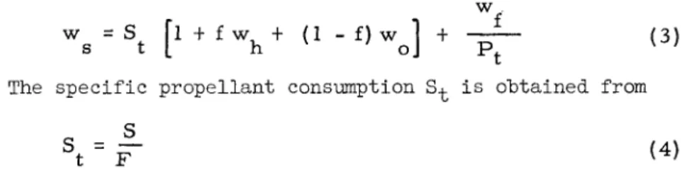
A systems characteristics comparison is shown in Table 4, giving some of the engineering factors on which power system selection can be based. Since no single system possesses all the advantages or is free of all disadvantages, the selection is not clear-cut. As in most engineering judgments of this type, analysis must be made with specific mission objectives in mind.
Table k System characteristics Factor
Type of powei delivered State-of- development Effect on vehicle
Maintenance factors System control complexity
Fuel cell r electrical d.c.
advanced R&D exhaust pumping
low machinery
temperatures must control:
l)temperature 2)fuel flow 3)electrolyte
concentration h)supercritical
tank pressure
Solar cell electrical d.c.
operational hardware counter- torque
radiation protection low maintenance must control:
l)solar attitude 2)temperature 3)battery
charge rate
Dynamic system electrical d.c.
a.c, or mechanical operational hardware
gyroscopic effect friction
exhaust combustion temperatures high temperature rotating members must control:
l)supercritical tank pressure 2)combustor out-
let temperature 3)fuel flow k)turbine speed Power level and mission duration capabilities of the system can be compared. Fuel cell systems utilizing the Bacon-type cell will be operational at the present rate of development in the power range of 1 kw to 10 kw and for missions of 1 to ik days. Development time will probably be 3 to 5 yr. Cryogenic chemical dynamic systems are operational in the power range of 0.5 kw to over 100 kw and for mission durations of minutes to ik days depending on power level. Hence, both of these systems span the scope of this analysis. Solar cell systems, however, are usually limited to 0.5 kw, can be designed to 1 kw, and are speculative to 2 kw due to collector array area and high cost.
Their mission duration is extensive, being limited only by deterioration due to gamma radiation, meteorite impact, and battery life.
IV. Conclusions
Although specific space power systems must be selected on the basis of individual mission specifications, noncategorical system selection can be made on the basis of this comparative
analysis. Hence, the partially integrated fuel cell system and the partially integrated dynamic system are optimal in their respective types of system. The solar cell systems are optimal in weight, degree of development, and reliability; however, they lose their competitive position due to volume, collector area, and cost, as power level increases. Tradeoffs can be established based on weight, volume, and other comparable factors.
Hence, this comparative analysis can aid in the selection of power supplies for specific space missions. However, it must be emphasized that an analysis can not be substituted for sound engineering judgment in evaluating advantages and disad- vantages of space power systems for specific missions.
References
^-McArthur, G.L. and Tarter, J.H., "Study of integration of of cryogenic dynamic power system with vehicle cooling system,"
ARS Preprint 2517-62 (September 1962).
2Liebhafsky, H.A. and Grubb, W.T., Jr., "The fuel cell in space," ARS J. 31, II83-H9O (l96l).
-Л/oltz, S.E. and Kerr, D.L., "Fuel cells for space power systems," Soc. Automot. Engrs. Preprint 469C (January 8-12,1962),
I3urriss, W.L. and Mason, J.L., "An integrated cryogenic system for spacecraft power, thrust, and cooling," Am. Soc.
Mech. Engrs. Paper 61-AV-39 (March 12-l6, 196l).
^Holden, P.C. and Stump, F.C., "Optimized condenser- radiator for space applications," Am. Soc. Mech. Engrs. Paper 6O-AV-I6 (June 5-9, I960).
^vans, W.H., Mann, A.E., Weiman, I., and Wright, W.V.,
"Solar panel design considerations," Progress in Astronautics and Rocketry: Space Power Systems (Academic Press, New York, 1961), vol. k, pp. 79-110.
7
'Menetrey, W.R., Energy Conversion Systems Reference Hand- book, Wright Air Development Division TR 6O-699, Vol. IX (i960).
o
°Traynelis, K.A., Jennings, A.J., and Hall, G.M., "Study of integrated cryogenic fueled power generating and environmental control systems, Vol. I - summary report," Aeronautical Systems Division TR 61-327 (1961).
HYDROGEN
TANK OXYGEN TANK
S^
EXCHANGER HEAT1 I r&i !
^ ^ ] F U E L C E L L p ^
I
PURIFIER-COOLER RADIATOR
Fig, 1 Integrated fuel cell and crew water system
EXPENDABLE HYDROGEN HEAT EXCHANGER
? 1
Г Ч О А Р Н
L» * + | F U E L CELL
Fig, 2 Nonintegrated hydrogen cooled fuel cell system
OXYGEN TANK
HEAT EXCHANGER
I rtfcri щ
*^tJFUEL C E T L } ^ ^
ELECTROLYTE REGENERATOR
RADIATOR
EXPENDABLE ELECTROLYTE
Fig. 3 Nonintegrated radiation cooled fuel cell system
100 1 r „
1
1 K*
{>
^
^s
^
1 1 1
b>
4
vj ys
>1
* 11
4-
^Lr^ г^
4 > J ^ ^ . ^MV ^^"
l^o-
* :
* ^ f c ^
^ , % ^
1 1 1 1 1 1 1 1 1 1 1 1 1 1 1 1 1 1 1 1 1 1 1 1 1 1
s„ /^
^^
^J
PARTIALLY INTEGRATED.
NON-INTEGRATED 1 I HYDROGEN COOLED —— — ~ГТ рАП1 АТПС m m РП — — _ _ J L
s
ч
1 «
Nü
\\
41 Гг^-
1 0 0 KILOWATT-HOURS 1 0°° 10,000
Fig. k Fuel cell systems weights
SOLAR CELL BANK
BATTERY 1—I CHARGE AND
SEQUENCE CONTROL
BATTERY 1
BATTERY 2
BATTERY 3
SEQUENCE USE CONTROLLER
BATTERY
r
CHARGE FEEDBACK
INVERTER
REGULATOR
AC OUT DC OUT
Fig, 5 Solar c e l l system with hattery pack
METABOLIC LOAD
fvwvwf
,s«
I |VWVW>|—Ir**~o—
SUPERCRITICAL
i
ELECTRONIC LOAD
COOLANT LOOP
Jvwwwl- Jvwvwvl
ELECTRICAL AND HYDRAUUCLOAD
f w w w t
- * t * -
ALTERNATOR AND LOAD •
-*!«-
S43
COMBUSTORSUPERCRITICAL 02 TANK
Fig. 6 Hydrogen-Oxygen dynamic system with integrated cooling system
W E I G H T % O F H ,
Fig. 7 Matching of propellant consumptions
k ^
* 4
>5 КУ
1
* 4 V 1
N 4s
Г""* """"
1 KW
POW SYST INTE
:R A EMS GRA ND PA T E
»0 SY IN"
CC RT WE ST E
)0 IA :R A EMS GRA
LIN( 1
LLY
ND COOLIN COMPLETE
Ú N
TED"j)s^
G LY
100 300 KILOWATT-HOURS
Fig. 8 Weights of cryogenic dynamic power systems
METABOLIC LOAD
RADIATION TO SPACE *
£
JWWWVl— f W V W w f - i->ц-
т>
О — - *
SUPERCRITICAL H2 TANK
ELECTRONIC
LOAD ELECTRICAL AND HYDRAULIC LOAD J V W W W f
~s
TURBINE
Fig. 9 Hydrogen-Oxygen dynamic system with partially integrated cooling system
uu-
1-
♦ % ,
^ Ч
100%
SOL
w*a
'*
4
DA
* R C
L _
vj
^^ *
\
YLI
L EL
^
»ш
^
N
GH L
L
4
T,
L
Y'
l4
4 n
NON-INT / Г HYDROG
X"
\
EGRA EN CC
» ^ ^ 1
4. N
N
TED OLE
>
\
D
Г?
N
M i l 1 I 1 1 1
I I ' I '
- FUEL C E L L SYSTEMS CRYOGENIC DYNAMIC
SYSTEMS " "
SOL
60%
' SOL
AR CELL S Y S T E M S — —
/IN" CO
/ o r / /
> y
f"-■
T * * ^
DAYLIGHT AR CELL
Ц
MPLE rEGR/
NAMIC
P/
' D\
TEL ГГЕС Y
)
^RTIALLY TEGRATE ГМАШГ D~
1 1 1 1
^NON-INTEGRATED RADIATOR COOLED
\ IN TEG RA TE D
1000 10,000
KILOWATT-HOURS
Fig. 10 Systems weight comparison at 1 kw power level
uu-
1 -
4
PA IN DY
*•*■
чч
COMPLETELY ^ ^
INTEGRATED л
K
*
r
RT1ALL Y / ^
TEGRATED Y NAMIC
_[[
Л.
J* —
I I I 1 I I I ' ' 1 '
FUEL CELL SYSTEMS — CRYOGENIC DYNAMIC
4
T ^ ^ -NON-INTEGRATED T~
HYDROGEN COOLEDr NON-INTEGRATED t~
INTEGRATED 1 1 ] _ L
100 1000
KILOWATT-HOURS
Fig, 11 Systems weight comparison at 5 kw power level
10,000
KILOWATT-HOURS
Fig. 12 Systems volume comparison at 1 kw power level
10,000
KILOWATT-HOURS 10,000
Fig. 13 Systems volume comparison at 5 kw power level
UUU 1
500
50
5
1*
S COL DLA
-EC TOF S
RA
1 R> Nf
>PACE
60% DAYLIGHT SOLAR CELL
100% DAYLIGHT SOLA" <~FI 1
DN-INTEGRATED .
^DIATOR COOLED
sC NT EG U T ED FUEL l_tl_L -
0.5 1.0 POWER LEVEL, KW
5.0 10.0
Fig. lh Collector-radiator area comparison