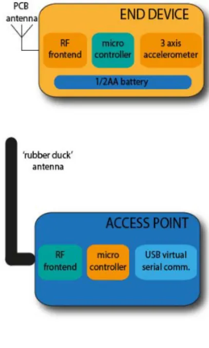
Figure 1. System overview
Miniature wireless sensor design for behavioral analysis on free-roaming laboratory animals
Gergő Sántha*/**, Gyula Hermann**
* Diagnosticum Zrt., Budapest, Hungary
** Óbuda University, Budapest, Hungary sgergo@yahoo.com, hermann.gyula@nik.uni-obuda.hu
Abstract—In this paper, a miniature wireless sensor system based on a tri-axis accelerometer is proposed. The sensor system consists of an End Device (ED) and an Access Point (AP). The ED acquires and transmits the accelerometer data operating in the license free 2.4 GHz ISM band. The AP receives and forwards the data packets to the PC through USB virtual serial connection. The small size of the ED allows the device to be mounted on a collar thus the accelerometric data from free-roaming laboratory animals can be observed and processed.
I. INTRODUCTION
Activity recognition of the laboratory animals has a long tradition in pharmaceutical research where the primary method for inspecting animal behavior is visual observation and analysis. Vision-based recognition systems typically use single color cameras and sophisticated algorithms to extract important image sequences from the recorded material. A disadvantage of these camera systems is that they can’t operate in dark and they have trouble to record fast, periodic movements like body tremor[1][2].
The rapid development of the MEMS (Micro Electrical Mechanical System) technology, made accelerometer- equipped devices available in daily life, for example the popular computer game controller, Nintendo Wiimote [3].
These wireless devices provide new ways for interacting with computers or other devices.
In the past years, the sensor technology offers several small accelerometer sensors to put into everyday devices and these sensors are readily available from the main electronic component distributors.
Similarly to modern accelerometric human-machine interfaces (Nintendo Wiimote), accelerometers can be used to detect and classify animal movements and behaviour. These accelerometric sensors are small enough to enable to construct such miniature circuits which don’t hinder the laboratory animals in their movement.
II. SYSTEM DESCRIPTION
A prototype sensor system has been created to collect tri-axial accelerometric data(Fig.1). The sensor system consists of a miniature, collar-mountable accelerometric sensing End Device (ED) and an USB bus powered Access Point (AP).
A. The LIS3LV02DL accelerometric sensor
The ED uses a commercial, three-axes digital accelerometer, the LIS3LV02DL from ST Microelectronics, to measure and collect accelerometric data in the range of ±2g or ±6g (selectable) and has a maximum bandwidth of 640 Hz. The IC incorporates a sensing element and a digital interface (SPI/I2C). The acceleration data may be accessed through the I2C/SPI interface. The maximum SPI clock frequency is 8 MHz.
The device has a selectable resolution of 12/16 bits.
The LIS3LV02DL features a Data-Ready signal (RDY) which indicates when a new set of measured acceleration data is available thus simplifying synchronization in digital system employing the device itself.
The device has 31 registers which are used to control its behavior and to retrieve acceleration data. In the ED, the configuration of the registers is done by using the standard, 4-wire SPI interface.
The sensor comes in a small, surface mounted LGA-16 package.
SISY 2012 • 2012 IEEE 10th Jubilee International Symposium on Intelligent Systems and Informatics • September 20-22, 2012, Subotica, Serbia
– 239 – 978-1-4673-4750-1/12/$31.00 ©2012 IEEE
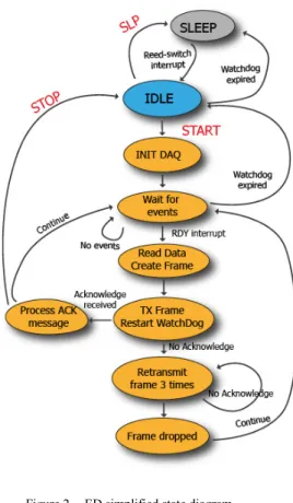
Figure 2 ED simplified state diagram (Radio commands in red uppercase) B. The nRF24L01+ based RF frontend
The ED has a 2.4 GHz frequency radio frontend with printed circuit antenna. The RF frontend is based on a highly integrated, ultra low power 2Mbps RF transceiver IC, nRF24L01+ from Nordic Semiconductor. The chip has ultra low power consumption: transmission at 0 dBm draws 11.3 mA whilst receiving consumes 13 mA at 2Mbps data rate (typical values).When powered down the chip draws 900 nA.
The chip can be programmed by its 24 registers using the 4-wire SPI protocol.
The nRF24L01+ is equipped with an embedded baseband protocol engine (Enhanced ShockBurst™) suitable for ultra low power wireless applications.
The Enhanced ShockBurst™ offers a set of functionality which helps keeping the wireless connection robust and reliable. Enhanced ShockBurst™ is a packet based data link layer that features automatic packet assembly and timing, automatic acknowledgement and retransmissions of packets. These hardware implemented features help to keep the host side software complexity low thus speeding up the development time. The ED uses the Auto-Acknowledge and Auto-Retransmission (ART) functionality. If the Auto-Acknowledge functionality is on, the transmitter side enters into receive mode immediately after transmitting out a packet. In the meantime, the receiver part, after successful reception of the packet changes to transmission mode, sending out an acknowledgment packet to the transmitter waiting for the acknowledgment. Receiving the acknowledment packet lets the transmitter side know that the transmission was successful.
If the transmission failed and the Auto-Retransmission (ART) functionality is on, the device retries to transmit the packet. The number of retries and the delay interval between two consecutive retransmissions can be configured writing the registers of the nRF24L01+.
In the ED we implemented the ‘meander’ antenna design. The meander antenna or meander pattern, is an antenna with the wire folded back and forth where resonance is found in a much more compact structure than can otherwise be obtained. The meander antenna has a fairly omnidirectional radiation pattern, good efficiency, and is very simple. It is also reasonably compact which is an important factor in space-constrained applications.[4][5][6][7][8].
The AP is built around the rubber duck antenna design.
C. The ultra low power microcontrollers, the MSP430F2013 and the MSP430F2211
In the ED, the interchip communication between the sensor and the RF frontend is controlled by an ultra-low power, 16-bit microcontroller, namely the MSP430F2013, from Texas Instruments. The transmitted data is received by the Access Point (AP) which uses a higher pin count microcontroller, the MSP430F2211 from Texas Instruments, is used to read out the received data packets and forward them to the PC, via USB virtual serial communication.
The MSP430 family is an industry leading ultra-low power microcontroller family. The MSP430 incorporates a 16-bit RISC CPU, peripherals, and a flexible clock system that interconnect using a von-Neumann common memory
address bus and memory data bus. The key features in power consumption are:
• 0.1 μA RAM retention
• 0.8 μA real-time clock mode
• 250 μA/MIPS active
The clock system is designed specifically for battery- powered applications. A low-frequency auxiliary clock is driven directly from a common 32-kHz watch crystal. The auxiliary clock can be used for a background real-time clock self wake-up function. An integrated high-speed digitally controlled oscillator (DCO) can source the master clock used by the CPU and high-speed peripherals. By design, the DCO is active and stable in less than 2 μs at 1 MHz. MSP430-based solutions effectively use the high- performance 16-bit RISC CPU in very short bursts[8].
In both the ED and AP, only the DCO is used, the low- frequency auxiliary clock is not utilized thus saving PCB real estate.
The ED is supplied by a 1/2AA sized Li-ion battery which is small enough to be holstered in the animal’s collar.
The AP is USB bus powered and is supplied by the host computer via an USB-A connector.
III. FIRMWARE IMPLENTATION
In the ED, ultra low power consumption was paramount. Thus, when the system is in the idle state it enters into low power mode after a period of inactivity. To G. Sántha and Gy. Hermann • Miniature Wireless Sensor Design for Behavioral Analysis on Free-Roaming Laboratory Animals
– 240 –
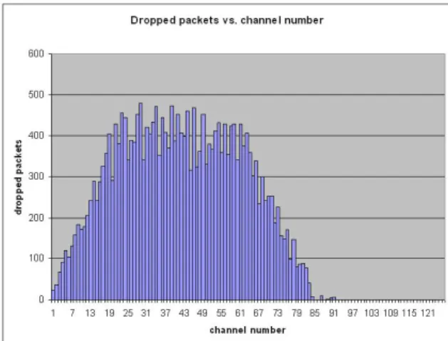
Figure 3 Dropped packets versus channel number (2400-2525 MHz, channel bandwidth 1 MHz)
exit from low power mode the device has to be awakened by a magnetic rod which closes a Reed-switch, generating a rising edge interrupt. The microcontroller then powers up the sensor, wakes up the RF transceiver and enters into RX state, listening to radio commands from the AP. The accelerometer has three, 16-bit sigma-delta converter which has selectable output data rates. Based on the selected data rate, the sensor can be configured to indicate when a new set of measured acceleration data is available, by generating a low-to-high signal on its RDY pad. This signal interrupts the microcontroller which then reads out the pending axis data using the SPI bus. Reading out all the axis data deasserts the RDY pin indicating that there is no pending data in the axis result registers. Next, the axis data is organized into data frames containing a header, a command ID, the actual data, a time-stamp and a CRC value. Finally, the data frame is uploaded into the transceiver IC’s transmit FIFO and is transmitted.
Communication with the RF chip is via the SPI bus. The RF protocol uses the nRF24L01+ chips’ hardware Auto- Retransmission (ART) and Auto-Acknowledge functionality, making the wireless connection more robust.
The AP receives the data frames and checks the frame integrity by verifying the CRC. After a successful CRC check the AP checks the time-stamp to detect missing frames. There might be lost frames depending on the interference of other operating devices in the same frequency range. The interference can be reduced by choosing a frequency band outside of the Wi-Fi range.
After the successful frame integrity and time-stamp tests the frame is forwarded to the PC using the UART protocol.
On both devices the firmware runs in a superloop architecture (Fig.2). To handle the different tasks a state machine has been implemented. Since the tasks follow the same schedule there was no need to implement prioritization.
IV. RESULTS
Several tests have been made to verify the system performance especially the robustness of the wireless connection. The selected output data rate was 40 sample per second. In the test there were 30000 frames sent at 40 frames per second on one channel and received by the
receiver. The dropped frames had been counted and the channel number was incremented. Since the 2.4 GHz ISM range is overcrowded there were dropped frames up to the 2% of all sent frames. The frame drop rate could be greatly reduced by choosing a less busy frequency band (Fig.3).
V. CONCLUSION
We have shown an accelerometric sensor system that can be used to monitor the motion of free-roaming laboratory animals. The system can measure, transmit and forward accelerometric data which can be processed and analysed in real-time.
ACKNOWLEDGMENT
This work is supported in part by the MH HEK, Hungarian Defense Forces and Diagnosticum Zrt. We would like to thank Texas Intruments’ E2E community forum for useful advices in the application development.
REFERENCES
[1] J. Appenrodt, A. Al-Hamadi, and B. Michaelis, “Data Gathering for Gesture Recognition Systems Based on Single Color-, Stereo Color- and Thermal Cameras,” International Journal of Signal Processing, Image Processing and Pattern Recognition, Vol. 3, No. 1, pp. 37–49, March, 2010.
[2] Y. Raja, S. J. McKenna, and S. Gong, “Tracking and segmenting people in varying lighting conditions using colour,” AFGR, pp.
228-233, 1998.
[3] Nintendo Wii, http://www.nintendo.com/wii
[4] Texas Instruments Design Note 07, “2.4 GHz Inverted F Antenna”, http://www.ti.com/lit/an/swru120b/swru120b.pdf [5] Freescale Semiconductor Application Note AN2731, “Compact
Integrated Antennas Designs and Applications for the MC1319x, MC1320x, andMC1321x, http://www.freescale.com/files/rf_if/doc/app_note/AN2731.pdf [6] Kin-Lu Wong, Complete Wireless Design, 2nd Edition. McGraw-
Hill Companies, 2008,2001.
[7] David M. Pozar, Microwave Engineering John Wiley & Sons, Inc., 1998.
[8] Kin-Lu Wong, Compact and Broadband Microstrip Antennas.
John Wiley & Sons, Inc., 2002.
[9] John H. Davies, MSP430 Microcontroller Basics, Newnes Elsevier, 2008.
SISY 2012 • 2012 IEEE 10th Jubilee International Symposium on Intelligent Systems and Informatics • September 20-22, 2012, Subotica, Serbia
– 241 –