Accepted for publication in Advanced Engineering Materials Published in January, 2018
DOI: 10.1002/adem.201700980
DOI: 10.1002/adem.((please add manuscript number))
On the Mechanical Properties of Aluminum Matrix Syntactic Foams***
By Imre Norbert Orbulov*,** and Attila Szlancsik*
[*] Dr. Imre Norbert Orbulov, Attila Szlancsik
Department of Materials Science and Engineering, Budapest University of Technology and Economics, 1111 Budapest, Hungary
[**] Dr. Imre Norbert Orbulov
MTA–BME Research Group for Composite Science and Technology, 1111 Budapest, Hungary
E-mail: orbulov@eik.bme.hu
[***] This paper was supported by the János Bolyai Research Scholarship of the Hungarian Academy of Sciences and by the ÚNKP-17-3-I New National Excellence Program of the Ministry of Human Capacities.
Metal matrix syntactic foams (MMSFs, often referred as composite metal foams (CMFs)) are lightweight materials with high specific strength. MMSFs are on the borderline between metal matrix composites and metal foams. On one hand MMSFs are composites, because they are filled by hollow particles and the particles may add strength to the material. On the other hand, they are foams, because the hollow particles ensure porosity to the material. Among metallic foams MMSFs exhibit outstanding specific mechanical properties due to the hollow inclusions that are typically made from ceramics or high strength alloys, therefore they can be applied as structural materials. The goal of this paper is to summarize the available data on the mechanical properties of MMSFs with aluminum matrix in order to give a strong support to the design engineers. Since the foams are most frequently lodaed in compression, the main part of this paper is organized around the available standard related to the compressive properties of porous materials and metallic foams. The quasi-static results are
complemented by properties measured at higher strain rates. Besides this, some insight into the basic fatigue properties as well as into the toughness of MMSFs is also provided.
1. Introduction
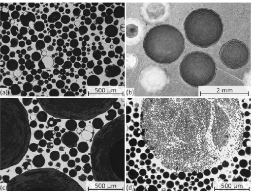
Metal matrix syntactic foams (MMSFs) are multiphase materials, consisting of a metallic matrix and a set of hollow inclusions (Fig. 1.).[1] Due to these constituents the MMSFs can be also sorted into a special group of particle reinforced composites and therefore they are often referred as composite metal foams (CMFs). Based on this MMSFs are considered as three phase (matrix – hollow sphere wall – void in the hollow sphere) or four phase (matrix – hollow sphere wall – void in the hollow sphere – unintended porosity in the matrix between the hollow spheres) materials. Sometimes the so-called interface layer, formed on the surface of the hollow spheres in contact with the matrix material is also considered as a further phase, especially in the cases when chemical reactions between the constituents are probable. By mixing the reinforcing hollow sphere grades, hybrid MMSF can be also produced.
Fig. 1. The structure of MMSFs (a) simple MMSF, (b) hybrid MMSF reinforced by two hollow sphere grades, (c) hybrid MMSFs reinforced by bimodal ceramic hollow spheres and (d) MMSFs reinforced by unidirectional Al2O3 fibers
The main two types of hybrid MMSFs are (i) the MMSFs that are filled by two or more different material hollow sphere sets and (ii) the bimodal (or multimodal) MMSFs[2][3] (Figs.
1b. and 1c., respectively).[3]–[6] Besides this, MMSFs can be integrated with the concept of unidirectionally (or multi directionally) reinforced composites (Fig. 1d.). By the mixing of the above mentioned possibilities materials scientists can engineer metallic foams with unique and outstanding – tailored – properties. The predecessors of MMSFs were produced with polymer matrix and they were developed for deep sea applications, such as the insulation of oil pipes or submarines.[7] Theoretically, MMSFs can be produced from any kind of metals, however their matrix is usually a grade of lightweight alloy (most commonly from the family
of Al[8]–[18] or Mg[19]–[22] alloys). Besides these, Fe[23]–[28], Zn[29]–[31] and Ti[32]–[34] based variations have been produced and reported in the literature. Even attempts to produce MMSFs with metallic glass matrix have been done.[35] The filler material (or reinforcement in the composite technologist point of view) is usually built up from oxide ceramics or from iron based metals (steels).[3][6][13][36][37] In the group of ceramics most commonly ‘fly-ash’[22][38]–[49]
(in some cases surface treated fly-ash[29]), alumina[50]–[54] or silicon carbide[4][52]–[54] are applied. Fly-ash is a by-product of coal power plants, they are quite cheap and available in large quantities, however their chemical composition can significantly vary and the scatter in their diameter is relatively high. These drawbacks can have serious negative effects on the mechanical properties of the produced MMSFs. A drawback of MMSFs reinforced by more controlled chemical composition materials connects to the wall material of the filler, because these hollow spheres are quite expensive (especially the pure Al2O3 and SiC hollow spheres), but this disadvantage can be easily equalized by the extremely high specific mechanical properties of MMSFs compared to ‘conventional’ metallic foams as it will be detailed later.[55-
57] To decrease this drawback, MMSFs with cheaper filler material, namely expanded perlite[58]–[68] and pumice[69] were developed. These MMSFs can preserve the advantageous mechanical properties, moreover they provide the possibility to produce low cost material.
It is also worth to mention, the mechanical properties of MMSFs can depend not only on the properties of the constituents, on the porosity (intended and / or unintended), but on the basic structure (the spatial distribution and arrangement of the hollow inclusions) of the foams themselves. For example, MMSFs can be produced by the infiltration of a hollow sphere preform, or by mixing the hollow spheres into the metallic matrix. In the first case the spheres will be in physical contact, while in the second case the spheres may be sperated from each other by the matrix materials. It is obvious, the mechanical properties will not be the same, for example one can mention the crack propagation in the foams describe above. In the first case a crack can propagate from spheres to spheres and in the case of ceramic hollow spheres, theie
brittleness will result in fast crack propagation. In the second case a crack initialized in a hollow sphere may be stopped in the ductile matrix, before it reaches the neighboring ceramic hollow sphere and therefore will exhibit a slower crack propagation and longer fatigue life.
As the member of the metallic foams’ family, the most common loading mode of MMSFs is compression, but they have been tested in all basic loading mode, including bending and tension.[54][68][70][71] However, nowadays only the compression test is standardized.[72] In this standard the generic main mechanical properties (stress and strain) are defined along with the characteristic strength values (compressive strength, plateau stress, quasi-elastic gradient, elastic gradient, compressive offset stress, compressive proof strength) and the characteristic strain values (for example the deformation at the plateau end). Suggestions for ideal sample geometries are also included in the standard. As the first applications of the MMSFs aimed to be collision and mechanical dampers, energy absorption and energy absorption efficiency are also defined. The standard is available from the end of 2011 (it was published on the 15th December 2011) and its predecessor (DIN50134:2008[73]) is available from October 2008.
Due to this, in the early papers, there are certain differences in the interpretation and determination of the most important mechanical properties. Therefore, in this paper the most important characteristic properties mapped by the active research groups in the field are listed and discussed. In this way, the main goal of this paper is to summarize the available, reasonable amount of results in order to ensure a stand-point for the designers.
2. Compressive strength
Compressive strength (σC) is normally defined as the first stress peak in the engineering stress – engineering strain curve that is calculated from the recorded force – displacement curve on the basis of original cross-section area and original height. Naturally, the use of the true system – correlated to the actual cross-section area and the actual height of the sample – would be better and more precise, however the actual load bearing cross-section is hard to
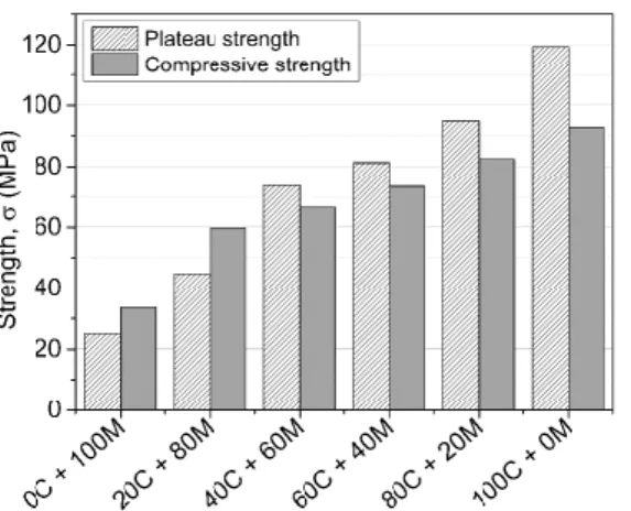
measure correctly (the actual load bearing cross-section area can be estimated by the volume fraction of the filler material, however due to the struts between the filler particles the material itself has a kind of special micropolar nature). Besides, MMSFs with lower hollow sphere content and / or with hollow spheres that are able to deform plastically may not have local maximum in their force – displacement curves and therefore the compressive strength is harder to determine. In this case compressive strength can be substituted by the so called compressive offset stress (σY) defined as the plastic compressive stress at a specified plastic deformation (usually at 0.2% unless it is specified otherwise). In Fig. 2. the compressive engineering stress – engineering strain curves of MMSFs with mixed hollow spheres are plotted.[5]
Fig. 2. The compressive and plateau strength values of MMSFs filled with different mixture of ceramic (C) and metallic (M) hollow spheres
In this case the reinforcement was provided by the mixing of ceramic (C) and metallic (M) hollow spheres. The hollow spheres had almost identical outer diameter and the legend of Fig.
2a. describes the distribution of the ceramic and metallic hollow spheres within the overall 64 vol% reinforcement (for example 20C+80M denotes a hybrid MMSF in which 20% ceramic
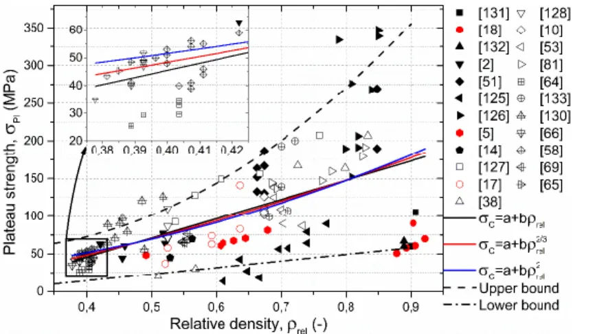
and 80% metallic hollow spheres can be found in the overall 64 vol% reinforcing phase). In Fig. 2b. the compressive and the 0.2% offset strength are visualized, respectively. It has to be mentioned the existence of distinguished peak in the force – displacement curve can be often related to the damage mechanism of the MMSFs, namely the stress peak often connects to the appearance of a shear plane in the specimen, closing 30-45°with the loading direction and hosting a cleavage like crack. That means concentrated damage and deformation in a smaller volume of the specimen. Contrary, smooth stress – strain curves often refers to the disperse, homogeneous and even plastic deformation of the sample. In this case the whole volume of the specimen is deformed and the energy absorption can be significantly higher. Fig. 3. shows the compressive strengths versus relative density chart of the MMSFs available in the professional literature.
Fig. 3. The compressive strength of the MMSFs as the function of relative density
Generally, the compressive strength is increasing with the increment of the relative density, as it is represented by the fitted lines. Basically, a linear fitting can be used to describe the trends (black continuous line in Fig. 3.), however for easier design the 2/3 (bending of beams, red
line in Fig. 3.) and 1/2 (bending of panels, blue line in Fig. 3.) power of the strength are also plotted. In the professional literature of metallic foams similar charts have been published.[74]
The fitted lines have a relatively low R2 value around 0.5, therefore it is worth to consider the boundary lines of the measured values. The upper boundary is plotted by a parabolic fit on the highest compressive strength at the given relative densities, respectively. Equation (1) represent the fitted upper bound.
σC= 507.07ρrel2 + 377.21ρrel− 175.73 (1)
While the lower boundary can be described by a simple line, represented by Equation (2).
σC= 20.48ρrel+ 12.91 (2)
In equations 1 and 2 the relative densities should be substituted in without dimension and the results will be in MPa.
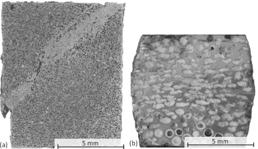
Besides the actual compressive strength of the investigated and listed materials another important viewpoint is in the deformation and in the damage mechanism of the MMSFs. As it was mentioned above in connection with the shape of their compressive engineering stress – engineering strain curves, MMSFs usually exhibit two different damage mechanisms to be short (Fig. 4.).
Fig. 4. Typical cleavage (a) and diffuse (b) damage of MMSFs
In most cases due to the relatively hard and brittle inclusions or filler materials, MMSFs’
deformation show cleavage in nature, that means the damage is concentrated in a certain and relatively thin layer closing 30-45° to the direction of compressive loading. The sample halves can slide on each other along this plane at a quite high stress level and can absorb more mechanical energy. MMSFs exhibiting this kind of damage behavior are plotted by black markers in Fig. 3. On the other hand, MMSFs can exhibit diffuse damage that occurs in the case of relatively soft filler material (for example low carbon content steel or stainless steel), or in the case of very thin walled ceramic hollow spheres. In this case, the deformation is widespread and later involves the whole volume of the sample. These kind of materials (highlighted by red color in Fig. 3.) typically have smaller strength values, however they can be found along almost the full relative density scale (between the relative density of 0.5 and 0.75, respectively). An important note has to mentioned here, namely the deformation and damage mechanism of MMSFs is not depending only on the constituents and structure of the material, therefore it not a materials property, only a state of the material, that can be modified
by state variables, like temperature or more complex stress states. Examples for the latter case can be found in the literature in the case of MMSFs in constrained deformation.[11][75][76] In general, the constrained, three axes loading results in diffuse failure mechanism even in the case of brittle MMSFs, due to the suppression of the relative movement (sliding) of the sample halves.[11][75]
Regarding the compressive strength of the MMSFs a number of models were developed to predict the first peak in the compressive engineering stress – engineering strain curves.
Amongst the first ones Kiser developed a model that takes into account the matrix strength besides the geometry parameters and the volume fraction of the inclusions. The model is represented in Equation (3).
σC= Cσym(1 − V (1 − 2t
D)3)
n
(3), where σym is the yield strength of the matrix, V is the hollow spheres’ volume fraction , t and D are the wall thickness and diameter of the hollow spheres, respectively. C and n are experimental constants that can be determined by fitting the equation to the measurements and are determined as 5 and 3, respectively in the cited paper.[11] A modified model published by Wu considered the strength of the hollow spheres wall and their contribution to the
compressive strength. The proposed model is presented by Equation (4).
σC= C (σym(1 − V)n+ σfwV (1 − (1 − 2Dt)3)
n
) (4),
where σfw is the fracture strength of the inclusion’s wall. The materials constants C and n were reported to be 0.3 and 1.5, respectively.[14] Later Mondal proposed a modification to the model to be more precise and suggest to take into account the porosity of the hollow spheres’
walls (see Equation (5)).
σC= C(σym(1 − V)n+ Cσfw((1 − Vi)(1 − Vw))n) (5), where Vi is the hollow space in the inclusion and Vw is the porosity within the sphere wall. In this model the material constants C and n were found to be 0.75 and 2.19, respectively.[34]
Mainly focusing on experimentals, Rohatgi et al. suggested a mathematical model that can predict many characteristic properties such as the peak stress, the plateau stress, the densification strain, and the composite density of ceramic hollow sphere filled MMSFs subjected to free (unconstrained) compression.[51][53] The results proved excellent agreement to the experimental data gathered from the literature.[52] The compressive strength can be calculated by Equation (6).
σC= (2𝐴𝑚σym+ 𝐴𝑆𝜂σfw) (𝐴𝐴𝑤
𝑠) (6),
where Am is the load bearing cross-section of the matrix material, As is the area in the investigated cross-section covered by the spheres, η is a factor that takes into account the porosity of the sphere walls and finally Aw is the area in the investigated cross-section covered by the wall of the spheres. The authors noted that, this expression is only valid above a certain ratio of Aw and As.[52]
In many cases MMSFs are built in environments where their deformation is significantly hindered in one or more directions. These cases indicated the investigations of MMSFs in constrained deformation circumstances.[11][75]–[77] The results showed that the MMSFs in constrained deformation have a very characteristic, but significantly different stress – strain curves. Most interestingly, absorbed mechanical energy was influenced by the circumstances of the compression: the absorbed energies were measured to be at least 2.5 times higher than in unconstrained compression. In constrained compression – as it was mentioned above – all the hollow inclusions in the samples were collapsed in the direction of the compressive loading, and the specimens exhibited large plastic deformation in their whole volume.[75][76]
Moreover, Kiser developed a Gurson based method to predict the compressive strength of MMSFs in radially constrained compression, with a only a relative wall thickness dependent effective strength.[11]
The opinion on the effect of higher strain rate in compressive tests is quite divided in the professional literature. The published papers have a common understanding in that the
elevated strain rate causes higher compressive strength except in the case of SiC reinforcement (see Table 1.).
Table 1. Literature data for the compressive strength of MMSFs
Matrix Filler Compressive strength (MPa) Q-S Dynamic Ref.
Cp-Al
SL75 65 vol% (<75 μm)
109 140@2300 s-1
Al7075-O 199 231@2300 s-1 [17]
Al7075-T6 229 248@2300 s-1
Al4032 Fly-ash 5 vol% (44-106 μm) 254
219@754 s-1 256@1293 s-1 [78]
280@1629 s-1 288@2136 s-1
A356 SiCHS 60 vol% (1 mm) 163
124@940 s-1
[9]
[55]
119@970 s-1 125@1160 s-1 123@1165 s-1 121@1220 s-1 119@1310 s-1 130@1425 s-1 125@1520 s-1
A380 Al2O3 40-50 vol% (0-0.5 mm) 165 160@1000 s-1 [53]
Al2O3 40-50 vol% (1-2 mm) 120 140@1000 s-1
Al6061 Cenospheres 45 vol% (200 μm) 45 48@2650 s-1 [79]
55@3350 s-1
Cp-Al
Cenospheres 70 vol% (90 μm) 75 108@1400 s-1
[80]
114@3000 s-1 119@5000 s-1 Cenospheres 65 vol% (150 μm) 45
65@2200 s-1 69@4400 s-1 69@5000 s-1
Al2014
Cenospheres 34 vol% (90 μm) 184
190@1 s-1
[16]
[81]
195@10 s-1 197@420 s-1 223@750 s-1 210@900 s-1 204@1400 s-1 Cenospheres 35 vol% (200 μm) 161
167@1 s-1 187@10 s-1 206@750 s-1 197@1400 s-1
A356
Globomet 316~65 vol% (2.2 mm) 82 88@1780 s-1
[82]
[83]
[84]
87@1465 s-1 Globomet 316 ~65 vol% (4 mm) 75 105@1431 s-1 Globomet 316~65 vol% (5.2 mm) 83 90@1922 s-1
85@767 s-1
3. Plateau strength
The role of plateau strength is to represent an average stress level between previously defined strain values. The higher the plateau strength is; the higher mechanical energy can be absorbed during the whole deformation process. According to its definition the plateau strength depends on the compressive strain rate on which the average stress has been
calculated. The plateau section of the MMSFs is usually uneven and wavy, however it is often modelled by a constant line. The plateau strength can be increasing thanks to the strain hardening and densifying of the matrix material. The plateau strength values, extracted from the relevant papers from the literature are plotted in Fig. 5. For better understanding the color coding of the figure is identical to the case of Fig. 3.
Fig. 5. The plateau strength of the MMSFs as the function of relative density
Regarding the relative density, the plateau strength values show a certain scatter, therefore their boundaries have been determined similarly, by fitting a parabola on the upper and a line on the lower plateau strength values. The upper and lower boundaries can be described by Equations (7) and (8), respectively.
σPl= 701.56ρrel2 − 346.12ρrel+ 98.92 (7)
σPl= 87.31ρrel− 20.64 (8) In the case of compression in confined geometry and constrained deformation it is hard to determine an expressed plateau strength, due to the ever increasing strength level.
Rohatgi et al. were able to develop a calculation method to predict the plateau strength of MMSFs, represented in Equation (9). The expression was derived assuming an ideal description of the yielding behavior of the syntactic foam that means the elastic deformation of the material is thought to be negligible and the overall plastic deformation is assumed to be approximately equal to the densification strain. Without further derivation:
σPl=σmin+σC
2 (9),
where σmin is the minimal stress value on the second part (after the first local strength peak) in the recorded compressive engineering stress versus engineering deformation curve, while σC
is the previously defined compressive strength.[52] This result is quite simple and only applicable for rough predictions, however, no more precise method has been published yet, according to the authors’ best knowledge.
4. Stiffness
About ‘stiffness’, most materials scientist refer to the Young’s modulus of the materials, however Young’s modulus can be only correctly interpreted for homogeneous, isotropic materials. Due to the complex geometric structures of foams, the first linear section in the stress – strain curve should be rather called stiffness or structural stiffness. According to the standard[72] it can be determined by two methods: (i) by fitting a strain line on the linear part of the curve (quasi-elastic gradient), or (ii) by performing an unloading from 70% to 20% of the plateau strength and connecting these points (elastic gradient). The first method is quite easy to perform; however, it is quite subjective to determine the set of measured points for the line fitting. The results may vary even 10% depending on the selected points. The second method is more objective; however, it is hard to estimate the given percentages of a plateau
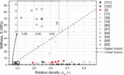
strength that is not yet determined. Authors have to note that, the measurement of the real elastic modulus (effective Young’s modulus) of an MMSF (or any foam) is not a trivial task, because extremely small loadings may cause plastic deformation due to the thin matrix struts between the hollow spheres.[85] The structural stiffness values of MMSFs are shown in Fig. 6.
with respect to their relative density.
Fig. 6. Structural stiffness values of MMSFs as the function of relative density
In Fig. 6. the stiffness values are grouped along two lines. Most of the MMSFs was measured to have a stiffness below 10 GPa, while specially designed, high strength, tailor made MMSFs exhibited higher stiffness values that increases approximately linearly with the relative density. In these foams the specially designed structure of the foams ensured the high strength and high stiffness.[86] Besides these results, high stiffness values was measured by Balch et al in ‘conventional’ MMSFs, by diffraction methods, that based on real, fully elastic
deformations only.[87] The upper limit can be described by Equation (10).
S = 166.49ρrel− 60.73 (10)
The lower limit is near to the horizontal zero line and can be expressed by Equation (11).
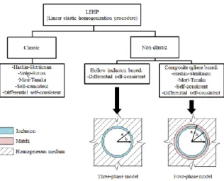
S = 0.23ρrel+ 0.70 (11) Based on the theories of elasticity the effective Young’s modulus of the MMSFs can be estimated. Bardella and Marur made many efforts in this field, during this process many homogenization procedures were applied. Fig. 7. helps to sort and summarize these methods.
Fig. 7. The system of the homogenization procedures.
Bardella and Genna focused their papers on the calculation of the elastic constants of (not only metallic, but) syntactic foams.[88]–[91] These works are dealing with three phase unit cell models taking into account the matrix, the hollow spheres’ wall and the porosity of syntactic foams. In a more complex approach MMSF filled sandwich structures were also studied.[71]
Marur has been worked with a very similar model.[92] A three phase model, consisting of matrix, hollow sphere and porosity was used to approximate the effective elastic properties.
The obtained values were compared to results from other theories and experimentals taken from the literature. Subsequently, the models were extended by the effect of the interfaces existing between the hollow spheres and the matrix. These interfaces are usually weak, but their effect on the elastic properties cannot be totally neglected.[93] Later, the previous results
and formalisms were checked by numerical calculations and the comparison with the applied model showed good agreement..[94] One step further, Porfiri and Gupta concentrated on the building of a general model to approximate the elastic properties for syntactic foams (and not only MMSFs) as function of particle volume fraction, size and wall thickness. The model can be successfully used in wide ranges of wall thicknesses and volume fractions to predict the effective elastic constants of MMSFs containing microballoons.[88] The previous examples showed that, the calculated results are often compared to numerical data. To obtain numerical results a correct model is required, that can be done by the structural modelling of existing foams. A common method to perform a satisfying reconstruction is to scan the samples by X- ray tomography methods[95]–[98], moreover an algorithm to identify and the geometric features in the scanned images are highly needed and therefore developed (for example by Zsoldos et al).[99]
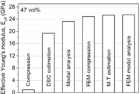
Recently, Szlancsik et al. have made efforts to measure the effective Young’s modulus of MMSFs by modal analysis.[85] In their work conventional compressive tests, modal analysis and their finite element models were applied to determine the effective Young’s modulus. For better results and correct measurements, the conventional compressive tests were
complemented by precise (extensometer) height measurements and small loading (<5 MPa).
Besides the measurements, the differential self-consistent and the Mori-Tanaka models were also applied to estimate the effective Young’s moduli. As an example, the results for Al99.5 matrix and 47 vol% Globocer (Al2O3 in 38 wt%, SiO2 in 43 wt% and and 3Al2O3·2SiO2
(mullite) in 19 wt%, provided by Hollomet GmbH.), average diameter and wall thickness of 1425 µm and 60 µm, respectively) hollow spheres are plotted in Fig. 8.
Fig. 8. Comparison of the effective Young’s moduli, determined from the compressive tests, analytical calculations, modal analysis and their FEM for 47 vol% hollow sphere content.
Szlancsik et al. concluded that, the modal analysis is suitable method to measure the effective Young’s modulus of MMSFs and due to this it also provides an easy and simple methodology to determine elastic properties. Furthermore, the extensometer complemented compression test is an adequate method to determine the structural stiffness of MMSFs, but it is not able to provide reliable data about the effective Young’s moduli. Regarding the estimation methods, the Mori-Tanaka solution provides the best prediction for the effective Young’s modulus.[85]
5. Energy absorption
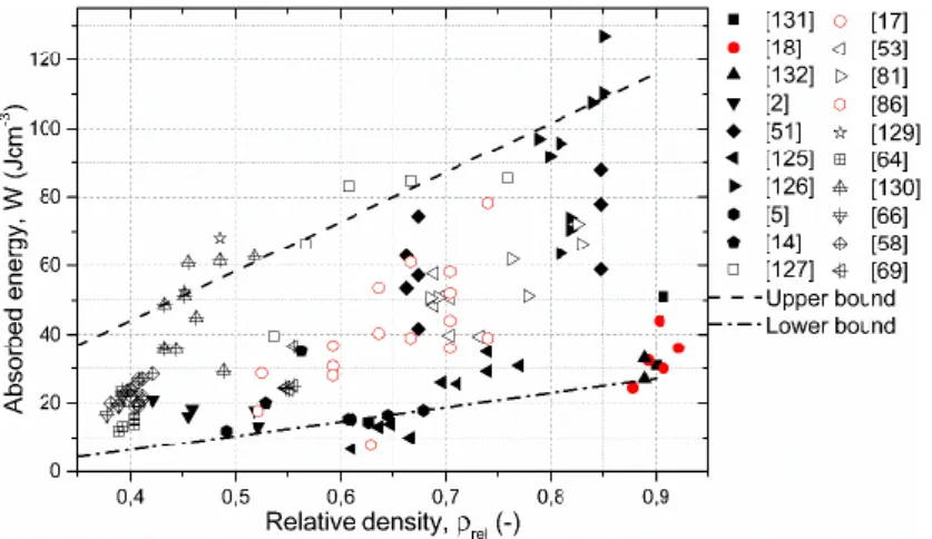
Energy absorption capability is quite important in the case of foams, because their main applications are often connected to the damping of collisions or other mechanical impacts. In the standard, the energy absorption is characterized by the area under the stress – deformation curve. Hereby we have to note that this characterization would be more precise if the true system is used instead of the engineering system. The area under the curve can be calculated by numerical integration, running from zero deformation up to a given upper limit that is preferably 50% strain or the end of the plateau region. In certain cases, other upper limits are
imaginable; therefore, it is important to clearly highlight the end strain in the reports. The absorbed energy values that are published in the literature are shown in Fig. 9.
Fig. 9. Absorbed energy values of the MMSFs as the function of relative density
The absolute value of energy absorption can help a designer to construct a part, but it cannot give an insight into the real performance of the material itself. To overwhelm this defect, the energy absorption efficiency was introduced. This factor compares the energy absorption of the material to the energy absorption of an ideal foam that is calculated by the product of the maximum stress and the upper limit of the strain, that is used to calculate the energy absorption. Due to this definition the energy absorption efficiency always remains below unity. The higher the efficiency is the higher volume of the foam is involved in the energy absorption process.
The energy absorption is also influenced by the strain rate, similarly to the compressive strength. The data available reliably from the published literature is listed in Table 2.
Table 2. Gathered data from the literature for the energy absorption of MMSFs
Matrix Filler Energy absorbtion (JcmQ-S Dynamic -3) Ref.
Cp-Al SL75 65 vol% (<75 μm) 55@60% - [17]
Al7075-T6 36@25% -
A380 Al2O3 40-50 vol% (0-0.5 mm) 48@40% - [53]
Al2O3 40-50 vol% (1-2 mm) 39@47% -
Al6061 Cenospheres 45 vol% (200 μm) 18@47% 28@43%@2650 s-1 [79]
33@43%@3350 s-1 Cp-Al Cenospheres 70 vol% (90 μm) 27@40% 40@40%@5000 s-1 [80]
Cenospheres 65 vol% (150 μm) 17@40% 29@40%@5000 s-1
Al2014
Cenospheres 34 vol% (90 μm) 56@30%
56@30%@1 s-1
[16]
[81]
50@30%@10 s-1 70@30%@750 s-1 64@30%@900 s-1 60@30%@1400 s-1 Cenospheres 35 vol% (200 μm) 51@30%
51@30%@1 s-1 50@30%@10 s-1 63@30%@750 s-1 58@30%@1400 s-1
A356
Globomet 316~65 vol% (2.2 mm) 41@50% 43@50%@1780 s-1
[82]
[83]
[84]
43@50%@1465 s-1 Globomet 316 ~65 vol% (4 mm) 37@50% 38@50%@1431 s-1 Globomet 316~65 vol% (5.2 mm) 5@10% 10@10%@1922 s-1
7@10%@767 s-1
6. Fatigue properties
The behavior of MMSFs under cyclic load is extremely interesting, while numerous applications results in repeated loading with more or less constant or changing amplitude.
However, only a limited number of publications have been published in this subject and most contributions have been focused on the ‘conventional’ structure (not MMSF) open or closed cell foams without any reinforcement. In the following paragraphs these publications are introduced.
Ashby et al. provided a summary on the fatigue properties of different aluminum alloy based metallic foams, considering the tension, compression or shearing loads. Prescriptions on the sample geometries and on the circumstances of the tests were suggested.[74] Replicated aluminum based foams with ~0.4 mm average pore size were tested in cyclic tension by Soubielle et al with stress asymmetry factor of 0.1. The foams displayed small cyclic deformation, strongly influenced by the relative density of the investigated replicated
foams.[100] Closed cell foams produced by powder metallurgy were tested by Amsterdam et al.
in cyclic and monotonic tension.. The cyclic tensile load resulted in a low speed deformation (ratchetting) of the samples, followed by an accelerated deformation finally lead in the fracture of the specimens.[101] Harte et al. investigated the fatigue failure of series produced open and closed cell aluminum alloy foams. The investigated loading modes included cyclic tension and compression modes. During the tests, the open cell foams with relatively uniform microstructure proved homogeneous deformation. Contrarily, the closed cell foam with more irregular microstructure exhibited a single and expressed crush zone that deformed and widened with each additional fatigue cycle.[102] McCullough and Fleck investigated AlMgSi alloy based foams under cyclic tension and compression conditions. The foams were closed cell and they were in the 0.1-0.4 relative density range. They observed an increasing fatigue strength with respect to an increasing relative density of the foams. Regarding the failure mechanism, again, ratchetting found to be the most dominant.[103] Banhart and Brinkers studied powder metallurgy produced Al-Si alloy (Al + 7 wt% Si) closed cell foams with different relative densities. During the production 0.5 wt% TiH2 was used as blowing agent (),. The samples were cylinders in shape and they were loaded in pulsing compression mode.
The authors emphasized that the compressive strength and moreover the choice of the failure criterion are not trivial in the case of metallic foams, as the fatigue limit of the investigated materials strongly depends on the chosen deformation limit as failure limit.[104] Technical purity Al foams again with blown structure were investigated in repeated compression by Sugimura et al. The most significant novelty in this contribution was the strain mapping of the samples’ surface by the use of image analysis. This method allowed to record strain maps and made possible to follow the appearance and widening of the deformation bands. The authors found that, closed cell Al foams had a quite well-defined fatigue limit (knee-point) in cyclic compression, connected to the cell walls membranes plastic buckling.[105] Zhou and Soboyejo tested Mg and Si alloyed open cell aluminum foams in constant amplitude repeated
compressive loading conditions. The tests finished in extensive micro and macro crack nucleation on the struts surfaces. The appeared cracks in the involved struts started to propagate until final fracture occurred in each individual strut. Due to the failure of each element of the open cell structure, the load (cannot be taken by the failed strut) was transferred to the near struts that cannot withstand to the increased loading. This process accelerated the fatigue damage and the extensive formation of wide deformation belt(s). The sudden appearance of such a deformed band caused sharp strain jumps in the resulted strain – cycle curves..[106][107] Lehmhus et al. studied Al6061 alloy foams produced by powder metallurgy in as produced and in precipitation hardened (T6) condition in cyclic compressive loading. The effect of T6 treatment (mainly the strength increment under quasi static loading) was only partially observed under of cyclic loads.[108] The work of Lin et al. highlighted the application of biocompatible, TiNb foams in medical applications (for example in the case of bone replacements, implants).[106][107] The cracks that are responsible for the fatigue failure of the porous TiNb system were started on the struts surfaces in the vicinity of the biggest pores, where the loading was concentrated only to a limited number of struts.[109] Therefore the pore size control in these applications has outmost importance. Hakamada’s research group focused their work on spacer method (NaCl space holders) produced closed cell Al foams subjected to cyclic loading. The foams were produced in a spark plasma sintering equipment.
Despite the similar structure to the previously mentioned foams, in this case the cyclic compression resulted in the gradually increasing strain again; however no distinct and expressed strain jumps (and corresponding deformation bands) were observed in the samples.[110] Zettl et al. studied closed cell foams, produced by powder metallurgy from AlSi and / or AlMgSi alloys., by fatigue testing in the ultrasound frequency domain under fully reversed tension-compression loading. The loading mode was a fully reversed alternating load with stress asymmetry factor of R=-1. During the damage accumulation the first serious cracks appeared at critical sites around precracks or original defects from the production
method (holes, pores etc.). The appearance of failure sites was probabilistic and
homogeneous, no critical deformation zones were found. As an important result, the effect of frequency magnitude proved to be insignificant within three decades.[111][112] Kim and Kim extensively studied the effect of aspect ratio (height to diameter ratio) on the mechanical properties of closed cell AlSiCa foams. The cyclic compressive tests proved that the foams with higher aspect ratio had higher fatigue limit and the damage accumulation process (that was ratchetting) started later.[113] Kolluri et al. subjected closed-cell Al foams to constant amplitude pulsing compressive load in laterally constrained and free condition. The results indicated that only the rapid strain accumulation stages behavior were sensitive to the constraint while the early stages of strain accumulation can be considered independent on the radial constraint.[77] Moving forward to the direction of more complex structures, Harte et al.
investigated Al foam core sandwich beams in cyclic four-point-bending . This study highlighted that a continuous reduction in the bending strength of the sandwich beams can be experienced in repeated loading compared to quasi-static load.[114] As an application, Schultz et al. managed to investigate potential helicopter components that contain foams.[115]
As it is detailed above, most of the investigations were performed at different frequency levels (however, researchers found that the effect of load frequency is negligible), while they are generally common in the applied stress asymmetry factor, taken to be R=0.1 usually..[111][112]
In the same time, the authors have to note that the MMSFs (or CMFs, by definition) have been not really mentioned and the above studies focus on ‘conventional’ foams. The only work in the knowledge of the authors was published by Vendra et al from prof. Rabiei’s research group. The researchers investigated CMFs contain steel hollow spheres in Al matrix and steel hollow spheres in steel matrix, produced by gravity casting and by powder metallurgy, respectively. Under cyclic compressive load, the CMFs showed high cyclic mechanical stability, especially in the beginning and the deformation could be divided into three regions (Fig. 10.). In stage I the deformation was almost linear with respect to the
number of cycles. In stage II minimal deformation accumulated during a quite large amount of cycles and finally in stage III rapid deformation accumulation occurred and the sample was completely failed within very limited number of cycles.
Fig. 10. Idealized compressive deformation – number of cycles and deformation rate – number of cycles curves for MMSFs
A significant advantage of MMSFs compared to the ‘conventional’ foams is the uniform distribution of failure in the whole volume of the sample. No distinguished deformation zones were found.[116] This behavior was confirmed by Katona et al, in the case of MMSFs
reinforced by Globocer or SL300 (provided by Envirospheres Pty. Ltd., with almost identical chemical composition as the Globocer hollow spheres, but one magnitude smaller average diameter and wall thickness) hollow spheres and with Al99.5 or AlSi12 matrix. By choosing a given deformation level and a required survival probability, the results can be evaluated by the classical methods of Weibull distribution function and fatigue design. The results are plotted in Fig. 11.
Fig. 11. Wöhler-like load ratio versus number of cycles curves for Al99.5 and AlSi12 matrix MMSFs reinforced by Globocer and SL300 hollow spheres
The authors concluded that, the commercial purity (soft) Al99.5 alloy matrix was able to provide higher load levels and therefore can accommodate more repeated load cycles than the more brittle AlSi12 matrix. Moreover, the larger Globocer grade ceramic hollow spheres showed better performance, because the smaller, SL grade spheres proved to be more vulnerable due to their thin wall and more densely packed structure. In that way, the cracks had to propagate shorter distances in the ductile matrix to the neighboring brittle ceramic sphere. In the case of these investigated MMSFs, one common failure mode was isolated: the samples were broken along a shear band, similar to the case of quasi-static loading.
7. Toughness, notch sensitivity
Although, to the actual knowledge of the authors, no information is available for MMSFs, a few papers have been published on the toughness, fracture behavior and crack propagation of conventional metallic foams.
McCullough et al. studied the fracture behavior of closed cell AlMg1Si0.6 and AlMg1Si10 foams. The effect of materials chemical composition and relative density on the toughness
was measured, and the precision of an existing micromechanical model was assessed.[117]
Olurin et al. described the compressive, tensile and fracture properties of metallic foams in terms of their microstructures.[118] They showed that, linear elastic fracture mechanics can be used to characterize fatigue crack propagation.[119] Motz et al. performed standard fracture mechanics tests on closed cell aluminum foams. The deformation measurements showed that a quite large fracture zone (6-8 cells) was developed.[120] The fatigue crack propagation tests proved a relatively high Paris-exponent in the range of 6…25.[121] Combaz and Mortensen conducted elastoplastic toughness testing (J-procedure) on pure aluminum replicated foams.
Resulting data showed pronounced R-curve behavior, the computed J values increased steadily beyond the crack blunting line before reaching a plateau. Fractography revealed crack propagation via the rupture of struts normal to the crack plane, while intact and fractured struts coexisted over a significant portion of the crack plane.[122] Kashef et al. characterized the fracture behavior of titanium foams and the R-curves of crack propagation from pre- cracks were measured.[123] Later, mode I fatigue crack propagation in 60% porous titanium foams both with and without solid coated surface was investigated. The crack extension rates could be well described by the Paris-power law approach.[124]
Besides the above mentioned results, the authors performed preliminary measurements on notched and standardized MMSF samples with 25 mm wide three-point bending (TPB) geometry. The MMSFs were produced by pressure infiltration. The matrix materials were Al99.5 or AlSi12 aluminum alloys, while the reinforcement was ensured by Globocer grade hollow spheres. A typical load – notch opening curve and the corresponding photographs about the surface of the sample as well as the final fracture surface are shown in Fig. 12.
Fig. 12. Typical load – notch opening diagram (a), crack propagation (b-e) and crack surface (f)
Starting from zero load, the specimen is unharmed and ready for the test (Fig. 12b.), as the increasing load reached its maximum a crack initialized in the notch tip (Fig. 12c.), the crack path run along the interfaces between the hollow spheres and the matrix material (arrows in Figs. 12c. and 12d.). In the case of AlSi12 matrix, due to its relative brittleness (compared to Al99.5) normally an uncertainty appeared in the recorded load diagram (small amplitude
waves just after the peak). As the crack propagated, the load decreased gradually (Fig. 12a.).
In a point in the load – notch opening diagram a sudden drop appeared and the crack branched into two subcracks as it can be observed in Fig. 12e., shown by the arrows. Finally, the sample broke into two parts. Both crack surfaces of the sample were investigated by optical microscopy. One half of the broken surface is shown in Fig. 12f., in which the contours of the original, machined notch are highlighted by the white vertical lines. Left to the lines, the broken surface can be observed. Regarding the hollow spheres along the crack path, two phenomena are important: (i) the crack can go through the hollow spheres or (ii) the crack runs in the interface between the hollow sphere and the matrix, bypassing the hollow sphere.
In general, ~20 percent of the hollow spheres were broken, in the other cases the crack had to go around the hollow sphere, increasing the energy for fracture (the created new surface is significantly larger). Regarding the actual toughness of the material, these preliminary tests highlighted the need of further investigations and the J-dominant behavior of the MMSFs.
8. Concluding remarks
Based on the above detailed properties, one can conclude that, the special behavior of the MMSFs and the possibility to tailor their mechanical properties make the MMSFs an outstanding choice for special applications in which low density and high specific strength or stiffness or energy absorbing capability are required.
There is a limited number of research groups spread in the World (including, but not limited to the United States, India, China, the Middle-East and Europe) that are dedicated to the research of metallic foams, including MMSFs. Their efforts invested into the determination of the mechanical properties of MMSFs provide limit values for the structural design of MMSF parts, including special cases of constrained deformation, high strain rates, repeated loading and notched parts with stress concentrators. The published papers, dealing with these problems are extremely useful to have a better understanding on the behavior of MMSFs.
These efforts also reached the level of standardization through national (DIN) and international (ISO) standards.
References
[1] N. Gupta, P. K. Rohatgi, Metal Matrix Syntactic Foams Processing, Microstructure, Properties and Applications, DEStech Publications, Inc. Lancaster, PA, USA 2015. p.
370.
[2] X. F. Tao, L. P. Zhang, Y. Y. Zhao, Mater. Des. 2009, 30, 2732.
[3] K. Májlinger, G. Kalácska, I. N. Orbulov, L. Zsidai, B. Bozóki, R. Keresztes, Tribol.
Lett. 2016, 65, 16.
[4] A. Daoud, Mater. Sci. Eng., A. 2009, 525, 7.
[5] K. Májlinger, I. N. Orbulov, Mater. Sci. Eng., A. 2014, 606, 248.
[6] K. Májlinger, B. Bozóki, G. Kalácska, R. Keresztes, L. Zsidai, Tribol. Int. 2016, 99, 211.
[7] D. H. Kallas, C. K. Chatten, Ocean Eng. 1969, 1, 421.
[8] Q. Zhang, Y. Lin, H. Chi, J. Chang, G. Wu, Compos. Struct. 2017.
[9] D. D. Luong, O. M. Strbik, V. H. Hammond, N. Gupta, K. Cho, J. Alloys Compd.
2013, 550, 412.
[10] L. Licitra, D. D. Luong, O. M. Strbik, N. Gupta, Mater. Des. 2015, 66, 504.
[11] M. Kiser, M. Y. He, F. W. Zok, Acta Mater. 1999, 47, 2685.
[12] K. Myers, B. Katona, P. Cortes, I. N. Orbulov, Composites, Part A. 2015, 79, 82.
[13] A. Szlancsik, B. Katona, K. Májlinger, I. N. Orbulov, Materials. 2015, 8, 7926.
[14] G. H. Wu, Z. Y. Dou, D. L. Sun, L. T. Jiang, B. S. Ding, B. F. He, Scr. Mater. 2007, 56, 221.
[15] B. Zhang, Y. Lin, S. Li, D. Zhai, G. Wu, Composites, Part B. 2016, 98, 288.
[16] M. D. Goel, M. Peroni, G. Solomos, D. P. Mondal, V. A. Matsagar, A. K. Gupta, M.
Larcher, S. Marburg, Mater. Des. 2012, 42, 418.
[17] D. K. Balch, J. G. O’Dwyer, G. R. Davis, C. M. Cady, G. T. Gray, D. C. Dunand, Mater. Sci. Eng., A. 2005, 391, 408.
[18] L. J. Vendra, A. Rabiei, Mater. Sci. Eng., A. 2007, 465, 59.
[19] G. Anbuchezhiyan, B. Mohan, D. Sathianarayanan, T. Muthuramalingam, J. Alloys Compd. 2017, 719, 125.
[20] H. Anantharaman, V. C. Shunmugasamy, O. M. Strbik, N. Gupta, K. Cho, Int. J.
Impact Eng. 2015, 82, 14.
[21] X. Xia, J. Feng, J. Ding, K. Song, X. Chen, W. Zhao, B. Liao, B. Hur, Mater. Des.
2015, 74, 36.
[22] K. N. Braszczyńska-Malik, J. Kamieniak, Mater. Charact. 2017, 128, 209.
[23] D. D. Luong, V. C. Shunmugasamy, N. Gupta, J. Weise, J. Baumeister, Mater. Des.
2015, 66, 516.
[24] L. Peroni, M. Scapin, C. Fichera, D. Lehmhus, J. Weise, J. Baumeister, M. Avalle, Composites, Part B, 2014, 66, 430.
[25] D. Lehmhus, J. Weise, J. Baumeister, L. Peroni, M. Scapin, C. Fichera, M. Avalle, M.
Busse, Procedia Mater. Sci. 2014, 4, 383.
[26] L. Peroni, M. Scapin, M. Avalle, J. Weise, D. Lehmhus, Mater. Sci. Eng., A. 2012, 552, 364.
[27] G. Castro, S. R. Nutt, Mater. Sci. Eng., A. 2012, 553, 89.
[28] G. Castro, S. R. Nutt, Mater. Sci. Eng., A. 2012, 535, 274.
[29] A. Daoud, Mater. Sci. Eng., A. 2008, 488, 281.
[30] A. Sánchez-Martínez, A. Cruz, M. González-Nava, M. A. Suárez, Mater. Des. 2016, 108, 494.
[31] J. A. Aragon-Lezama, A. Garcia-Borquez, G. Torres-Villaseñor, Mater. Sci. Eng., A.
2015, 638, 165.
[32] N. Jha, D. P. Mondal, M. D. Goel, J. D. Majumdar, S. Das, O. P. Modi, Trans.
Nonferrous Met. Soc. China 2014, 24, 89.
[33] X. Xue, L. Wang, M. Wang, W. Lü, D. Zhang, Trans. Nonferrous Met. Soc. China 2012, 22, 188.
[34] D. P. Mondal, J. D. Majumder, N. Jha, A. Badkul, S. Das, A. Patel, G. Gupta, Mater.
Des. 2012, 34, 82.
[35] H. Lin, H. Y. Wang, C. Lu, L. H. Dai, Scr. Mater. 2016, 119, 47.
[36] K. Májlinger, Int. J. Mater. Res. 2015, 106, 1165.
[37] A. Szlancsik, B. Katona, K. Bobor, K. Májlinger, I. N. Orbulov, Mater. Des. 2015, 83, 230.
[38] P. K. Rohatgi, J. K. Kim, N. Gupta, S. Alaraj, A. Daoud, Composites, Part A. 2006, 37, 430.
[39] P. K. Rohatgi, R. Q. Guo, Tribol. Lett. 1997, 3, 339.
[40] P. K. Rohatgi, A. Daoud, B. F. Schultz, T. Puri, Composites, Part A. 2009, 40, 883.
[41] Q. Zhang, P. D. Lee, R. Singh, G. Wu, T. C. Lindley, Acta Mater. 2009, 57, 3003.
[42] R. Q. Guo, P. K. Rohatgi, Metall. Mater. Trans. B. 1998, 29, 519.
[43] P. K. Rohatgi, R. Q. Guo, H. Iksan, E. J. Borchelt, R. Asthana, Mater. Sci. Eng., A.
1998, 244, 22.
[44] T. P. D. Rajan, R. M. Pillai, B. C. Pai, K. G. Satyanarayana, P. K. Rohatgi, Compos.
Sci. Technol. 2007, 67, 3369.
[45] N. Sobczak, J. Sobczak, J. Morgiel, L. Stobierski, Mater. Chem. Phys. 2003, 81, 296.
[46] Z. Huang, S. Yu, M. Li, Trans. Nonferrous Met. Soc. China 2010, 20, 458.
[47] D. P. Mondal, M. D. Goel, S. Das, Mater. Des. 2009, 30, 1268.
[48] D. D. Luong, N. Gupta, P. K. Rohatgi, JOM. 2011, 63, 48.
[49] D. P. Mondal, M. D. Goel, S. Das, Mater. Sci. Eng., A. 2009, 507, 102.
[50] M. Y. Omar, C. Xiang, N. Gupta, O. M. Strbik, K. Cho, Data Br. 2015, 5, 522.
[51] J. A. Santa Maria, B. F. Schultz, J. B. Ferguson, P. K. Rohatgi, Mater. Sci. Eng., A.
2013, 582, 415.
[52] J. B. Ferguson, J. A. Santa Maria, B. F. Schultz, P. K. Rohatgi, Mater. Sci. Eng., A.
2013, 582, 423.
[53] J. A. Santa Maria, B. F. Schultz, J. B. Ferguson, N. Gupta, P. K. Rohatgi, J. Mater. Sci.
2014, 49, 1267.
[54] M. Y. Omar, C. Xiang, N. Gupta, O. M. Strbik, K. Cho, Data Br. 2015, 5, 564.
[55] J. Cox, D. D. Luong, V. C. Shunmugasamy, N. Gupta, O. M. Strbik, K. Cho, Metals.
2014, 4, 530.
[56] D. P. Mondal, S. Das, N. Jha, Mater. Des. 2009, 30, 2563.
[57] N. Jha, A. Badkul, D. P. Mondal, S. Das, M. Singh, Tribol. Int. 2011, 44, 220.
[58] M. Taherishargh, M. A. Sulong, I. V. Belova, G. E. Murch, T. Fiedler, Mater. Des.
2015, 66, 294.
[59] M. Borovinšek, M. Taherishargh, M. Vesenjak, Z. Ren, T. Fiedler, Mater. Charact.
2016, 119, 209.
[60] M. Taherishargh, B. Katona, T. Fiedler, I. N. Orbulov, J. Compos. Mater. 2017, 51, 773.
[61] S. Broxtermann, M. Taherishargh, I. V. Belova, G. E. Murch, T. Fiedler, J. Alloys Compd. 2017, 691, 690.
[62] T. Fiedler, M. Taherishargh, L. Krstulović-Opara, M. Vesenjak, Mater. Sci. Eng., A.
2015, 626, 296.
[63] M. A. Sulong, M. Taherishargh, I. V. Belova, G. E. Murch, T. Fiedler, Comput. Mater.
Sci. 2015, 109, 258.
[64] M. Taherishargh, I. V. Belova, G. E. Murch, T. Fiedler, Mater. Sci. Eng., A. 2014, 604, 127.
[65] M. Taherishargh, I. V. Belova, G. E. Murch, T. Fiedler, J. Alloys Compd. 2017, 693,
55.
[66] M. Taherishargh, I. V. Belova, G. E. Murch, T. Fiedler, Mater. Des. 2014, 63, 375.
[67] T. Fiedler, I. V. Belova, G. E. Murch, Int. J. Heat Mass Transfer. 2015, 90, 1009.
[68] M. Taherishargh, M. Vesenjak, I. V. Belova, L. Krstulović-Opara, G. E. Murch, T.
Fiedler, Mater. Des. 2016, 99, 356.
[69] M. Taherishargh, I. V. Belova, G. E. Murch, T. Fiedler, Mater. Sci. Eng., A. 2015, 635, 102.
[70] M. Y. Omar, C. Xiang, N. Gupta, O. M. Strbik, K. Cho, Mater. Des. 2015, 86, 536.
[71] L. Bardella, F. Genna, Int. J. Solids Struct. 2001, 38, 307.
[72] Mechanical testing of metals – ductility testing – compression test for porous and cellular materials, ISO 13314 standard. 2011.
[73] Testing of metallic materials – Compression test of metallic cellular materials, DIN 50134 standard. 2008.
[74] M. F. Ashby, A. G. Evans, N. A. Fleck, L. J. Gibson, J. W. Hutchinson, H. N. G.
Wadley, Metal Foams: A Design Guide, Butterworth-Heinemann, Wildwood, United Kingdom 2000. p. 251.
[75] I. N. Orbulov, K. Májlinger, JOM. 2014, 66, 882.
[76] I. Duarte, M. Vesenjak, L. Krstulović-Opara, Compos. Struct. 2016, 154, 231.
[77] M. Kolluri, M. Mukherjee, F. Garcia-Moreno, J. Banhart, U. Ramamurty, Acta Mater.
2008, 56, 1114.
[78] D. D. Luong, N. Gupta, A. Daoud, P. K. Rohatgi, JOM. 2011, 63, 53.
[79] L. C. Zou, Q. Zhang, B. J. Pang, G. H. Wu, L. T. Jiang, H. Su, Mater. Des. 2013, 45, 555.
[80] Z. Y. Dou, L. T. Jiang, G. H. Wu, Q. Zhang, Z. Y. Xiu, G. Q. Chen, Scr. Mater. 2007, 57, 945.
[81] M. D. Goel, D. P. Mondal, M. S. Yadav, S. K. Gupta, Mater. Sci. Eng., A. 2014, 590, 406.
[82] A. Rabiei, M. Garcia-Avila, Mater. Sci. Eng., A. 2013, 564, 539.
[83] Y. Alvandi-Tabrizi, D. A. Whisler, H. Kim, A. Rabiei, Mater. Sci. Eng., A. 2015, 631, 248.
[84] Y. Alvandi-Tabrizi, A. Rabiei, Procedia Mater. Sci. 2014, 4, 377.
[85] A. Szlancsik, B. Katona, Z. Dombóvári, I. N. Orbulov, Mater. Sci. Technol. 2017, 18, 2283.
[86] M. Javad Nayyeri, S. M. H. Mirbagheri, S. Amirkhanlou, Mater. Lett. 2015, 154, 152.
[87] D. K. Balch, D. C. Dunand, Acta Mater. 2006, 54, 1501.
[88] L. Bardella, A. Sfreddo, C. Ventura, M. Porfiri, N. Gupta, Mech. Mater. 2012, 50, 53.
[89] L. Bardella, Int. J. Eng. Sci. 2003, 41, 741.
[90] G. Tagliavia, M. Porfiri, N. Gupta, Mech. Mater. 2011, 43, 952.
[91] A. Panteghini, L. Bardella, Mech. Mater. 2015, 82, 63.
[92] P. R. Marur, Mater. Lett. 2005, 59, 1954.
[93] P. R. Marur, Comput. Mater. Sci. 2009, 46, 327.
[94] P. R. Marur, Finite Elem. Anal. Des. 2010, 46, 1001.
[95] E. Maire, P. Colombo, J. Adrien, L. Babout, L. Biasetto, J. Eur. Ceram. Soc. 2007, 27, 1973.
[96] J. Adrien, E. Maire, N. Gimenez, V. Sauvant-Moynot, Acta Mater. 2007, 55, 1667.
[97] S. Youssef, E. Maire, R. Gaertner, Acta Mater. 2005, 53, 719.
[98] E. Maire, Compos. Sci. Technol. 2003, 63, 2431.
[99] I. Kozma, I. Zsoldos, G. Dorogi, S. Papp, Period. Polytech. Mech. Eng. 2014, 58, 87.
[100] S. Soubielle, L. Salvo, F. Diologent, A. Mortensen, Mater. Sci. Eng., A. 2011, 528, 2657.
[101] E. Amsterdam, J. T. M. De Hosson, P. R. Onck, Acta Mater. 2006, 54, 4465.
[102] A. M. Harte, N. A. Fleck, M. F. Ashby, Acta Mater. 1999, 47, 2511.
[103] K. Y. G. McCullough, N. A. Fleck, Fatigue Fract. Eng. Mater. Struct. 2000, 23, 199.
[104] J. Banhart, W. Brinkers, J. Mater. Sci. Lett. 1999, 18, 617.
[105] Y. Sugimura, A. Rabiei, A. G. Evans, A. M. Harte, N. A. Fleck, Mater. Sci. Eng., A.
1999, 269, 38.
[106] J. Zhou, W. O. Soboyejo, Mater. Sci. Eng., A. 2004, 369, 23.
[107] J. Zhou, Z. Gao, A. M. Cuitino, W. O. Soboyejo, J. Eng. Mater. Technol. 2005, 127, 40.
[108] D. Lehmhus, C. Marschner, J. Banhart, H. Bomas, J. Mater. Sci. 2002, 37, 3447.
[109] J. Lin, Y. Zhang, M. Ma, Trans. Nonferrous Met. Soc. China 2010, 20, 390.
[110] M. Hakamada, T. Kuromura, Y. Chino, Y. Yamada, Y. Chen, H. Kusuda, M. Mabuchi, Mater. Sci. Eng., A. 2007, 459, 286.
[111] B. Zettl, H. Mayer, S. E. Stanzl-Tschegg, H. P. Degischer, Mater. Sci. Eng., A. 2000, 292, 1.
[112] B. Zettl, H. Mayer, S. E. Stanzl-Tschegg, Int. J. Fatigue. 2001, 23, 565.
[113] A. Kim, I. Kim, Acta Mech. Solida Sin. 2008, 21, 354.
[114] A. M. Harte, N. A. Fleck, M. F. Ashby, Int. J. Fatigue. 2001, 23, 499.
[115] O. Schultz, A. des Ligneris, O. Haider, P. Starke, Adv. Eng. Mater. 2000, 2, 215.
[116] L. Vendra, B. Neville, A. Rabiei, Mater. Sci. Eng., A. 2009, 517, 146.
[117] K. Y. G. McCullough, N. A. Fleck, M. F. Ashby, Acta Mater. 1999, 47, 2331.
[118] O. B. Olurin, N. A. Fleck, M. F. Ashby, Mater. Sci. Eng., A. 2000, 291, 136.
[119] O. B. Olurin, K. Y. G. McCullough, N. A. Fleck, M. F. Ashby, Int. J. Fatigue 2001, 23, 375.
[120] C. Motz, R. Pippan, Acta Mater. 2002, 50, 2013.
[121] C. Motz, O. Friedl, R. Pippan, Int. J. Fatigue. 2005, 27, 1571.
[122] E. Combaz, A. Mortensen, Acta Mater. 2010, 58, 4590.
[123] S. Kashef, A. Asgari, T. B. Hilditch, W. Yan, V. K. Goel, P. D. Hodgson, Mater. Sci.
Eng., A. 2010, 527, 7689.
[124] S. Kashef, A. Asgari, T. B. Hilditch, W. Yan, V. K. Goel, P. D. Hodgson, Mater. Sci.
Eng., A. 2011, 528, 1602.
[125] C. A. Vogiatzis, A. Tsouknidas, D. T. Kountouras, S. Skolianos, Mater. Des. 2015, 85, 444.
[126] M. Altenaiji, Z. W. Guan, W. J. Cantwell, Y. Zhao, G. K. Schleyer, Mater. Des. 2014, 59, 296.
[127] X. F. Tao, Y. Y. Zhao, Scr. Mater. 2009, 61, 461.
[128] X. F. Tao, Y. Y. Zhao, Mater. Sci. Eng., A. 2012, 549, 228.
[129] Y. Lin, Q. Zhang, G. Wu, J. Alloys Compd. 2016, 655, 301.
[130] Y. Lin, Q. Zhang, F. Zhang, J. Chang, G. Wu, Mater. Sci. Eng., A. 2017, 696, 236.
[131] A. Rabiei, L. J. Vendra, Mater. Lett. 2009, 63, 533.
[132] A. Rabiei, A. T. O’Neill, Mater. Sci. Eng., A. 2005, 404, 159.
[133] P. Yu, M. Qian, Mater. Chem. Phys. 2012, 137, 435.
Fig. 1. The structure of MMSFs (a) simple MMSF, (b) hybrid MMSF reinforced by two hollow sphere grades, (c) hybrid MMSFs reinforced by bimodal ceramic hollow spheres and (d) MMSFs reinforced by unidirectional Al2O3 fibers
Fig. 2. The engineering stress – engineering strain curves of MMSFs with mixed hollow spheres (a) and the visualization of the compressive strength and the offset strength (b)
Fig. 3. The compressive strength of the MMSFs as the function of relative density
Fig. 4. Typical cleavage (a) and diffuse (b) damage of MMSFs
Fig. 5. The plateau strength of the MMSFs as the function of relative density
Fig. 6. The structural stiffness values of the MMSFs as the function of relative density
Fig. 7. The system of the homogenization procedures.
Fig. 8. Comparison of the Young’s moduli, determined from the compressive tests, modal analysis and their FEM.
Fig. 9. The absorbed energy values of the MMSFs as the function of relative density
Fig. 10. Idealized compressive deformation – number of cycles curve for MMSFs
Fig. 11. Wöhler-like load ratio versus number of cycles curves for Al99.5 and AlSi12 matrix MMSFs reinforced by Globocer and SL300 hollow spheres
Fig. 12. Typical load – notch opening diagram (a), crack propagation (b-e) and crack surface (f)
Table 1. Literature data for the compressive strength of MMSFs
Matrix Filler Compressive strength (MPa)
Ref.
Q-S Dynamic Cp-Al
SL75 65 vol% (<75 μm)
109 140@2300 s-1
Al7075-O 199 231@2300 s-1 [17]
Al7075-T6 229 248@2300 s-1
Al4032 Fly-ash 5 vol% (44-106 μm) 254
219@754 s-1 256@1293 s-1 [78]
280@1629 s-1 288@2136 s-1
A356 SiCHS 60 vol% (1 mm) 163
124@940 s-1
[9]
[55]
119@970 s-1 125@1160 s-1 123@1165 s-1 121@1220 s-1 119@1310 s-1 130@1425 s-1 125@1520 s-1
A380 Al2O3 40-50 vol% (0-0.5 mm) 165 160@1000 s-1 [53]
Al2O3 40-50 vol% (1-2 mm) 120 140@1000 s-1
Al6061 Cenospheres 45 vol% (200 μm) 45 48@2650 s-1 [79]
55@3350 s-1
Cp-Al
Cenospheres 70 vol% (90 μm) 75
108@1400 s-1
[80]
114@3000 s-1 119@5000 s-1 Cenospheres 65 vol% (150 μm) 45 65@2200 s-1
69@4400 s-1 69@5000 s-1
Al2014
Cenospheres 34 vol% (90 μm) 184
190@1 s-1
[16]
[81]
195@10 s-1 197@420 s-1 223@750 s-1 210@900 s-1 204@1400 s-1 Cenospheres 35 vol% (200 μm) 161
167@1 s-1 187@10 s-1 206@750 s-1 197@1400 s-1
A356
Globomet 316~65 vol% (2.2 mm) 82 88@1780 s-1
[82]
[83]
[84]
87@1465 s-1 Globomet 316 ~65 vol% (4 mm) 75 105@1431 s-1 Globomet 316~65 vol% (5.2 mm) 83 90@1922 s-1
85@767 s-1
Table 2. Literature data for the energy absorption capability of MMSFs
Matrix Filler Energy absorbtion (JcmQ-S Dynamic -3) Ref.
Cp-Al SL75 65 vol% (<75 μm) 55@60% - [17]
Al7075-T6 36@25% -
A380 Al2O3 40-50 vol% (0-0.5 mm) 48@40% - [53]
Al2O3 40-50 vol% (1-2 mm) 39@47% -
Al6061 Cenospheres 45 vol% (200 μm) 18@47% 28@43%@2650 s-1 [79]
33@43%@3350 s-1 Cp-Al Cenospheres 70 vol% (90 μm) 27@40% 40@40%@5000 s-1 [80]
Cenospheres 65 vol% (150 μm) 17@40% 29@40%@5000 s-1
Al2014
Cenospheres 34 vol% (90 μm) 56@30%
56@30%@1 s-1
[16]
[81]
50@30%@10 s-1 70@30%@750 s-1 64@30%@900 s-1 60@30%@1400 s-1 Cenospheres 35 vol% (200 μm) 51@30%
51@30%@1 s-1 50@30%@10 s-1 63@30%@750 s-1 58@30%@1400 s-1
A356
Globomet 316~65 vol% (2.2 mm) 41@50% 43@50%@1780 s-1
[82]
[83]
[84]
43@50%@1465 s-1 Globomet 316 ~65 vol% (4 mm) 37@50% 38@50%@1431 s-1 Globomet 316~65 vol% (5.2 mm) 5@10% 10@10%@1922 s-1
7@10%@767 s-1