Institute of Applied Mechanics Faculty of Mechanical Engineering and
Informatics
University of Miskolc
László Péter Kiss
Vibrations and Stability of Heterogeneous Curved Beams
PhD thesis
István Sályi Doctoral School
Main Topic Group: Fundamental Sciences in Mechanical Engineering Topic Group: Mechanics of Solid Bodies
Head of Doctoral School:
Miklós Tisza
Doctor of Science, Full Professor Head of the Main Topic Group:
István Páczelt
Member of the Hungarian Academy of Sciences, Professor Emeritus Head of the Topic Group:
Imre Kozák
Member of the Hungarian Academy of Sciences, Professor Emeritus Scientific Supervisor:
György Szeidl
Doctor of Science, Professor Emeritus
Miskolc 2015
Declaration
The author hereby declares that the work in this thesis contains no material previously published or written by another person and no part of the thesis has been submitted, either in the same or dierent form to any other university for a PhD degree.
The author conrms that the work presented in this thesis is his own and appropriate credit is given in the text when (and where) reference is made to the work of others.
Miskolc, 27 April 2015
László Péter Kiss
Recommendation of the supervisor to the PhD thesis
Vibrations and Stability of Heterogeneous Curved Beams
by László Péter Kiss
As is well known curved structural elements have been used successfully in various engi- neering applications for their favorable load carrying capabilities. One can mention, without striving for completeness, arch bridges or stieners in roof- and shell structures etc. With technology developing and production volumes increasing it is gradually getting cheaper to manufacture heterogeneous or inhomogeneous curved beams, such as composites, laminates, sandwich structures. The thesis by László Péter Kiss is aimed to solve some (altogether three) fundamental problems concerning the mechanical behavior of heterogeneous curved beams.
The rst objective is a generalization of some classical results valid for homogeneous materials. These investigations have yielded some elementary relationships that can be used to determine the stress state in the heterogeneous curved beam by hand made calculations.
The second objective is to develop a new nonlinear model for non-strictly shallow curved beams from the principle of virtual work. This model makes it possible to determine the critical load both for symmetric snap-through and antisymmetric bifurcation buckling if the heterogeneous curved beam is subjected to a central load at the crown point. Pinned-pinned, xed-xed and elastically restrained beams are considered. The third objective is to clarify what eect the central load has on the frequency spectrum of the heterogeneous curved beam. The solution is based on reducing the corresponding eigenvalue problems to those governed by Fredholm integral equation systems.
The thesis systematically deals with the three problems and does its best to nd ap- propriate solutions. The numerical results were determined by developing and successfully running three programs which were coded in Fortan 90. This work needed a great care but László Péter Kiss solved this issue successfully.
As a scientic supervisor I should emphasize that László Péter Kiss is a hard working and diligent young man who did his work paying careful attention to every detail. The results achieved have been published regularly (four papers have come out and one paper is accepted) by fullling the requirements of the István Sályi Doctoral School for publications in this way.
The thesis presents the research work an its results in a clear and well-arranged manner:
the numerous gures provide a further help for the reader to understand what eect the various parameters have on the results (critical loads and natural frequencies). In accordance with the three objectives the three statements in the summary can be regarded as a short synopsis of the most important results.
Bükkszentkereszt, 27 April 2015 György Szeidl, DSc
Professor Emeritus
Contents
Nomenclature. . . IV
1. Preliminaries & Aims . . . 1
1.1. Heterogeneous curved beams . . . 1
1.2. Stresses in curved beams . . . 2
1.3. Stability issues of curved beams . . . 3
1.4. Vibrations of curved beams . . . 5
2. Stresses in heterogeneous circular beams . . . 7
2.1. Kinematical hypothesis . . . 7
2.2. Formulae for the normal stress distribution. . . 9
2.2.1. Generalization of the Grashof formula . . . 9
2.2.2. The normal stress under pure bending. . . 10
2.3. Formula for the shear stress . . . 12
2.3.1. The shear correction factor. . . 14
2.4. Curvature change and strain energy . . . 15
2.5. Numerical examples. . . 16
2.5.1. Example 1.. . . 16
2.5.2. Example 2.. . . 19
2.5.3. Example 3.. . . 21
2.5.3.1. The shear correction factor . . . 23
2.6. Summary of the results achieved in Section 2. . . 24
3. In-plane elastic stability of heterogeneous shallow circular beams . . . 25
3.1. Fundamental assumptions. . . 25
3.1.1. General relations regarding the pre-buckling state . . . 25
3.1.2. General relations for the post-buckling state . . . 27
3.2. Governing equations . . . 28
3.2.1. Equilibrium conditions in the pre-buckling state . . . 28
3.2.2. Equilibrium equations in terms of the displacements . . . 29
3.2.3. The principle of virtual work after the loss of stability . . . 29
3.2.4. Post-buckling equilibrium equations in terms of the displacements . . . 30
3.3. Solutions for the pre-buckling state . . . 31
3.3.1. General solution . . . 31
3.3.2. Pinned-pinned beams . . . 31
3.3.3. Fixed-xed beams. . . 33
3.3.4. Rotationally-restrained beams . . . 34
3.4. Possible solutions for the post-buckling state . . . 35
3.4.1. General solution . . . 35
3.4.2. Pinned-pinned beams antisymmetric buckling . . . 37
3.4.3. Pinned-pinned beams symmetric buckling . . . 37
3.4.4. Fixed-xed beams antisymmetric buckling . . . 39
3.4.5. Fixed-xed beams solution for symmetric buckling. . . 40
I
3.4.6. Rotationally restrained beams antisymmetric buckling . . . 41
3.4.7. Rotationally restrained beams symmetric buckling . . . 42
3.5. Computational results . . . 43
3.5.1. Pinned-pinned beams . . . 44
3.5.1.1. Antisymmetric bifurcation buckling. . . 46
3.5.1.2. Symmetric snap-through buckling . . . 47
3.5.1.3. Load-crown point displacement and load-strain ratios . . . 49
3.5.2. Fixed-xed beams. . . 51
3.5.2.1. Antisymmetric bifurcation buckling. . . 53
3.5.2.2. Symmetric buckling . . . 54
3.5.2.3. Load-crown point displacement and load-strain ratio graphs . . . 55
3.5.3. Rotationally restrained beams . . . 57
3.5.3.1. Antisymmetric and symmetric buckling. . . 61
3.5.3.2. The primary equilibrium paths and the load-strain relationships . . . 63
3.6. The eect of heterogeneity on the buckling load . . . 64
3.6.1. Numerical example. . . 67
3.7. Summary of the results achieved in Section 3. . . 68
4. In-plane vibrations of loaded heterogeneous deep circular beams . . . 69
4.1. Introductory remarks . . . 69
4.1.1. Equations of the static equilibrium . . . 69
4.1.2. Equations of the vibrations. . . 71
4.2. Solutions to the homogeneous parts . . . 72
4.2.1. The static equilibrium. . . 72
4.2.1.1. If mεoξ <1. . . 73
4.2.1.2. If mεoξ >1. . . 73
4.2.2. The increments . . . 73
4.2.2.1. Solution when mεoξ <1.. . . 74
4.2.2.2. Solution when mεoξ >1. . . 74
4.3. The Green function matrix. . . 75
4.4. Numerical solution to the eigenvalue problems. . . 77
4.5. Construction of the Green function matrices . . . 78
4.5.1. The structure of the Green function matrix. . . 78
4.5.2. The Green function matrix when mεoξ <1.. . . 78
4.5.2.1. Constants for pinned-pinned supports . . . 80
4.5.2.2. Constants for xed-xed supports.. . . 81
4.5.3. The Green function matrix when mεoξ >1.. . . 82
4.5.3.1. Constants for pinned-pinned supports. . . 83
4.5.3.2. Constants for xed-xed supports.. . . 84
4.6. The load-strain relationships . . . 84
4.6.1. Pinned-pinned beams.. . . 85
4.6.2. Fixed-xed beams. . . 85
4.7. The critical strain. . . 85
4.7.1. Pinned-pinned beams.. . . 86
4.7.2. Fixed-xed beams. . . 86
4.8. Computational results . . . 87
4.8.1. Results for unloaded pinned-pinned beams. . . 89
4.8.2. Results for loaded pinned-pinned beams. . . 91
4.8.3. Results for unloaded xed-xed beams.. . . 92
4.8.4. Results for loaded xed-xed beams. . . 94
4.8.5. The eect of heterogeneity on the frequency spectrum . . . 96
4.8.5.1. Free vibrations . . . 98
4.8.5.2. Loaded vibrations . . . 99
4.8.5.3. Finite element computations. . . 103
4.9. Summary of the results achieved in Section 4. . . 104
5. Outline . . . 106
5.1. Preliminaries. . . 106
5.1.1. Some mechanical issues of circular beams. . . 107
5.2. Objectives . . . 108
5.3. Investigations performed . . . 109
5.4. Summary of the novel results . . . 111
5.5. Magyar nyelv¶ összefoglaló (Summary in Hungarian) . . . 112
5.6. Possible application of the results . . . 115
5.7. Future research . . . 115
5.8. Related publications by the author . . . 116
Appendix A. Detailed manipulations 118 A.1. The long formal transformations of Chapter 3 . . . 118
A.1.1. Formulae for the axial force. . . 118
A.1.2. Transformation of the principle of virtual work pre-buckling state . . . 118
A.1.3. Transformation of the principle of virtual work post-buckling state . . . 119
A.1.4. The pre-buckling equilibrium in terms of the displacements . . . 121
A.1.5. The post-buckling equilibrium in terms of the displacements . . . 122
A.1.6. Computation of the pre-buckling strain . . . 123
A.1.7. Manipulations on the displacement increment . . . 124
A.1.8. The averaged strain increment . . . 127
A.2. Some additional transformations for Chapter 4 . . . 129
A.2.1. The static equilibrium . . . 129
A.2.2. Equations of the vibrations . . . 130
A.2.3. The load-strain relationship. . . 130
A.2.3.1. The equation system for pinned-pinned beams in Subsection 4.6.1 . . . 132
A.2.3.2. The equation system for xed-xed beams in Subsection 4.6.2 . . . 133
List of Figures . . . 134
List of Tables . . . 136
Bibliography . . . 138
Nomenclature
Here the most important and most commonly used notations are gathered in alphabetical order. Although each notation is described in the text when rst used, this Nomenclature might come handy at times.
Latin symbols:
A , A0 cross-sectional area, segment area (see Figure 2.3), Ae, A0e E-weighted areas,
AeR E-weighted reduced area, Aj,Bj matrices in the representation
of the Green function matrix (j = 1,2,3,4), Ce E-weighted centroid of the cross-section, eξ,eη,eζ orthogonal unit vectors,
E(η, ζ) Young's modulus,
E Green-Lagrange strain tensor,
EN nonlinear part of the Green-Lagrange strain tensor, EL linear part of the Green-Lagrange strain tensor, fn, ft distributed forces in the directions ζ, ξ,
G shear modulus of elasticity,
G Green function matrix,
Gij the ij-th element of the Green function matrix (i, j = 1,2),
H Heaviside function,
ie E-weighted radius of gyration,
IeR E-weighted reduced moment of inertia,
Ieη E-weighted moment of inertia with respect to the axis η, Iη moment of inertia with respect to the axis η,
kγl, kγr, kγ each one is a torsional spring stiness, κγ shear correction factor,
`b, `r lengths of a straight beam, rod,
m, m˜ geometric-material parameters, m = AIeρ2o
eη = ˜m+ 1, mhet, mhom parameters for heterogeneous and homogeneous beams,
M bending moment,
N axial force,
Pζ, Pξ concentrated vertical and horizontal external forces,
Pζ het, Pζ hom critical loads for heterogeneous and homogeneous curved beams, P critical dimensionless load,
Pˆ dimensionless load,
i
P coecient matrix (i= 1,2,3,4), QeR E-weighted reduced rst moment,
Qeη, Q0eη E-weighted rst moment of the cross-section or its segment A0,
s arc coordinate,
S dimensionless spring stiness,
S the second Piola-Kirchho stress tensor,
t time,
u displacement vector,
uo, vo, wo displacements of the centerline in the directions ξ, η, ζ,
U total strain energy,
UT total strain energy from shearing,
Uτ strain energy from shearing per unit length, Uo, Wo dimensionless displacements in the directions ξ, ζ, Uˆob, Wˆob dimensionless displacement increment amplitudes,
Vζ shear force,
WoC dimensionless displacement of the crown point,
y the column vector that contains the displacement amplitudes.
Greek symbols:
α eigenfrequency,
α∗i the i-th natural frequency of straight beams,
αi f ree the i-th natural frequency of heterogeneous curved beams, αi the i-th eigenfrequency of loaded heterogeneous curved beams, γξζ angle distortion,
εξ axial strain,
εoξ linearized axial strain on the (E-weighted) centerline, εm nonlinear axial strain on the (E-weighted) centerline, εoξ crit critical axial strain,
ζo =−e ζ coordinate of the neutral axis,
ζˆ ζ coordinate of the cross-section segment A0, ϑ semi-vertex angle of the curved beam,
ϑ¯ included angle of the curved beam, κo curvature change on the centerline,
λ modied slenderness,
Λ eigenvalue, proportional to the square of the eigenfrequencies,
ν Poisson ratio,
ξ, η, ζ coordinate axes of the applied curvilinear coordinate-system, ρa average density of the cross-section,
ρo initial radius of the (E weighted) centerline,
¯
ρo radius of the neutral axis,
σξ normal stress,
τηξ, τζξ shear stresses,
ϕ angle coordinate,
χ2 parameter, χ2 = 1−mεm if mε <1, otherwise χ2 =mεm−1 Ψ tensor of innitesimal rotations,
ψoη rigid body rotation on the centerline about the axis η,
ψ angle coordinate.
Further notational conventions:
(...)(i) the i-th derivative with respect to the angle coordinate, (...)b denotes the increments of some physical quantities,
(...)∗ denotes the quantities that belong to the buckled equilibrium, δ(...) denotes virtual quantities,
O Hamilton operator.
CHAPTER 1
Preliminaries & Aims
1.1. Heterogeneous curved beams
Curved (circular, parabolic, sinusoidal, shallow, deep, etc.) beams are widespread used in various practical engineering applications for their favourable load carrying capabilities. We mention, for instance, arch bridges and their role as stieners in roof- and shell structures.
Moreover, they can have vital functions as machine parts: like crane hooks or clampers.
Beams are said to be curved when the so-called centerline (or centroidal axis) has an initial curvature. For circular beams this curvature is apparently constant.
In many applications, for geometrical reasons, curved beams are more suitable than straight ones. Let us see a simple example. If we consider a straight and a curved beam both loaded in the middle then the straight member is subject to shear and bending while the curved beam is besides under compression. This latter kind of stress is generally the most preferred one and, for this property, the load carrying capabilities improve with less deformations. Therefore, in many cases, curved beams better withstand loads.
With technology developing and production volumes increasing it is gradually getting cheaper and cheaper to manufacture nonhomogeneous (heterogeneous or inhomogeneous) curved beams, such as composites, laminates, sandwich structures, etc. The benets of such structural members can be the reduced weight, improved corrosion, fatigue and chemicals resistance and higher strength. Thus, there is a continuous need to develop appropriate mechanical models predicting the behavior of these members under loading.
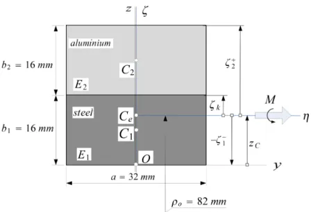
Figure 1.1. Some possible nonhomogeneous symmetric cross-sections.
A class of inhomogeneity (heterogeneity) this thesis aims to deal with is called cross- sectional inhomogeneity. It means that the material parameters, like Young's modulus E and the Poisson ratio ν can be functions of the cross-sectional coordinates η, ζ assuming that the symmetry relations E(η, ζ) = E(−η, ζ) and ν(η, ζ) = ν(−η, ζ) are satised. The material distribution can be continuous, or constant over each segment of the cross-section.
In Figure 1.1 pointCdenotes the geometrical center, andCeis theE-weighted centroid. For circular beams with cross-sectional inhomogeneity, I intend to deal with three mechanical issues as detailed in the forthcoming.
1
1.2. Stresses in curved beams
The mechanical behaviour of curved beams has been a topic of interest since the 19th century. The very rst related source found by the author is a book by Bresse [1]. He managed to establish relations between the displacement eld and the axial force and bending moment. Winkler [2] was the rst to propose a formula for the normal stress distribution in curved beams. Meanwhile, Grashof is known for introducing an equilibrium method for the calculation of the shear stress [3]. The early results and many additional citations are well collected in the scientic works [4,5,6,7].
Curved beams are still subject to intense interest by scientist. On the one hand because of their important role and advantageous properties in various structures and on the other hand due to the spread of nonhomogeneous members.
Well-known formulae for the stress distributions, the deections of homogeneous straight and curved beams under concentrated and distributed loads can nowadays be found in a bunch of scientic works (books, articles, lecture notes) see, e.g. [8,9,10,11,12,13,14,15].
Interestingly, it seems that the relation for the normal stress distribution by Winkler is attributed to Grashof in Hungarian textbooks see, for instance, [8, 12, 13] on contrary to [16] by Timoshenko. The reason for this misuse might be due to the results achieved by Grashof for cylindrical shells.
There are also some recent and at the same time relevant results which are worthy of mentioning here. A common thing of these is the assumption of a linearly elastic, isotropic constitutive equation.
Tolf [17] analytically investigates stresses in bent curved beams made of bre-reinforced plastic. He nds that the homogeneous model approximates the stresses quite well indeed.
Ascione and Fraternali [18] use a penalty-technique for curved laminated Timoshenko beams, including warping eects. They have developed a nite element technique to obtain the stresses. Segura and Armengaud [19] propose simple analytical formulae for the normal and shearing stresses under bending loads. The normal stress distribution due to the bending moment and axial force is hyperbolic over the cross-section. In addition, the authors have extended Bredt's formula for composite curved beams in order to obtain the shear stresses.
Venkatarman and Sankar [20] contribute to the static analysis of straight sandwich beams with functionally graded core using the Euler-Bernoulli hypothesis. Young's modulus varies exponentially over the beam thickness. Aimin [21] determines the shear stresses in curved composite beams after deriving the governing integral equations. In this way not only the equilibrium equations but also the boundary conditions are satised. Ecsedi and Dluhi [22] analyse the static bending problem of nonhomogeneous non-shear deformable circular beams and rings. Daouadji et al. [23] investigate functionally graded straight cantilever beams (Young's modulus varies continuously through the thickness) from the aspect of a stress function approach. Ecsedi and Lengyel [24] consider two-layered elastic circular Euler- Bernoulli beams with weak shear connection (interlayer slip) and provide exact solutions to the displacement and stress elds.
Using the core idea of cross-sectional inhomogeneity [8,25] it is my
Objective 1 to generalize some classical results valid for homogeneous materials in simple closed-form. These investigations would lead to the following results:
Generalization of two elementary relationships (valid for homogeneous curved beams), that provide the normal stress caused by an axial force and a bending moment, for curved beams with cross-sectional inhomogeneity.
Setting up a further formula for computing the shearing stress.
In addition, a formula for the shear correction factor should also be derived.
The new results for the stresses should be compared with nite element (FE) com- putations.
1.3. Stability issues of curved beams
As buckling of beams is a common way of failure in engineering applications, it has been an important subject to investigations for quite a while. The pioneer of this eld is Euler who, in 1757, published his well-known formula for the critical (buckling) load of straight bars under compression [26]. Since then, a vast amount of novel models have been established. These analytical/numerical investigations include in-plane/out-of-plane, static/dynamic, elastic/elasto-plastic stability of shear-deformable/non-shear-deformable shallow/deep circular/sinusoidal/ parabolic homogeneous/heterogeneous isotropic/anisotro- pic 1D/3D curved beams/arches with sti/elastic supports under concentrated/distributed time-independent/dependent loads. A suitable collection of some relevant results can be found in recent textbooks [27,28,29,30].
The foremost models concerning the static elastic stability of curved beams were based on the inextensibility of the centerline see, e.g. article [31] by Hurlbrink, who managed to determine the critical pressure of clamped beams. Then Chwalla and Kollbrunner made a huge progress [32] as they showed that the extensibility of the centerline should be ac- counted, otherwise the mechanical models can signicantly overestimate the critical load.
An extract of the most important results achieved before the 1960s is gathered in book [33]
by Timoshenko.
Stability issues got in the spotlight during the 1960s. Book [34] by Bolotin, among many other topics, is devoted to the dynamic stability of elastic systems involving, e.g.
(curved) beams. In [35], Schreyer and Masur provide exact analytical solution for a xed- xed shallow arch with rectangular cross-section. Papers [36, 37] by DaDeppo are devoted to the determination of the critical load of deep circular beams, which are subjected to a vertical force. Assuming an inextensible centerline, it is shown that quadratic terms should be accounted in the analysis. Papers [38, 39] by Dym are concerned with the buckling and post-buckling behaviour of pinned shallow arches under dead pressure using a continuum model. A summary of these results is also published in book [40]. Thesis [41] by Szeidl uses analytical methods to determine the Green function matrices of extensible pinned and xed circular beams and, moreover, determines not only the natural frequencies but also the critical loads if the beams are subjected to a radial dead load whose Fourier series is known. As regards the dynamic behaviour of curved beams survey papers [6,7,42] provide an adequate collection.
There have also been many attempts to tackle the stability problem using a nite element (FE) algorithm under various assumptions see, e.g. [43,44,45,46]. Although higher-order curvature terms are not included into these models, the authors assume that the membrane strain is a quadratic function of the rotation eld, while the bending moment is linear in terms of the generalized displacements. Dawe [47] approximates deep and shallow arches using the theory of shallow members. More strain-displacement hypotheses are tested (Vlasov, Marguerre) as well as multiple curved elements. A conclusion is that the use of shallow elements for deep arches might result in substantial errors. Fifth-order polynomials seem to provide excellent results even for a sole element. His subsequent work [48] is based on the deep-arch theory for the approximation. Loula et al. [49] use the Hellinger-Reissner variational principle and introduce the so-called mixed Petrov-Galjorkin FEM for shear- deformable circular beams. A benet of this technique is that there is no membrane or shear locking. Flores and Godoy [50] discretise 3D continuums to determine the critical load both for limit point and bifurcation buckling. Pi et al. [51] develop a nonlinear model which is
based on nite rotations. They account for the pre-buckling deformations which according to the authors happen to be signicant.
Palazotto et al. [52, 53] assume large displacements and rotations and compare ve models for the stability of straight and curved beams. Paper [54] by Szabó is devoted, among others, to the issue of how to incorporate the fact that the body considered (a circular ring) can have a rigid body motion into the stability investigations. Rajasekaran [55] deals with the stability and vibrations of curved beams with a new dierential transformation element method: instead of one sixth-order dierential equation the author solves six rst-order equations.
In the open literature from the recent past, interestingly, there can scarcely be found account for elastic supports. However, as structural members are often connected to each other and they provide elastic restraints, it is worth including these eects. The rotational restraints or those obstructing the displacements can hugely aect the critical load [56,57].
Plaut accounts for stiening elastic supports in [58]. Yang and Tong [59] consider horizontal elastic supports and a vertically distributed uniform load when investigating arches with a linear model.
Nowadays, Pi, Bradford and their co-authors have been contributing to the stability of homogeneous (mainly shallow) arches through thoroughly investigating their new geomet- rically nonlinear model. Pi et al. have evaluated it for various loads (distributed, concen- trated) and boundary conditions (pinned, xed, elastic supports, mixed supports, etc.) see [56,57,60,61,62,63,64]. Some of these articles also involve investigations concerning the post-buckling behaviour. The authors have drawn the conclusion that both the pre-buckling deformations and the nonlinearities have substantial eect on the permissible load. Progress has also been made in the dynamic stability of shallow arches [65, 66, 67]. In the previous articles the loading is a sudden concentrated or distributed force. The core idea is based on the method of conservation of energy. It has turned out that the dynamic critical load is always lower than the static.
A common thing of the previously cited works is the assumption of a homogeneous material. Shaee et al. [68], among other topics, study functionally graded (FGM) curved beams from the aspect of in- and out-of-plane buckling behaviour. The linear model leads to an eigenvalue problem. Kim and Chaudhuri [69] consider the post-buckling behaviour of laminated thin shallow arches under a concentrated load at the crown point with the aid of the Rayleigh-Ritz method. The innitesimal rotations are nonlinear as in most of the formerly mentioned articles. Xi et al. [70] assume FGM arches (the material composition can vary in the direction of the thickness) under uniformly distributed radial follower load and geometric nonlinearities to tackle the stability issue. Article [71] by Vo and Thai is devoted to the stability and vibrations of composite beams using a rened shear deformation theory.
Parabolic variation of shear strains through the depth of the beam is assumed. Fraternali et al. [72] have developed a geometrically nonlinear FE model to investigate the stability and post-buckling behaviour of composite curved beams. The rotations and shear strains are moderately large and the material is bimodular. Bateni and Eslami [73] use the same kinematical hypotheses as in [61] but the arch is made of FGM the material composition follows the Voight-rule of mixture.
On the basis of this overview, no examinations have been carried out concerning the stability problem of circular beams under the assumption of cross-sectional inhomogeneity.
Within the frames of what has been written above my Objective 2 is summarized in the following two items.
I intend develop a new nonlinear model for non-strictly shallow curved beams from the principle of virtual work. It is aimed to be more accurate than, e.g. [61,74] and should be applicable to cross-sectional inhomogeneity as well.
I aim to evaluate the new model for pinned-pinned, xed-xed and rotationally re- strained supports provided that the beam is subjected to a central concentrated load at the crown point. This would involve the determination of the critical loads both for symmetric snap-through and antisymmetric bifurcation buckling. At the same time the typical buckling ranges and its endpoints are also sought. Comparison of the results with those available in the literature and with the Abaqus commercial FE software is also an objective.
1.4. Vibrations of curved beams
The rst source (found by the author) in relation with the free vibrations of curved beams is article [75] by Den Hartog, published in 1928. Further notable contributions in the middle of the last century were devoted to this topic in [76,77,78,79]. All these works assume the inextensibility of the centerline.
Szeidl in his PhD thesis [41] investigates how the extensibility of the centerline can aect the free vibrations of planar circular beams under a constant radial load. The applied theory is linear. The author obtains solutions using numerical procedures. One of these is based on the Green function matrix. With this in hand, the related boundary value problem is transformed to a problem governed by Fredholm integral equations. Three important survey papers were devoted to the vibrations of curved beams during the 1980-90s: [6] by Márkus and Nánási, [42] by Laura and Maurizi, and [7] by Chidamparam and Leissa.
Qatu and Elsharkawy provide exact solutions to the free vibrations of laminated deep arches in [80]. Kang et al. [81] determine the frequencies (eigenvalues) for the in-plane and out-of-plane vibrations of circular Timoshenko arches. Both rotatory inertia and shear deformations are accounted. The dierential quadrature method is used to get the solu- tions. Tüfekçi and Arpaci [82] managed to gain exact analytical solutions for the in-plane free harmonic vibrations of circular arches. The authors account for the extensibility of the centerline and also for the transverse shear and rotatory inertia eects. Krishnan and Suresh [83] developed a shear-deformable FE model to tackle the problem. When there is a constant vertical distributed load, article [84] by Huang presents some solutions. Pa- per [85] by Kanga et al. takes point discontinuities, like elastic supports and masses, into account when dealing with the free vibrations. Ecsedi and Dluhi [22] analyse some dynamic features of non-homogeneous simply supported curved beams and closed rings. Here the kinematical hypothesis is formally dierent but mathematically equivalent to that I use in the forthcoming investigations.
Article [86] by Lawther is also worthy of mentioning as it tackles the problem of how a pre-stressed state of a body can inuence its natural frequencies. He concludes that for multi- parameter problems the eigenvalue of the related solution is described by interaction curves in an eigenvalue space and every such eigenvalue solution has an associated eigenvector.
If all points on a curve have the same eigenvector it means that the curve is actually a straight line. Ozturk [87] presents a FE model for the free planar vibrations of curved beams. The model is derived from cantilever beams, which are under a vertical force at the free end by xing it after the deformations. Elastic foundations are taken into account by Çalim [88]. Hajianmaleki and Qatu [89] consider laminated curved beams. Survey paper [90] by the previous two authors reviews the recent past with many citations included.
Kovács [91] deals with the vibrations of layered arches assuming the possibility of both perfect and even imperfect bonding between any two nearby layers. Wu et al. [92] obtain exact solutions (determine the zeros of the frequency determinant) when the curved element carries concentrated elements, including mass moments and inertias. Article [93] by Juna et al. is devoted to the free vibrations of laminated curved beams using the trigonometric shear deformation theory. The dynamic stiness matrix is obtained from the exact solutions
of the related dierential equations. This paper is in fact the sequel of [94] which deals with straight beams. Nowadays, the dynamic behaviour of FGM straight and curved beams are also of increasing interest see, e.g. [95,96,97,98,99].
Overall, in the open literature there are few solutions devoted to the vibrations of beams using the Green function. Here we mention some of these. Szeidl et al. [100] determine the natural frequencies of pinned and xed circular arches under a distributed load using this technique. Kelemen [101] extends the former investigations. She provides the natural frequencies as a function of a constant distributed load. Abu-Hilal [102] investigates the dy- namic response of prismatic damped straight Euler-Bernoulli beams subjected to distributed and concentrated loads. The author obtains exact solutions. Li et al. [103] investigate the forced vibrations of straight (Timoshenko) beams. The beam is under a time harmonic con- centrated load. Damping eects at the ends are taken into account. There are also some further attempts to investigate the dynamic behaviour of structures (response under periodic loads, displacements, etc.). Lueschen and Bergman [104] investigate uniform Timoshenko beams after providing the exact expression of the corresponding Green function. Foda and Abduljabbar [105] and Mehri et al. [106] determine the deections and present parametric studies of a straight beam under the eect of a moving mass. Kukla and Zamojska [107]
deal with the free vibrations of stepped beams. It seems, however, to be an open issue how a central concentrated load aects the in-plane vibrations of heterogeneous circular beams if they are pinned-pinned or xed-xed at the endpoints.
Within the frames of what has been mentioned above
Objective 3 is related to the in-plane vibrations of loaded circular beams with cross- sectional inhomogeneity. In details, my goals are
to derive those boundary value problems which can make it clear how a radial load aects the natural frequencies of pinned and xed beams,
to construct the Green function matrix for pinned-pinned and xed-xed beams by taking into account that the central load at the crown point can either be compressive or tensile (four Green function matrices are to be determined),
to reduce the eigenvalue problems set up for the natural frequencies (which depend on the load) to eigenvalue problems governed by homogeneous Fredholm integral equation systems (four integral equation systems should be established),
to replace these eigenvalue problems with algebraic ones and to solve them numeri- cally,
to clarify how the vertical force at the crown point aects the frequencies of the vibrations (if there is no concentrated force, it is expected to get back the results valid for the free vibrations),
to verify some results by FEM or by experimental studies.
CHAPTER 2
Stresses in heterogeneous circular beams
2.1. Kinematical hypothesis
The investigations are carried out in the orthogonal curvilinear coordinate system that is shown in Figure 2.1. Lagrangian description is applied throughout this thesis. It is assumed that (a) each cross-section is uniform and symmetric with respect to the axisζ [consequently, the beam is symmetric to the coordinate plane (ξ =s, ζ)]; (b) the E-weighted rst moment of the cross-section with respect to the axis η this quantity is denoted byQeη is equal to zero:
Qeη = Z
A
E(η, ζ)ζdA= 0 (2.1.1)
and (c) Young's modulus E and the Poisson ratio ν are functions of the coordinates η, ζ in such a way that E = E(η, ζ) = E(−η, ζ) and ν = ν(η, ζ) = ν(−η, ζ) this distribution is called cross-sectional inhomogeneity [25]. The axis ξ = s intersects the plane of the cross- section in the point Ce, which is referred to as theE-weighted center of the cross-section (in contrast to the point C, which is the geometrical center of the cross-section).
The coordinate line ξ = s is the E-weighted centerline (or centerline in short) of the curved beam and s is the arc coordinate.
For the sake of later considerations we shall introduce the concepts of the E-weighted area (tensile stiness) and moment of inertia (bending stiness) with respect to the axis η:
Ae = Z
A
E(η, ζ) dA , Ieη = Z
A
E(η, ζ)ζ2dA . (2.1.2) These notions have previously been introduced for straight beams in paper [25] by Baksa and Ecsedi.
Figure 2.1. The coordinate system and theE-weighted centerline.
The orthogonal unit vectors eξ(s), eη and eζ(s) of the coordinate lines ξ, η and ζ are shown in Figure 2.1. Let ρo be the constant radius of theE-weighted centerline in the initial conguration. It is easy to check that eξ(s), andeζ(s) satisfy the relations
deξ
ds =−1 ρo
eζ , deζ ds = 1
ρo
eξ and eζ ×eξ=eη =constant. (2.1.3)
7
The symbol×denotes the vector product, while the Hamilton operator∇assumes the form
∇= ρo
ρo+ζ
∂
∂seξ+ ∂
∂ηeη + ∂
∂ζeζ . (2.1.4)
We further assume that (a) the cross-section has a translation and a rigid body rotation about the axisη, i.e. it remains a plane surface during the deformations and (b) the deformed centerline remains perpendicular to the cross-section (Euler-Bernoulli theory). Under these conditions
u=uo+ψoηζeξ =woeζ+ (uo+ψoηζ)eξ (2.1.5) is the displacement eld of the cross-section, in which uo =uoeξ+woeζ and ψ=ψoηeη are the displacement vector and the rotation on the E-weighted centerline, respectively. As is well-known the cross-product
ψ=−1
2(u× ∇) (2.1.6)
yields the rigid body rotation. Thus ψ|ζ=0 =ψoηeη =− 1
2(woeζ + (uo+ψoηζ)eξ)× ρo
ρo+ζ
∂
∂seξ+ ∂
∂ηeη+ ∂
∂ζeζ
ζ=0
=
= 1 2
uo
ρo − dwo ds
+ψoη
eη (2.1.7) is the rotation on the centerline, that is
ψoη = uo
ρo − dwo
ds . (2.1.8a)
It is the only nonzero coordinate in the antisymmetric tensor of innitesimal rotations Ψ: Ψ = 1
2(u◦ ∇ − ∇ ◦u) , ψη =ψη|ζ=0 =ψoη =eξ·Ψ ·eη, ψξ =ψoξ =ψζ =ψoζ = 0.
(2.1.8b) Further, we have the curvature change in the form
dψoη
ds =κo =−d ds
dwo ds − uo
ρo
. (2.1.8c)
With the diadic product
u◦ ∇= [woeζ+ (uo+ψoηζ)eξ]◦ ρo
ρo+ζ
∂
∂seξ+ ∂
∂ηeη+ ∂
∂ζeζ
=
= ρo ρo+ζ
duo ds +wo
ρo +ζdψoη ds
eξ◦eξ+ +ψoηeξ◦eζ+
ρo
ρo+ζ dwo
ds − uo+ζψoη
ρo+ζ
eζ◦eξ+ ((...)) (2.1.9) in hand we get the axial strain in the linearized Green-Lagrange strain tensor EL as
εξ = eξ·EL·eξ=eξ· 1
2(u◦ ∇+∇ ◦u)·eξ =
= ρo ρo+ζ
duo ds + wo
ρo +dψoη ds ζ
= ρo
ρo+ζ (εoξ+ζκo) . (2.1.10) Here
εoξ = εξ|ζ=0 = duo
ds +wo
ρo (2.1.11)
is the axial strain on the E-weighted centerline.
Some so-called E-weighted reduced quantities like the reduced area, rst moment and moment of inertia are dened by the following relations
AeR = Z
A
ρo
ρo+ζE(η, ζ)dA , QeR = Z
A
ρo
ρo+ζE(η, ζ)ζdA , IeR = Z
A
ρo
ρo+ζE(η, ζ)ζ2dA.
(2.1.12) We shall now clarify how these are related to Ae, Qeη andIeη. Using the power series of the fraction ρo/(ρo+ζ) we have
AeR = Z
A
1− ζ
ρo + ζ2 ρ2o −...
E(η, ζ)dA∼= Z
A
E(η, ζ)dA
| {z }
Ae
− 1 ρo
Z
A
E(η, ζ)ζdA
| {z }
Qeη
=
=Ae− Qeη
ρo =Ae, (2.1.13a)
QeR = Z
A
1− ζ
ρo + ζ2 ρ2o −...
ζE(η, ζ)dA∼=
∼= Z
A
ζE(η, ζ)dA
| {z }
Qeη
− 1 ρo
Z
A
ζ2E(η, ζ)dA
| {z }
Ieη
=Qeη− Ieη
ρo =−Ieη
ρo (2.1.13b)
and
IeR = Z
A
1− ζ
ρo + ζ2 ρ2o −...
ζ2E(η, ζ)dA∼=Ieη (2.1.13c) because Qeη = 0 see (2.1.1). For homogeneous beams we shall use the notations AE,QηE and IηE instead ofAe, Qeη and Ieη.
2.2. Formulae for the normal stress distribution
2.2.1. Generalization of the Grashof formula. It is clear that the axial force and the bending moment are
N = Z
A
σξdA , M = Z
A
ζσξdA . (2.2.1)
In the sequel we shall assume that the inequality σξ ση, σζ concerning the normal stresses in the second Piola-Kirchho stress tensorS holds. Thus, equationσξ =E(η, ζ)εξis Hooke's law. Upon substitution of Hooke's law and then equation (2.1.10) into (2.2.1)1 we have
N =εoξ Z
A
ρo
ρo+ζE(η, ζ)dA+κo Z
A
ρo
ρo+ζE(η, ζ)ζdA=εoξAeR+κoQeR . (2.2.2a) As for the bending moment, in a similar way, we obtain
M =εoξ Z
A
ρo
ρo+ζE(η, ζ)ζdA+κo Z
A
ρo
ρo+ζE(η, ζ)ζ2dA =εoξQeR +κoIeR . (2.2.2b) After solving equation system (2.2.2) we get εoξ and κo in terms of the inner axial force N and bending moment M:
εoξ = 1
Q2eR−AeRIeR (M QeR−N IeR) , κo = 1
Q2eR −AeRIeR (N QeR −M AeR) . (2.2.3) Let us now insert these solutions into equation (2.1.10). In this way we get the 'exact' axial strain as a function of N and M in such a way that
εξ = ρo ρo+ζ
1
AeRIeR−Q2eR [(IeR −ζQeR)N −M(QeR−ζAeR)] . (2.2.4)
With the former expression in hand we can rewrite the formula for the normal stress:
σξ =E(η, ζ)εξ =E(η, ζ) ρo ρo+ζ
1
AeRIeR −Q2eR [(IeR−ζQeR)N −M(QeR−ζAeR)] . (2.2.5) In the sequel an attempt is made to simplify (2.2.5). Concerning the denominator, the following approximation holds
AeRIeR
1− Q2eR IeRAeR
'AeRIeR
1− 1 ρ2o
Ieη2 AeRIeR
=AeRIeR
1− 1 ρ2o
Ieη AeR
'AeRIeR (2.2.6) since
1 1 ρ2o
Ieη AeR .
Owing to this result we can equivalently rewrite formula (2.2.4) in the form εξ ≈ ρo
ρo+ζ 1
AeRIeR [(IeR −ζQeR)N−M(QeR−ζAeR)] =
=
1−ζQeR
IeR
ρo
ρo+ζ N AeR +
− QeR
AeRIeR + ζ IeR
ρo
ρo+ζM . (2.2.7) Recalling approximations (2.1.13) one can easily accept the validity of equations
QeR
IeR ' −1 ρo
Ieη
IeR ' −1
ρo , 1 ρo
ρo ρo+ζ
M
AeR ' M
ρoAeR . (2.2.8) Substituting now the last two expressions into (2.2.7) and then the strain into Hooke's law, we arrive at
σξ =E(η, ζ) N
AeR + M
ρoAeR + M IeR
ρo ρo+ζζ
. (2.2.9)
This equation can be considered as the generalization of the Grashof (Winkler) formula, which is valid only for homogeneous curved beams. It can be compared with, e.g. (10.10) in [13]:
σξ = N
A + M ρoA + M
IR
ρo ρo+ζζ
. (2.2.10)
2.2.2. The normal stress under pure bending. English textbooks often contain a formula for the normal stress under the assumption of pure bending see, for instance, equation (4.71) p. 224 in [11]. Our aim is to generalize the cited equation for heterogeneous circular beams. Figure 2.2 displays the cross-section and the geometrical meaning of some notational conventions: ζo is the coordinate of the neutral axis with radiusρo, and the radius of an arbitrary point P on the cross-section with coordinate ζ is r (r = ρo +ζ). For pure bending based on the exact equation (2.2.5)
σξ =E(η, ζ) ρo ρo+ζ
1
AeRIeR −Q2eR (ζAeR−QeR)M (2.2.11) is the stress distribution. We intend to manipulate it into a similar form as published in [11].
The comparison will be carried out on page 12.
As a rst step we shall determine the location of the neutral axis, where σξ = 0. Based on (2.2.11) its location can be obtained from
QeR =ζoAeR , (2.2.12)
Figure 2.2. Some geometrical notations over the cross-section.
or which is the same from equation
QeR = (ρo+ζo−ρo)AeR = (ρo−ρo)AeR =ρoAeR−ρoAeR . (2.2.13) Therefore
ρo = QeR AeR
+ρo (2.2.14)
is the radius sought. Upon substitution of AeR and QeR from (2.1.12) this radius assumes the form
ρo =ρo+ R
AE(η, ζ)ζρrodA R
A ρo
rE(η, ζ)dA = R
AE(η, ζ)ζρrodA+ρ2oR
A E(η,ζ)
r dA
ρoR
A E(η,ζ)
r dA =
=
1 ρo
R
AE(η, ζ)ζρrodA+ρoR
A E(η,ζ)
r dA
R
A E(η,ζ)
r dA =
= R
A E(η,ζ)ζ
r dA+ρoR
A E(η,ζ)
r dA
R
A E(η,ζ)
r dA =
R
A
hE(η,ζ)ζ
r +ρoE(η,ζ) r
i dA R
A E(η,ζ)
r dA =
= R
AE(η, ζ)ζ
r +ρro dA R
A E(η,ζ)
r dA =
R
AE(η, ζ)h
ζ+ρo
ρo+ζ
i dA R
A E(η,ζ)
r dA =
R
AE(η, ζ)dA R
A E(η,ζ)
r dA . If the modulus E is constant the above equation coincides with formula (4.66) in [11].
We proceed with the determination of the normal stress. With equation (2.2.14), the term in parentheses in (2.2.11) can be rewritten:
ζAeR−QeR = (r−ρo)AeR+ρoAeR−ρoAeR = (r−ρo)AeR. (2.2.15) Taking the inequality AeRIeR Q2eR into consideration and substituting back the previous term into equation (2.2.11) we obtain
σξ =E(η, ζ)1 rM ρo
IeR (r−ρo) . (2.2.16)
One ultimate question is how to transform the quotient ρo/IeR into a more favourable form.
All the necessary transformation steps are detailed hereinafter IeR =
Z
A
E(η, ζ)ρo
r ζ2dA= Z
A
E(η, ζ)ρo
ρo+ζ−ρo
r ζdA=
= Z
A
E(η, ζ)ρor−ρo
r ζdA=ρo Z
A
E(η, ζ)ζdA− Z
A
E(η, ζ)ρ2o1
r(r−ρo)dA=
=ρoQeη
| {z }
0
− Z
A
E(η, ζ)ρ2o1
r(r−ρo)dA=−ρ2o Z
A
E(η, ζ)dA+ρ3o Z
A
E(η, ζ) r dA=
=−ρ2oAe+ρ3o Z
A
E(η, ζ)
r dA =Ae ρ3o
ρo −ρ2o
=
=Aeρ2o ρo
ρo −1
=Aeρ2o
−ζo
z }| { ρo−ρo
ρo
=−Ae
ρ2o
ρoζo . (2.2.17) If we introduce the notation e=−ζo and substitute the result obtained into formula (2.2.16) we arrive at the
σξ =E(η, ζ)M r
r−ρo
Ae e (2.2.18)
nal form of the normal stress. This equation is the extension of formula (4.71) p. 224 in [11] for beams with cross-sectional inhomogeneity. The formula cited is
σξ = M r
r−ρo
A e (2.2.19)
if we use our notations and coordinate system.
2.3. Formula for the shear stress
The next goal is to derive closed-form solution for the calculation of the shear stress. Equi- librium equations will be used for this purpose. This approach results in a relatively simple formula, however, it has the drawback that the kinematical equations are not completely satised. The basic concept is well known from the theory of straight beams: we divide a short portion of the beam into two parts and then analyse the equilibrium conditions of one part.
Figure 2.3. The investigated portion of the beam.
Consider Figure 2.3 which shows a nite portion of the curved beam with cross-sectional inhomogeneity. The left cross-section with arc coordinate sB is xed and the coordinate s > sB of the right cross-section is regarded as a parameter. We shall use the following assumptions:
(1) the shear stresses τξ = τηξeη +τζξeζ on the line ζ = ˆζ = constant intersect each other in one point which coincides with the intersection point of the tangents to the contour of the cross-section at ζ = ˆζ =constant. Consequently, τηξ(η) = −τηξ(−η), which means that τηξ(η)is an odd function of η.
(2) The shear stress τζξ is constant if ζ =constant.
(3) The bending moment M and the shear force Vζ are related to each other via equilib- rium condition
dM
ds =−Vζ. (2.3.1)
(4) The normal stress σξ can be calculated from equation (2.2.9), for which, we assume N = 0 there is no axial force in the cross-section.
For calculating the shear stress τζξ let us consider the part of the beam with outlines drawn in thick in Figure 2.3. It is bounded by the marked endfaces A0B, A0, the cylinder with radius ρo+ ˆζ and the lateral surface. By assumption the lateral surface is unloaded.
The equilibrium equation for the considered portion is of the form Z
A0
(σξeξ(ξ) +τξ) dA− Z
A0B
(σξeξ(ξ) +τξ) dA− Z s
sB
ρo+ ˆζ
ρo v(ˆζ)τξζ(ˆζ)eξ(ξ)dξ=0. (2.3.2) If we take into account that the shear stress −τξζ(ˆζ)eξ(s) is constant on the cylindrical surface with radius ρo+ ˆζ, and the fact that
ρo+ ˆζ ρo
v(ˆζ)dξ= dA
is the surface element then it follows that the last integral in (2.3.2) is the resultant of the shear stresses.
Let us dierentiate equation (2.3.2) with respect to s. After that (a) substitute (2.1.3) for the derivatives of the unit vectors eξ and eζ; (b) take into account that (i) the integral over A0B is constant therefore its derivative is zero; (ii) τηξ is an odd function ofη, therefore its integral is zero; (iii) the derivative of an integral with respect to the upper limit is the integrand itself. The former thoughts lead to
Z
A0
dσξ
ds eξdA− Z
A0
σξ
ρoeζdA+ d ds
Z
A0
τηξeηdA
| {z }
=0
+
+ Z
A0
dτζξ
ds eζ +τζξ ρoeξ
dA− ρo+ ˆζ
ρo v(ˆζ)τξζ(ˆζ)eζ(s) =0. If we now dot multiply throughout by eξ we obtain
Z
A0
dσξ ds dA+
Z
A0
τζξ ρo
dA−ρo+ ˆζ ρo
v(ˆζ)τξζ(ˆζ) = 0. (2.3.3) Let emax be the distance between the top of the cross-section and the point Ce. This is always less than ρo for curved beams. The area A0 can be given as the product v(ˆζ)h(ˆζ), where h(ˆζ) is less than emax. Consequently,
Z
A0
τζξ(η, ζ)
ρo dA ' 1
ρoh(ˆζ)v(ˆζ)τξζ(ˆζ), h(ˆζ) ρo 1
is an upper limit for the second integral in (2.3.3). Really, if we take into account that the shear stress is taken on the lineζˆ(instead of being taken at inner points ofA0) we can readily check the validity of the previous statement. On the basis of this estimation, the second term in (2.3.3) can be neglected if we compare it to the third one. Omitting this term results in the equation
Z
A0
dσξ
ds dA= ρo+ ˆζ
ρo v(ˆζ)τξζ(ˆζ) (2.3.4)