2
Molecular and Atomic Beams at Berkeley
W. A. NIERENBERG Institute for Basic Research in Science, University of California, Berkeley, California
I. Introduction
Berkeley is now the home of Professor O. Stern, whose seventieth birthday we are commemorating. This article is a résumé of the data and results presented at the Brookhaven Conference on Molecular Beams (1957) by the present group at Berkeley on the spins and moments of radioactive nuclei of short half-lives. In this introduction it is parti- cularly apropos to present a short history of molecular beam research at Berkeley. In this endeavor, the author is greatly indebted to Pro- fessor L. B. Loeb for much of the material. The first research at Berkeley, using molecular beams, is recorded in a master's thesis of 1926 by Arthur Stanton Adams, entitled "The Reflection of Zinc Atoms from Heated Surfaces." This early research, and the others to be described, were started under the powerful stimulus of the results from the group of workers under Professor Stern. The members of the Department of Physics at Berkeley were greatly impressed and felt that some effort in the same direction should be made. Under the direction of Professor E. E. Hall, then chairman of the department, a thesis was completed in 1927 by Newton S. Herod on "The Distribution of Velo- cities in Metallic Vapor". Except for the thesis, this work was never published. This same field of research was continued with an improved apparatus by Ira F. Zartman (under the direction of Professor Loeb).
Zartman received his Ph.D. in 1930 and published his results in the Phys. Rev. 37, 382 (1931) under the title "The Direct Measurement of Molecular Velocities." Cheng Chuan Ko received his degree in 1933 and published his results in the J. Franklin Institute 217, 173 (1934) under the title "The Heat of Dissociation of B12 Determined by the Method of Molecular Beams." The work of these two scientists has become somewhat of a classic due to the variety and nature of the results obtained. During this period (1929-1930), Professor Stern was
B 9
visiting at Berkeley with the title of Lecturer in Physics and Chemistry.
Shortly thereafter (1931-1932) Professor I. Estermann was Visiting Research Associate and conducted research as an International Fellow of the Rockefeller Foundation. Despite the limited time avail- able, a molecular beam apparatus was constructed, and a measurement of the electric dipole moment of HC1 was made. This was a continua- tion of work started at Hamburg with R. G. J. Fraser, who was then at Cambridge. The results are published in an article with R. G. J.
Fraser: "The Deflection of Molecular Rays in an Electric Field: The Electric Moment of Hydrogen Chloride," / . Chem. Phys. 1, 390 (1933).
This apparatus used a special high-speed pump that was designed by Estermann and H. T. Byck. The work on the pump was published in Rev. Sei. Instr. 3, 482 (1932) and Phys. Rev. 39, 553 (1932) (A). Byck was a National Research Fellow and, in addition, was an Instructor in Physics, 1930-1933.
In December, 1932, E. M. McMillan came to Berkeley from Prince- ton, where he had written his Ph.D. thesis on "Deflections of Beams of HC1 Molecules in a Non-Homogeneous Electric Field" under C. T.
Zahn and, later, E. U. Condon. McMillan, then a National Research Fellow had proposed as a problem the determination of the proton magnetic moment. He hardly started the problem when Stern announced the measurement at Hamburg. This left McMillan un- decided and he changed his field of research with some success. Be- cause of the war and other interests, this field of research was dormant at Berkeley until 1950. About 1951, Professor H. B. Silsbee joined the physics department in order to pursue the subject. A molecular beam apparatus was built and resulted in a thesis (1953) by George Bemski on "The Fluorine Resonance in Molecular Beams".1 At the same time, the Engineering Research Institute started research, under the aegis of Professor Estermann, on the scattering of molecules from a surface.
Dr. F. Hurlbut obtained his Ph.D. in this research and is still actively connected with it. Professor Estermann is still actively associated with this research and spent the summers of 1948, 1950, and 1957 with the Institute. In 1951, the group at Berkeley began research on short- lived radioactive species. Since other groups elsewhere made excellent progress on neutron-activated isotopes, it was decided to push forward on cyclotron-induced activities. These were more difficult, owing to the low production, but offered more isotopes for study. A zero-moment apparatus was started in 1951, and J. P. Hobson and J. C. Hubbs wrote their doctoral theses2 in 1953 on the spin and moment of 4.8 hr Rb81. With the special techniques developed for producing, detecting, and collecting the isotopes well in hand, the zero-moment
M O L E C U L A R AND ATOMIC BEAMS AT BERKELEY 11 equipment was converted to a Zacharias-Rabi "flop-in" apparatus in the fall of 1955, and the first measurements were made in February, 1956. R. J . Sunderland wrote his thesis (1956) on the radioactive rubidium isotopes,3 and H. A. Shugart received his Ph.D. (1957) with a thesis based on the cesium isotopes.4 Because of the special health hazards, there are now two other apparatuses operating, one primarily for transuranic elements and one for the radiohalogens. J . L. Wor- cester received his Ph.D. in 1957 for work on the gallium isotopes,5 and G. O. Brink received his in 1956 for work on the thallium isotopes.6 To date, the spins of 36 isotopes have been observed, three earlier by other groups or other methods. The hyperfine structures of approxi- mately half of these have been determined, and most of the remainder will yield in time. Much is still to be done. In addition to new spin measurements, such parameters as the hyperfine anomalies will be measured.
The remainder of this article will be in three sections. The first section will deal with those atoms in / = \ ground states, such as Rb, Cs, Cu, Au, Ag, etc., for which the beam technique is essentially the same. The second section will treat those atoms which are available in quantity in both 2Pf and 2P% states, such as I, Br, and Ga. The third section will be devoted to Pu239, which is the first transuranic investigation to be completed by atomic beams.7 This account cannot be complete in itself, and the reader is referred to several earlier works on specific details of the methods employed.8
Π. The 2Sh Ground States
There are many reasons for choosing 2S± atoms for initial research in this field. First, this group includes the alkalis whose beam-forming properties are known to be particularly facile and for which the normali- zation problem is particularly simple due to the ease in detecting the carrier isotope. Second, the intensity of a resonance line goes as 2/(27 + 1) ( 2 / +1) and is greatest for / = \ {J = 0 is, of course, exclu- ded), where / i s the nuclear spin a n d / is the electronic angular momen- tum. Third, the relative simplicity of the Hamiltonian for / = ^ makes the problem of determining the Δν (hyperfine separation) easier and reduces the difficulty encountered with multiple quantum transi- tions. Fourth, for these states, gj Ξ —2, thus leading to a large deflec- tion for the "flop-in" states.8»9 It is not surprising, therefore, that most radioactive spin determinations have been done for these atoms. Obvi- ously, it is not possible to treat in detail all twenty-five radioactive spins that have been observed on J = J atoms in Berkeley. Therefore, the discussion will be limited to the six isotopes of gold, Au191, Au192, Au193,
12 W . A . N I E R E N B E R G
Au*94, Au*»·, and Au"», whose half-lives are 3 h, 4.8 h, 17 h, 39 h, 5.6 d, and 2.7 d, respectively. Results on these isotopes were presented for the first time by H. A. Shugart at the 3rd Brookhaven Conference on Atomic Beams, October 31, and November 1, 1957. (Au198 had previously been measured by the group at Princeton.) In addition, some discussion of the cyclotron-produced Cs isotopes will be included to illustrate some problems not encountered with the Au isotopes and to illuminate the procedure for finding Δν. The isotopes of Au just mentioned can be produced by bombardment of alphas on Ir or by protons or deuterons on Pt. The plethora of isotopes produced,10 plus the similarity of half-lives for possibly coincident spins, made it desir- able to have two methods of producing the isotopes for possible differ- ential determinations. There are two stable isotopes of iridium, Ir191 (38.5%) and Ir193 (61.5%). Platinum has six stable isotopes, but only four are in appreciable abundance for Au production purposes. They are Pt*94 (33%), Pt"* (34%), P t « · (25%), and Pt*98 (7%). The vari- ous isotopes have been produced as follows.
Au191: (α, 4Λ) on Ir"*.
Au*92: (a, 3Λ) on IrWi.
Au193: (a, In) on Ir191, and (a, 4n) on Ir*93.
Au194: (a, n) on Ir*9*, (a, 3n) on Ir*93, and (p9 n) on Pt194.
Au195: (p, n) on Pt195, and (a, In) on Ir193 (the latter was not ob- served in these experiments).
Au1 9 6 (14 h) : (a, n) on Ir193 and (/>, ή) on Pt196 (this isotope was not observed in these experiments, and it is problematical whether any appreciable quantity was made).
Au196 (5.6 d) : (d, In) on Pt196, and (a, n) on Ir193 (the latter was not observed in these experiments).
Au*98 (2.7 d) : (p, n) on Pt198 and (d, In) on Pt*98.
From the very first run, resonances corresponding to approximately the correct number were observed but, because of near coincidences, it was necessary to analyze the decay of the resonance very carefully to ascertain the degree of enrichment of the appropriate isotopes. No chemistry is reasonably possible with Ir as the target material, since it is extremely difficult to put into solution. Fortunately this is a situa- tion where the Au can be directly evaporated from the Ir. The Ir foil is precut, before bombardment, into pieces sufficiently small to fit an atomic beam oven. The oven is heated to a temperature below the melting point of Ir, and a very steady, useful beam of Au ensues. In one run the beam was held reasonably constant for eight hours, and the Ir was in condition to be reused for bombardment. The beam itself was collected on sulfur-coated buttons and counted on the now
MOLECULAR AND ATOMIC BEAMS AT BERKELEY 13 conventional x-ray counters.3 The normalization of the beam was ac- complished by taking samples regularly with the stop-wire removed.
Similarly it was possible to evaporate the Au from the Pt targets, and several measurements were made in this manner. However, the beam was decidedly unsteady, and most of the runs were undertaken with samples that were chemically separated by the standard technique using ethyl acetate. A brief description of the recipe used is as follows. The Pt target is dissolved in aqua regia, and carrier Au is added in the amount necessary to obtain a beam of given intensity for the needed running time. The solution is boiled to dryness and redissolved in 6N HC1.
Ethyl acetate is added, the AuClß goes immediately to the ethyl acetate phase, and the HC1 is drawn off from the bottom. The ethyl acetate is evaporated, the residue is redissolved in 3N HC1, and the Au is re- duced by bubbling SO2 through the solution. The gold is separated by centrifugation or coagulation by boiling, and the solid gold is trans- ferred to the oven which is made of Ta. The oven is heated by electron bombardment until a beam of about 100 counts per minute per minute of exposure is obtained.
The resonance field is calibrated with a Rb beam from a permanently situated oven. The Au oven can be moved to one side for field calibra- tion and returned for beam work. One major difficulty that occurred was the abnormally wide variations in Δν for the various Au isotopes.
The Δν of Au19** is about 22,000 Mc/sec, and that of Au*92 (4.8 h) is about 400 Mc/sec, with the other isotopes more or less uniformly distri- buted between these limits. In fact, the Au192 moment is 0.008 nuclear magnetons, which is very small. This means that quadratic shifts from the Zeeman frequencies occur more readily; great care has to be exer- cised in choosing C-field values and more complete resonance curves are required than is usually the case in spin determinations. The beam collection for Au is fortunately simple, since the standard sulfur surfaces work very well. (The halogens, however, offer great difficulty and, finally, freshly evaporated Ag surfaces were decided on as being the most reliable and efficient of all the ones tried.)
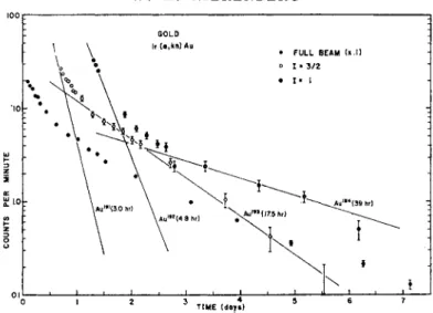
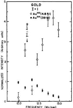
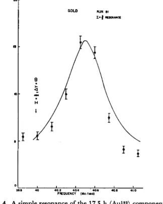
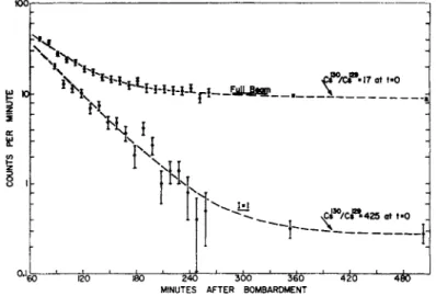
Figure 1 is an example of a full beam compared to the decays of re- sonances observed for spin 1 and spin § for Au. The assignments are made by decay. Fig. 2 is an example of the 1=1 resonance, showing the two components of the spin. The 4.8 h Au192 has a large quadratic shift and has been shifted away from the resonance. Fig. 3 is a reson- ance of the 7 = 1 , counted at different times, showing the two com- ponents. Fig. 4 is a resonance of the 17.5 h component (I = f). This data and other similar runs yielded the values for the Au isotopes given in the table at the end of the article.
14 W . A . N I E R E N B E R G
Id I H Γ
* L
Fig. 1. The decay of two resonances observed in an experiment on Au isotopes.
The resonances correspond to / = 1, and I = ^.
N K 4-
RUN78 I « I RESONANCE
8
<
Hi u
Ιβ.Ο l »0
FREQUENCY ( M C / M C)
Fig. 2. A sweep of the spin 1 = 1 region showing the two spin components.
Point B decayed with a pure 39 h half-life; point A decayed with a 4.8 h half- life. The Au192 shows a large quadratic shift at this low field.
M O L E C U L A R A N D A T O M I C BEAMS AT B E R K E L E Y 15 5r
12.0 12.5 13.0 FREQUENCY (Mc/sec)
Fig. 3. / = 1 resonance curve, analytically resolved into two components of 4.8 h and 39 h half-lives. The Au192 shows a large quadratic shift due to its small
magnetic moment.
The research on the Cs isotopes, although similar in many ways to that on the Au, is sufficiently different in detail to warrant an abbre- viated account emphasizing these differences. The isotopes studied in some detail were Csi273 C s ^ , Cs^o, and Csi32. in addition, the Csisi spin was remeasured. There is only one stable isotope of I, namely I127. The (a, kn) reaction was used on Bal2 to make Cs12? (6.2 h), Csi29 (31 h), and Csi30 (3 0 m) . The (p, n) reaction was employed on gaseous Xe to make Cs129, Csisi, and Cs1»2. The isotopes of Xe involved are Xei29 (29%), Xei3i (21o/0), a nd Xei32 (27%), respectively. The chemistry used with the Bal2 target is very interesting and exemplifies the special problems of this research. If Csl were used for the target, there would be too much carrier for the maximum allowed running time of the beam. Furthermore, the Bal2 is more stable and packs more I atoms into the given range of the alpha particles. The chemistry then consists in dissolving the Bal2 in water with the required amount of Csl carrier and precipitating the Ba with ammonium carbonate.
The N H J and (NH4)2C03 are differentially sublimed and the Csl
residue is redissolved in a few drops of water and transferred into and dried in the oven, which is made of iron. Ca is then added, and the usual Cs beam is produced. The Xe is in a special target about 40 cm long and 5 x 10 cm in cross section which has a thin aluminium window at one end. After bombardment, the Xe is frozen out onto a liquid N2 trap, and a controlled amount of water with carrier Csl is sucked in, after which the whole assembly is agitated. The residue is reduced in
RUN 81 I · I RESONANCE
40.2 40.4 4 0« FREQUENCY (Me / M C)
Fig. 4. A simple resonance of the 17.5 h (Au193) component.
volume and transferred and dried into the oven as before. The (a, kn) research was first done at a time when the 30 m Cs130 was gone. Only one resonance was observed and that was for a spin of \. For equivalent exposures the initial counting rate on the spin J resonance was 100 ± 1.5 and on all other resonance buttons, averaged in arbitrary units, 1.5.
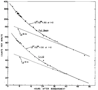
This is a typical signal-to-noise ratio for spin | . Fig. 5 is the decay of the spin \ sample and that of the full beam sample. They are quite similar, and the inference is that both components have the same spin.
Fig. 6 is the decay of another run where the isotopes are produced by a thinner target to enhance the (a, 4w) reaction. Both the resonance decay and the main beam decay show the same relative increase in the
MOLECULAR AND ATOMIC BEAMS AT BERKELEY 17
20O-
CE 100}-
V
-Cs /Cs = .25 at t=0 Y ^ * \
. ~ ^ ? · \ .30att«0 T ^ h r .
\
16 24 32 40 HOURS AFTER BOMBARDMENT
48
Fig. 5. The radioactive decay of a straight-through beam sample and an / = -i resonance sample. This was the only spin sample that showed an appreciable counting rate. Both curves are alike within experimental error,
indicating that Cs127 and Cs129 both have I = £.
Y
Y ^Cs'/Cs «1.50 at fO
V\
».Full Beom- Cs /Cs «1.50 ot t=0
T = 3 l hr ~ ^
HOURS AFTER BOMBARDMENT
Fig. 6. Same as Fig. 5. The isotopes are produced by bombardment on a thin sample. The (a, An) reaction is clearly enhanced relative to the (a, 2n) reaction.
Both curves are still parallel, indicating that both isotopes have / = J.
18 W . A . N I E R E N B E R G
fast component. In order to measure the spin of the 30 m Cs130, a short bombardment was obtained and the same chemistry performed.
It was done very quickly and inefficiently, however. The signal on spin 1 was 100 ± 13, compared to an average of about 10 ± 5 on spins 0, 2, 3, and 4, in each of two runs. The signal-to-noise ratio was sufficiently good that it was possible to carry the resonance to high enough fields to measure the Δν and, therefore, the nuclear magnetic moment, despite the short half-life of the material. Fig. 7 shows the decay of the full beam compared to that of the resonance.
£ »r
<Ç?°/dP'\7a\ t»0
K
\u
Xs^/Cs*·«^ at t-0
240
MINUTES 300 360
AFTER BOMBARDMENT -4*Γ
Fig. 7. The radioactive decay of a spin 1 sample. The isotope separation is clear and the I = \ must be assigned to 30 m Cs130.
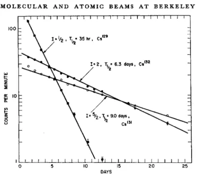
Figure 8 is the result of a resonance search of a run on the (p, n) reac- tion on Xe. Three clear resonances were observed, and they decayed with half-lives appropriate to Cs129, Cs131, and Cs132. The correspond- ing spins are f, f, and 2. The full beam decay is composite compared to the excellent straight lines of the three resonances. This isotope separation alone is independent confirmation of the resonances, as well as that afforded by the intensity factors. It is very gratifying to obtain agreement on the Cs129 spin after production by two independent means.
It is also gratifying to check the Cs131 by an independent production and detection scheme. Originally the spin of Cs131 was detected mass- spectroscopically.11
The Av's of these isotopes were determined by direct application of the Breit-Rabi formula to the flop-in transition. They are too large for a search for the &F = ± 1 transition at the precision required or attain- able. In all cases the Fermi-Segrè formula was used to calculate the
M O L E C U L A R AND ATOMIC BEAMS AT BERKELEY 19
100 h
z g 10
O
Ί—I—I—Γ~Τ~1—I Γ~Γ~Ι Γ Ί — 1 1 1 1 — I — Γ Ί — Γ Π — I Γ
I » '/2 , Τ. « 35 hr, Cs1
1*2, T. = 6.3 doys, Ce'0
l I I I I t I t I I I I * l I I I I I I I I I I I I 10 15
DAYS
25
Fig. 8. Spin £, 2, and f resonances in the (p, n) on Xe reaction. The background effect is so low that each decay curve is a straight line.
ratio of the gi of the unknown to the gi of the comparing isotope, given the respective Av's. The two equations are
Δν = and
[v+{μφΗΙΚ)][{ - yogjHIh) - y]
v+ frogjHlh(2I+1)] + [2/^////A(2/+1)]' i I M 2 / i + l ) , ,
>S ' Δνι(2/+1)Ι Αι'
(1)
(2) The latter relation is good to better than 1 % for Cs, and the subscripted quantities refer to Cs133 for which they are well known. Both formulas can be combined into a very useful form.
2C
where
A
B+(&-4ACf
2ΙμοΗ(2Ι1 + 1)§Ιι
ΑΔΙΊ(2/+1)2 '
(3a)
(3b)
B = V + WgjH
H 1 Vv\, (3c) A(2/+l) ΑΔνι(2/+1)
and
C = v\{^gjH\h)+v\. (3d)
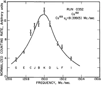
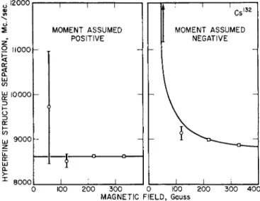
This unusual form of the solution to the quadratic equation is needed to prevent loss of significant figures in the final answer for Δν due to the smallness of A. Fig. 9 is a resonance fit by least squares analysis to a typical Cs132 resonance. Fig. 10 shows the method used to deter- mine the sign of gj. Δν is computed for each resonance, assuming first that gi > 0, and second that gi < 0. The two values are denoted by
Δν+ and Δν~. Both values are plotted versus H and the set of Ay's belonging to the ultimately correct sign of gi will fall along a horizontal line, while the set belonging to the incorrect sign of gi will fall along a theoretically predictable curve. Since gi > 0 for Cs132, the data shows a very good fit under these assumptions.
RUN 0352 C sl 3 3v =81.399(5) Ma/sec.
129.6 129.8 130.0 130.2
FREQUENCY, Mc./sec.
130.4 130.6
Fig. 9. A resonance curve of Cs132 with Cs133 as the calibrating substance. The curve is a least squares fit. The uncertainty in the position of the resonance center due to counting statistics is much less than the half to one-quarter line
width uncertainty that is used for calculating Av.
M O L E C U L A R AND ATOMIC BEAMS AT BERKELEY 21
• 12000
2
2 ilooo 55 en
UJ CO
ω 10000
\-O
co
ω 9000
8000
MOMENT ASSUMED POSITIVE
Cs,0<
MOMENT ASSUMED NEGATIVE
100 2 0 0 3 0 0 0 100 2 0 0
MAGNETIC F I E L D , Gauss
3 0 0 4 0 0
Fig. 10. Consistency test for determining the sign of gi. Gs132 is the substance.
The graph on the left displays the Δι/'s obtained from measurements at different fields, assuming gi>0. The values fit a horizontal straight line. The graph on the right shows the Δ Α calculated for gi<0 along with the theoretical solid line which assumes that the assignment gi<0 is incorrect. The conclusion is
t h a t £ / > 0 .
III. The 2Pi Atoms*2
The gallium, bromine, and iodine isotopes fall into this category of atoms that can be studied in the 2P t state. The isotopes that have been successfully studied at Berkeley are Ga66, Ga6?, Ga6», Br82, μ23? ji24>
and I131, whose half-lives are 9.4 h, 78 h, 68 m, 36 h, 13 h, 4.5 d, and 8.1 d, respectively. All are cyclotron-produced, except the Br82 and I131. The first is produced by (n, γ) pile reactions; the second is pro- duced as a fission product. The Ga isotopes were produced by (a, kn) reactions on Cu63 (69%) and Cu65 (31%) on the Crocker 60-in. cyclo- tron.13 Attempts to distill the Ga directly out of the Cu target, a method which succeeded with Au out of Ir, Ag out of Rh, and Cu out of Co, failed completely. Plating the Ga on Pt foils, which were crumpled into an oven, also failed to yield a beam. The only success was achieved with a chemistry that resulted in pure Ga in a carbon oven. Ovens of other materials, such as Fe and Ta, failed. The final procedure in- volved the plating of the radiogallium and carrier onto a 0.004-in. Pt wire, which protruded i in. from a pyrex tube. The Ga will often coalesce into globules, particularly under the influence of a warm, dilute
HC1 bath. The globule can be shaken off into the carbon oven or scraped directly in. Any Cu that passes the chemistry complicates the procedure and an abbreviated description is as follows.
The Cu target is dissolved in about 15 cc of ION HNO3 with the carrier Ga, and the solution is boiled to reduce the volume. About 60 cc of 6N HC1 saturated with ether and 50 cc of ethyl ether are added, and the gallium chloride is ether-extracted. The ether is washed several additional times with 6N HC1 to remove the last traces of the Cu. The GaCl3 is extracted with 15 cc of H2O, and NaOH is added until the Ga precipitates as Ga(OH)3. The Ga(OH)3 is centrifuged and redissolved in the smallest possible amount of concentrated NaOH; then two platinum electrodes are introduced, and the plating can commence as described above. In 15 minutes about 50% of the activity is re- covered. The plating then slows down, and 75% in one hour was considered good efficiency.
The Br82 was produced by (w, γ) on Br81 (49%). I123 and I124 are produced14 by (a, kn) reactions on Sb*2* (57%) and Sb123 (43%).
Chemistry was required in all cases, and it turned out to be unexpec- tedly difficult. It was necessary to prepare the halogen in gaseous form so that it could enter the discharge tube at a carefully regulated rate.
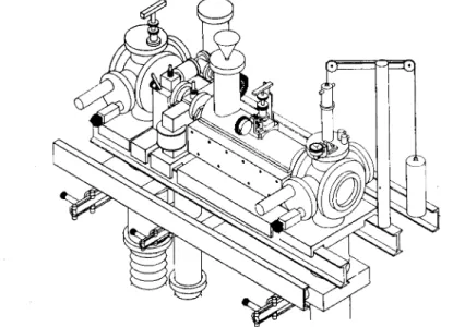
The discharge tube turned out to be singularly efficient. When opera- ting properly, the Stern-Gerlach fields of the apparatus threw out more than 95% of the beam, indicating that only a small fraction of the diatomic molecules were left in the χΣο state. If it is assumed that the deflected component is atomic, then an efficiency of about 95% in atom-making is indicated. Fig. 11 is a drawing of the discharge tube and underneath is a circuit diagram of the regulator. The apparatus is somewhat novel in that it is an "inside out" apparatus. All magnets and windings are completely outside the vacuum. Fig. 12 is a perspec- tive drawing of the apparatus. For safety reasons a glove box surrounds the source end of the apparatus. In all of these experiments, as with the Au isotopes, an auxiliary alkali oven is maintained for field calibration.
All of the apparatuses in Berkeley, except one, are of the asymmetric type, in that the ^4-focusing field is very small compared to the 2?-focusing field.
The I131 comes in the form of Nal from Oak Ridge. Iodine is pre- cipitated by the addition of NaNC>2 and H2SO4 and the iodine extrac- ted into CS2. 200 to 300 mg of I2 are added to the solvent and the CS2 is evaporated off under vacuum. The I123 and I124 are obtained by first dissolving the Sb metal in concentrated HC1 with a few drops of H2C>2and a few mg of Nal carrier. The solution is neutralized with NaOH and the heavy precipitate of SbOCl filtered off; the I is again precipitated
M O L E C U L A R A N D ATOMIC BEAMS AT BERKELEY
AOUADAG COAT
23
^ 0 0 QUARTZ> I ^SUT
x:
-NICKEL ELECTRODE
τ^.
jh— »KOVAR SEALS7
R F DISCHARGE TUBE- h o o n o o o r * -
L
450 Kc /K RF SOURCE Q v )
*
DISCHARGE STABILIZER
Fig. 11. The schematic of a simple discharge tube for dissociating the halogens.
The circuit shown is an excellent regulator for the discharge.
Fig· 12. A perspective view of the halogen apparatus. It is "inside out" in that the magnets and windings are all outside the vacuum. It is hoped that the
radioactive cleanup problem will be less serious with this apparatus,
W . A . N I E R E N B E R G
and extracted from the filtrate by the technique used above. The pro- cedure for Br is different. Br82 is obtained in the form of KBr powder.6 The Br is liberated by heating the KBr with concentrated H2SO4 and Μηθ2· The Br2 is carried over to a liquid-nitrogen-cooled flask with a stream of He. The Br is subsequently evaporated under vacuum to another nitrogen-cooled flask containing P2O5 and thence to a third flask which is used as an oven vial. Br76 and Br77 are obtained by dis- solving the As in Caro's acid with the required amount of Br carrier.
The procedure then follows as above. In all cases the flask containing the liquid or solid is attached directly to the source. The higher vapor pressure of Br necessitates the inclusion of a slow leak.
0ZP 3 / 2 Pl/2 SPIN
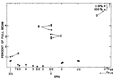
Fig. 13. Spin search involving Gaee and Ga67. The points at D correspond to 7 = 0, 2Ps. They are about 10 % of the full beam. (Fig. 16 is the decay of one of these points.) The points B are the / + and / - of 2Pg, / = f, which are accidentally together at low fields. The points C are the I = 0, 2P%, points. B and C were resolved from the resonance by decay analysis (Fig. 15). The point A is 2P^9 I = f, it is above background and is resolvable by decay analysis.
Figure 13 is a survey of several spin searches for Ga66 and Ga67;
2P| and 2P± resonances are shown for both isotopes. Fig. 14 is a decay of the main beam sample and a spin f sample. Fig. 15 is a decay of the spin 0 sample for Ga66. Fig. 16 is an example of a § resonance at a field where the quadratic shift for the two components just begins to separate the two transitions that have a common gp. Figs. 17 and 18a,b are similar displays of spin searches for I123 and I124, and an I131 resonance;
and Fig. 19 is an example of a resonance seen in I123 ( / - transition) showing a quadratic shift.
MOLECULAR AND ATOMIC BEAMS AT BERKELEY 25
1000, , ■ , i r- —r~
40 60 80 HOURS AFTER BOMBARDMENT
Fig. 14. The decay of a normal beam sample and the decay of the resonances B and C of Fig. 13. Both components are present as they should be, approxi- mately the same as in the full beam. The 2Pi, / = 0, and 2Pg, / = f, reso-
nance conditions are accidentally the same.
20 49 6Ö~
HOURS AFTER BOMBARDMENT
Fig. 15. The decay of a resonance from the D group of Fig. 13. It is pure Gae e as it should be.
c
26 W . A . N I E R E N B E R G
12.500 13000
FREQUENCY (Mc)
Fig. 16. The decay of a 2P§, / = f, resonance (like B of Fig. 13) at a field where the quadratic splitting is appreciable compared to the line widths. The/+ and
/ - levels, which had previously been together, are now just split.
eor
coSOh
J·
IODINE SPIN SEARCH
APPROXIMATE LINE WIDTH · l30Kc>+||+
I
_ 1 _
Spin Vet"
Î | | | IK | j I FREQUENCY (Met) |
18.0
Fig. 17. Spin search for I123 and I123.
MOLECULAR AND ATOMIC BEAMS AT BERKELEY 27
8
IOl·
4~
I 7.2 (+) RESONANCE l ^s =5 Mc/sec
I NOMINAL CENTER
7.8 7.9 8.0 8.1 8.2 FREQUENCY, Mc/sec
Fig. 18a. Resonance (/+) for I1
I— Z
8
1 7/2 (-) RESONANCE Vcs =5 Mc/^ec
5.2 5.3 5.4 5.5 FREQUENCY, Mc/sec
— I MACHINE BACKGROUND
Fig. 18b. Resonance (/-) for I131.
28 W . A . N I E R E N B E R G
i/cs· 10 Mc/sec
FREQUENCY (Mc/ac)
Fig. 19. Quadratic Shift in I123 (/-).
The Hamiltonian, in units of sec-1, used to analyze results on Ga and the halogens is
H= aIJ +
2 / ( 2 7 -1 ) / ( 2 7 - n [3(J.J)» + K Z . J ) - / ( / + l ) / C / + l ) ] - (4)
a is the magnetic dipole interaction in sec-1; b is the quadrupole inter- action constant in sec-1; μο is the Bohr magneton; gj is the atomic ground state ^-factor and is approximtely — |, although the best avail- able precise value is actually used for each isotope; gi is the nuclear
^-factor and is of order 1/2000. The octupole term is not included.
It is presumed to be too small for the sensitivity obtained so far with radioactive species. Fig. 20 is the Breit-Rabi diagram for / = f, where the levels are shown for a > 0 and \b\ sufficiently small so that the zero- field order is normal; the highest F level is highest in energy and the remaining F levels are in the order of decreasing F. For this case, there are just two "flop-in" transitions that are observable. Under some circumstances (relative values of bja)9 the order level in zero magnetic field can be seriously changed from the above arrangement, and it is sometimes possible to observe three "flop-in" transitions. The order of
M O L E C U L A R AND ATOMIC BEAMS AT BERKELEY 29
I * J= 3 / 2 3 3/2
2 1/2 I -1/2 0 -3/2
-2 -3/2 -I -1/2 0 1/2
1 3/2 m, 3 / 2
2 3/2 0 -1/2 1/2 -I -3/2
1/2
3 - 3 / 2
--I 1/22-1'2 - 3 / 2 3 / Z 0 3/2
Fig. 20. The Breit-Rabi diagram for / = f, / = f. The frequencies "A" and
"b" are the normally observed "flop-in" transitions. Another one is possible if the order level is changed due to a large quadrupole-dipole moment coupling
ratio.
the levels depends upon the magnitude and sign of the quantity ξ = b\a.
Tables 1 and 2 are reasonably concise statements of these level arrange- ments versus the quantity ξ.
TABLE 1
THE ORDER OF THE ZERO FIELD LEVELS AS A FUNCTION OF b/a. / > 1.
-oo 4/(27-1)
2 7 - 3 -27 2/(27-1) 2/(2/ - 1 oo
The headings are functions of/for / = | . The columns are values of i, where I+i and the vertical order indicates the arrangement of F levels in energy in zero fields. If ξ has a value between any two adjacent headings, the order of levels is given as indicated in the column between
these headings, where the number in the table is to be added to / to give F. If a > 0, the given upper F value lies highest, if a < 0, the given upper F value lies lowest. If / = f, the most left-hand arrange- ment does not appear. If / = 1, this table does not apply.
TABLE 2
T H E ORDER OF THE ZERO FIELD LEVELS AS A FUNCTION OF b/a. 1 = 1 .
—oo ψ —2 ψ § Ψ 4 ψ ο ο
1 ff
5 ί
X
5 2
1 3 2
1
1 f
This table is the same as Table 1 but for / = 1. The entries here are the actual F-values.
The hyperfine constants a and b have been evaluated for several of these isotopes by observing the two possible transitions for various values of the field including values that correspond to appreciable shifts of the observed resonances from the Zeeman resonance. It can be shown that, given a limited amount of material, the most conservative procedure for evaluating a and b to a given accuracy is to increase the frequency in successive steps so that at each step only about five samples are needed to cover a given frequency region. In principle only about 50 resonance points are needed to obtain the hyperfine constants to a percent or so.
In practice this method works very well for 2Sx states and usually the precision obtained is sufficient to determine the sign of gi as well. The method is excellent for the 2Pt states, but the difficulty in interpreting the results, to obtain the most reliable answer from the smallest amount of data is principally mathematical. First, there are two constants to be determined, a and b, and a least squares procedure is called for to fit say, 10 resonances distributed between two different lines. This is made complicated by the fact that no useful explicit formula is avail- able, giving these frequencies as a function of a, b, and H. If the fre- quency of the upper transition is denoted b y /+ (by upper is meant the transitions between levels of the largest F value in the normal order) and that of the lower by/-, it is known that/+ is the difference between a root of a secular equation of the third degree and one of the second, a n d /- is the difference between a root of a secular equation of the fourth degree and one of the third. The least square procedure15 adopted is necessarily a trial and error procedure which converges
MOLECULAR AND ATOMIC BEAMS AT BERKELEY 31 most rapidly to the correct values of a and b and gives the errors in a and b as well as the weighted sum of the squares of the residuals. The last part, when divided by n —2 where n is the number of observations, is useful in determining the sign of gi by consistency. This procedure will be described later and it will be seen that it involves the calculation of the energy levels with respect to a, b, and H and all the derivatives of these levels with respect to these parameters up to the second degree.
A numerical procedure is therefore needed for calculating these quan- tities. Furthermore, these procedures should, if possible, be generaliz-
An an., o
\ a p o
v
A p d p . ,ap_ \ a3 o o a3V iA3a2
/ A - n - t - D Oia2rA2aL
o! o !a,i'Ä,"
! I Ί ■
D, -D,
Fig. 21. Schematic of a typical M-matrix in F, M representation in atomic beam research.
able to arbitrary J and be convenient for electronic digital computers, such as the IBM 650 and 704, both of which have been used. The fol- lowing method of handling the matrices seemed the most useful, and it is based on the observation that all the matrices treated in atomic beams have a uniformly simple form. If an Fy MF representation is used, the entire Hamiltonian degenerates into submatrices of constant MF values. These matrices are Hermitian (in fact can be put into real symmetric form) and have the special property that all elements which are not on the diagonal, or not one off the diagonal, are zero.
Fig. 21 is a schematic of such a matrix. Let Dn be the value of the determinant of the entire matrix, D\ be the determinant formed by including the lower right-hand element Α^ Ό% the second-order deter- minant that includes A\ and A% as well as the diagonal elements, etc., as shown on the figure. Then a simple recursion relation is
Dp = ApDp_i—\ap_i\2Dp__2, (5)
with the boundary condition that Z>o = 1, D-\ = 0. If x is subtracted from the diagonal matrix elements, the determinant so obtained (the indicial equation) is evaluated by the following difference equation:
Dv = (Ap-x)Dp_i-\ap_i\2Dp_2, (6) and the derivative of the indicial equation with respect to x is
!^L =
{Ap-
x)^ _ | ^ | 2
dJ±± _
D (7) ox ox oxwith the boundary conditions BDo/dx = 0, dD_i[dx = 0. Using New- ton's method, any desired eigenvalue of the matrix can be found by choosing a close trial value and correcting with —Dpj{dDpjdx). This is iterated to the desired accuracy. Usually the zero-field root is chosen as a starting point, and successive roots are computed by incre- menting H. There is no possibility of the method failing for inter- mediate H values because the "no M-cross rule" prevents levels in a given MF matrix from crossing and giving double roots. Higher deri- vatives and derivatives with respect to other quantities obey very similar difference equations and are therefore very easily evaluated.
Fortunately the problem can be put in dimensionless form as follows.
— = l^J + ξυρ Jz IZy
a ha ha
where Op is the coefficient of b in Eq. (4). If v+ = f+ja and v~=f-ja correspond to the dimensionless eigenvalues Xi of ^f/α, such that
„+ = Xl+-x2+, (8)
v-—X1-—X2-i
then tables of x% can be and have been prepared at very low cost, which are universally useful. They are used by recognizing that
/+ _ r. SWH
J-1- observed — J ;;—>
h (9)
gj->gj-gh
where gj is replaced by gj —gj. The tables are computed without the gj term for different /, £, and values of gJμ oH/ha. The indicated re- placement accurately takes care of the gi term, which is itself estimated from a by the Back-Goudsmit formula in successive approximations.
MOLECULAR AND ATOMIC BEAMS AT BERKELEY 33 These tables are very easy to apply and are much more convenient than perturbation calculations that may have to go to as high as the sixth order for sufficient accuracy. To find the best fit we must mini- mize the sum
2 2 (/'* -
Χ^+
χ2
+)
2ω< = M, (10)
+ - %
with respect to a choice of a and b. The large X's are the small #'s multiplied by a and are understood to be computed from the Hamil- tonian for the given a and b and the Hi at which the measurement was taken. ω% is the statistical weight of the measurement. The index Σ i refers to the different measurements and the +_ refers to the possibil- ity of two different kinds of reasonances. A trial and error procedure is called for, but it is very tricky, because each individual equation has a number of roots, only one of which is admissible.
Therefore, a sufficiently good starting approximation is called for which will identify the appropriate roots (this is taken care of by the pre- viously described tables) and a numerical method that will converge sharply and prevent oscillations into different solutions. The method used is as follows. Trial value an and bn are used to compute the derivatives dM/da, dM/db, d*Mjd(fi, d^M/db2, and d^MJdadb by exten- sions of the difference equations. The equations
/d*M\ /3*M\ _ (dM\
\da2/n n
\dadb/n n
\ da In
/d*M\ /d*M\ /BM\
are solved for San and 8bn, and new trial values are obtained:
On+l = αη — δθη> η ~
(IZj bn+1 = bn — 8bn.
These are very rapidly convergent to the correct answer. If the determi- nant of the system (11) is denoted by Δ, the squared errors in a and b are
d*Mldbz
( ^ - - Ϊ -
(13) (Δ&)2 = — 1 — .
This method was applied to both Ga67 and Br^2. The routine developed for this problem will apply, in general, to any value of / and J greater than ^, and will accept as input information any possible transition.
In the case of Ga67, the results checked sixth-order perturbation cal- culations very nicely. Experimental points and results for Ga67 are given in Table 3 and Table 4.
TABLE 3
gi ASSUMED POSITIVE. Ga67
μ0Η/ίΐ
18.784 35.535 50.666 105.581 152.353 18.784 35.535 50.666
/observed+ \gl\ß
12.701 24.274 34.944 75.541 112.512
12.938 25.251 37.139
oH/h Jc& Iculat , i . |
12.694 24.278 34.963 75.552 112.505
12.944 25.248 37.140
0H/h A/"
+ .007 - . 0 0 4 - . 0 1 9 -.011 + .007
- . 0 0 6 + .003 -.001
Type ±
+ + +
+
+—
a = 175.21 + . 1 2 Mc/sec b = 7 1 . 9 7 + .33 Mc/sec χ2 = Σ weighted errors squared = 4 . 2
All entries in the table are in megacycles per second. The calculated frequencies are arrived at assuming thatgj is positive and equal to 1.23 nuclear magnetons. The errors in a and b do not include the factor χ.
The χ factor indicates about 50% probability of agreement with the functional form assumed. A similar examination must be undertaken with gi assumed negative (Table 4). The uncertainties used as weights corresponded to +12.5 kc/sec for each observed frequency. This is approximately one-fifth the width of the lines at half maxi- mum.
M O L E C U L A R AND ATOMIC BEAMS AT BERKELEY 35
T A B L E 4
gi ASSUMED NEGATIVE. Gae 7
μοΗ/h 18.784 35.535 50.666 105.581 152.353 18.784 35.535 50.666
yôbeerved—l^/l/^o
12.676 24.227 34.876 75.400 112.308 12.913 25.205 37.071 a b
H\h Calculated ~ | g I \ μ <
12.680 24.249 34.918 75.429 112.289 12.927 25.208 37.069
= 176.57 ±.26 Mc/sec.
= 72.64 ±.68 Mc/sec.
,Η/h Δ / -.004 -.022 -.042 -.029 +.019 -.014 -.003 + .002
Type ±
+ + + + +
—
—
The table description is the same as that for Table 3, except that the errors in a and b include the factor χΙ\/6> The value of χ2 at minimum now is 23.4. This means a probability of considerably less than 0.1%
that the assumption gi<0 is correct. Combined with the conclusions from Table 3, this results in the conclusion that gi > 0 for Ga67.
For most of the isotopes of Ga, Br, and I investigated, the 2P | resonances were observed as part of the spin confirmation, but were not used for magnetic moment determinations.
IV. Pu239 Research"
To date, no new spins have been reported on the transuranic ele- ments. Most of the initial research has gone into the chemistry of atomic beam formation. In addition, the atomic ground states and electronic g-factors are very uncertain and the first experiments are concerned with the determination of the ground state / and gj.
Fortunately the spin of Pu239 is known and this simplified the problem for Pu. The hyperfine constants for Pu239 are / — £, / = 1, gj =
1.4975 ±0.0010, Δν = 7.683 ±0.060 Mc/sec. The research leading to a suitable Pu beam source was long and arduous, but resulted in the following successful procedure. The Pu was placed in a tungsten cup with a sharp lip. The cup was placed inside a tungsten oven but isolated from the oven by a thorium oxide barrier. In operation the oven was subjected to a strong temperature gradient from front to rear, which prevented excess flow of the liquid Pu to the slits. Fig. 22 is a sketch of the oven. The Pu beam is collected on flamed Pt foils and alpha
HOLE
SUT PLATE-
CRUCIBLE
OVEN
Fig. 22. A cutaway of an oven used for the Pu239 research. It is made of tung- sten with tantalum slits.
counting was used, since it provides great efficiency with low back- ground.
The Hamiltonian used to analyze the experimental results is of the usual form
2tf = al-J-gwoJ-H-gwoI-H. (14) There are no quadrupole terms included because / = | . This is a
simplifying feature, because the Breit-Rabi formula can be used directly with / and / interchanged to describe the energy levels.
W 1
MV 2(2/+1)
1/ 4mx \*
- 1 + + x2) . 2\ 27+1 / mgjuoH 1/ 4mx
+ - 1 +
AW - 2\ 2/+: (15)
x = ^—βήμοΗ/Δΐν; kW = û ( / + i ) î m is the magnetic quantum number of the total angular momentum. Fig. 23 is the plot of the energy
BREIT-RABI DIAGRAM FOR M\ I=fc
mT=Vi
mj-Vi
Fig. 23. The Breit-Rabi diagram for / = | , / = 1. The electronic states in strong fields, mj = 0, present a difficulty in applying the "flop-in" method.
MOLECULAR AND ATOMIC BEAMS AT BERKELEY 37 levels for / = 1, the case studied in greatest detail. The states mj = 0 in strong field offer the complication that the simple "flop-in" tech- nique will not work as they do for half-integral / ' s . At very low fields, this does not matter, because all transitions in the upper F level are easily induced at the Larmor frequency. At fields where quadratic shifts appear, application of sufficient rf current induced the double quantum transition F = %<-*F = f, Mp = ^<-> — f, and this line was followed in detail and it fitted the Breit-Rabi formula very well. Fig. 24
«.996 Mc
.900 1.000 1.100 1.200 1.300 1.400 1.500 R F FREQUENCY (Mc)
Fig. 24. Low field AF = 0 resonances. The resonance at ~ 1 Mc/sec is / = 1, F = f ; the resonance at 1.2 Mc/sec is / = 2, F = f ; the resonance at 1.8 Mc/sec
is J = 2, F = f ; and the resonance at 1.5 Mc/sec is Pu288 (1 = 0).
is the resonance curve obtained at very low field corresponding to μα///Λ= 1 Mc/sec. Four resonances are observed, one of which probably corresponds to a Pu240 (/ = 0) contaminant, one of which is / = 1, F = f, and the other two are / = 2, F = I and f. This identification assumes a gj for all states of 1.5. All F states of the 7Fe multiplet are excited, but only the lowest three (F = 0, 1, 2) are appreciably popu- lated at the operating oven temperature of about 1700°C. Fig. 25 is a family of double quantum resonances AF = 0 up to about 100 Mc/sec in frequency. Fig. 26 is a AF = 1 transition (f <-> F<-> £, \ <-► MF -> — £), which was used to obtain a good value of the hyperfine interval. Fig.
27 is a summary of all the double q u a n t u m transitions fitted with the results given earlier in the paper. T h e agreement would indicate that the assignments are correct.
It is always important to be able to evaluate the magnetic moment from the hyperfine data. In this case there have been no measurements made on any of the Pu isotopes, so the only procedure open is the direct calculation of <l/r3> for the atom. This is never very satisfactory, but
0 . 5
a
Vo bs = 4 . 4 8 5 ± 0 . 0 2 5 M c £ 1.0 Û
4.£θΟ 4 . 4 0 0 4 . 5 0 0
R.F. FREQUENCY, Me
Ho» = 5.880 Mc
"^obs=7.080 ± 0 . 0 5 0 M c 2.01
u £ l.0|
û
6 . 9 0 0 7 . 0 0 0 7.100 7.200 R.F. FREQUENCY, Mc
Vobs =5.785=0.025 Mc
5 . 7 0 0 5 . 8 0 0 5 . 9 0 0 R.F. FREQUENCY, Mc
^ r = 6 . 8 3 9 M c Vo b s= 8 . 3 7 5 ± 0 . 0 2 5 M c
i i
8.200 8.300 8.400 8.500 R.F. FREQUENCY, Mc
2.0
LU
a
1.0
HO1· =7.792 Mc
vo b s= 9 . 7 5 8 ± 0 . 0 5 0 M c 1.0
0 . 5
9 . 6 0 0 9 . 7 0 0
^ - = 13.405 Mc V0 b s=l7.870 ± 0 . 0 5 0 Mc
0.5
9 . 8 0 0
R.F. FREQUENCY, Mc / f o ^= 2 2. 2 9 3 M c Vo b s= 3 l . 0 2 0 ± 0 . 0 5 0 M c
i.of-
I7.800 17.900 18.000 R.F. FREQUENCY, Mc
ί \
i
3 0 . 8 0 0 30.900 3I.OOO 32.100 32.200 R.F. FREQUENCY, Mc
^ —= 7 0 . 9 9 3 M c Vo b s= l 0 3 . 7 9 3 ± 0 . 0 7 5 M c
I 0 3 . i ö 0 I 0 3 J 0 0 I03.800 I03.900 R.F. FREQUENCY, Mc
Fig. 25. The / = 1, F = f, double quantum transition followed as a function of the field to about 100 Mc/sec.
M O L E C U L A R A N D ATOMIC BEAMS AT BERKELEY 39
"7600 βΐθΟΟ Θ400 8.800 9*00 9600 » 0 0 0 RJF. FREQUENCY iMc)
3 05
JiAtl-.500 Mc v j , · 8 . 4 6 5 t . 0 5 0 Mc
-e!äöö BÄÖÖ S S ö öä e o o
R F FREQUENCY (Mc)
Fig. 26. AF = 1 transition, the "direct" hyperfine transition.
I
à*"
)LIMITS OF ERROR
-¥- -¥-
5F(Mc)*
\
Fig. 27 The difference between observed resonances and those predicted based on the values of the constants assigned in the text.
40 W . A . N I E R E N B E R G
there is little choice. The multielectron problem is very complicated, but fortunately a closed formula (non-relativistic) can be given for the hyperfine structure constant of a Hund's rule ground state atom that involves only one incomplete shell. The formula is useful in that the only atomic constant that need be evaluated is </|l/r3|/> for a single valence electron. If the hyperfine structure interaction is ai · J, the expression is
2(2L-«2) l L(L+ 1)[J(J+ l) + S(S+ l)-L(L+1)]
+ »2(2L -1)(2/-1)(2/+ 3) \ 2J(J +1)
3[7(7+l)-L(L + l ) - 5 ( 5 + l ) ] [ 7 ( / + l ) + L ( L + l ) - 5 ( 5 + l ) ]
)]■
47(7+1) JJ (16) where n is the number of electrons if the shell is half filled or less, or n is the number of holes if the shell is half-filled or more. If there are two incomplete shells and each obey Hund's rule, the above result applies to each, and they can be easily combined. Eq. (16) applied to the 7F multiplet of the (5/)6 electrons yields
j7(7+1)+58-|
and
17(7+1)+ 581
«(7) = gmKr-^
f]^-_l j ,
(i7)
«(1) = §£W2<>-3>5/. (18)
Using the best available wave functions, the value obtained for <r-3 > is 3.9öo~3 and a is found to be 120 gj Mc/sec, from which the magnetic moment of Pu is calculated to be ± 0.02 nuclear magnetons.
While it is of no immediate application, an equally useful formula for Hund's rule ground states of incomplete single shells can be easily written down for the quadrupole interaction. It is
2L(2/-2w+l)
6 = i —+ J(2J-l)e*Q<l\llr*\l\ (19) (Z, + S)(2Z, + 2 S - l ) ( 2 / - l ) ( 2 / + 3 ) *y w ; * ' ' ' ' v J This is the b of Eq. (4). (Hs the nuclear quadrupole moment according to the usual definition. If the shell is half full or less, n is the number of electrons and b ^ 0. If the shell is half full or more, n is the number of holes and b ύ 0.