Optimum Control Parameters of Switched Reluctance Motor for Torque Production Improvement over the Entire Speed Range
Mahmoud Hamouda
1,2, László Számel
11 Budapest University of Technology and Economics, Department of Electric Power Engineering, Egry József utca 18, H-1111 Budapest, Hungary
2 Mansoura University, Electrical Engineering Department, El Gomhouria street 25, Mansoura 35516, Egypt E-mail: m_hamouda26@mans.edu.eg, szamel.laszlo@vet.bme.hu
Abstract: The switched reluctance motor (SRM) is a powerful candidate for many domestic and industrial applications. However, the double salient structure and discrete commutation process make it very difficult to acquire the analytical model of SRM. The performance optimization of SRM is achieved mainly based on the observation and analysis of its static magnetization characteristics. This paper presents multi-objective optimization of SRM’s control parameters for optimum motor operation over wide range of speeds. The optimization aims to achieve the maximum torque production with the lowest copper loss. A searching algorithm is developed to find the base values as they vary for each operating point. The objective-function is calculated using a dynamic/actual simulation model of SRM. For a highly trusted model of SRM, the static magnetization characteristics of tested 8/6 SRM are measured experimentally. Then, the measured data are used to build the model in a MATLAB/Simulink environment. The proposed control is implemented using an artificial neural network (ANN). A series of simulations and experimental results are obtained to show the feasibility of the proposed control.
Keywords: switched reluctance motor (SRM); control parameters; optimization; artificial neural network; MATLAB/Simulink; experimental
1 Introduction
Due to their attractive features, switched reluctance motors (SRMs) have attracted increasing attention over the past few decades. They have a simple and rugged construction, low-cost of manufacturing, high-reliability, wide range of operating speeds, fault-tolerance, and high-efficiency [1]-[5]. Over the last decades, various researchers have been directed to improve the drive performance of SRMs for several applications like electric vehicles [6], aerospace [7], ships [8], wind power generation [9] and household appliances [10]-[11]. However, the double salient
structure and high magnetic saturation are the reasons for the highly nonlinearity of SRM magnetization characteristics. This in turn makes it very difficult to acquire a trusted analytical model of SRM [12]-[15].
The highest torque/ampere ratio over the possible range of operating speeds is an essential approach for many applications [16]-[19]. The develop torque of SRMs can be optimized by machine design and/or applying appropriate control parameters [18]-[22]. The control parameters are reference current, turn-on (θon) angle and turn-off (θoff) angle. As the reference current is determined by outer loop controller, switching-angles (θon, θoff) are the main control parameters for SRM torque optimization [18], [23]. For single-phase excitation, the conduction angle (θc) is set to a constant value. Hence, the turn-off angle can be calculated directly as θoff = θon + θc. Therefore, the turn-on (θon) angle is the dominant parameter for maximum torque production of SRM drives.
Many researches are interested in the optimum θon angle that can provide maximum torque production with minimum copper losses. As modeling of SRM is a very difficult task, these researches depend mainly on the analysis and observation of static magnetization characteristics of SRMs. In [24], the conventional approach for optimum turn-on angle is introduced. It assumes a linear inductance profile. It can provide acceptable results till base speed. In [25], the conventional approach is used to obtain an initial value for θon. Then, within a certain range around the obtained value, an experiment is employed to find the most efficient angles. This method is a time consuming and requires accurate measurements. In [26], a closed loop θon control is designed to force the first-peak of phase current to occur at the end of minimum inductance region. This method can be used over wide speed range as it uses a closed loop control, but it is much complicated and requires two sub-techniques to monitor first peak of phase current and its position. In [27], θon is tuned continuously under steady state in order to minimize the total power consumption. In this method, the control strategy is affected by energizing switching angle and requires a complicated process to shorten its searching time. Analytical solutions are used for turn-on angle optimization [18], [28]. They mainly introduce the turn-on angle as a function of multiple variables. These variables can be calculated by the curve-fitting of phase inductance over minimum inductance zone. The turn-on (θon) angle has also been optimized using field reconstruction method and fuzzy controllers [29]-[31].
In this paper, a multi-objective optimization of SRM control parameters (θon, θoff) is achieved. The aim of optimization process is to obtain the maximum average torque with the minimum copper losses. Because of the highly nonlinear magnetization characteristics of SRM, the objective function is calculated using a built Simulink model of the tested 8/6 SRM. This model is built based on the experimental measurement of SRM magnetization characteristics. A searching algorithm is used to calculate the base values of objective function as they vary for each operating point. The optimum control parameters are defined for each
operating point. Then, the obtained data are used to train a feed forward artificial neural network (ANN) in order to implement the control algorithm.
The paper is organized as follows: Section II obtains the problem description and basic control principles of SRM. The machine modeling and its performance indices are given in Section III. Section IV involves the optimization problem and the implementation of control algorithm. In addition, Sections V and VI contain the simulation and experimental results respectively. Finally, Section VII covers the conclusions.
2 Problem Description
Figure 1 shows a linear inductance profile and the optimal current waveforms for low and high-speed operation of SRM. The motor coils must be excited in the increasing inductance zone (dL/dθ>0), and de-energized before negative inductance zone (dL/dθ<0) to avoid negative torque production [32], [33].
Considering the motor phase inductance and its continuous commutation process, the phase current requires an amount of time to rise/fall. The amount of time depends on motor speed, current magnitude, turn-on instant, and turn-off. At low speeds, the motor current can rise and decay quickly enough to reach its commanded reference level. Therefore, θon can be delayed to be close to the starting point of increasing inductance zone (θm) as illustrated in Figure 1(a). On the contrary, for high speeds, the phase current can’t rise or decay quickly enough to reach its reference commanded level. For that reason, the motor phase winding is turned-on early in order to allow phase current to reach its commanded level as shown in Figure 1(b) [18], [28].
Figure 1
Ideal inductance profile and current waveforms at (a) low speed (b) high speed
Regarding the observation and analysis of static magnetization characteristics of SRM, for a given current, the maximum torque occurs as rotor begins to move out from minimum inductance zone [24]-[28]. Thus, the maximum value of torque/ampere occurs at position (θm) as shown in Figure 1(a, b) for low and high
speeds respectively. The main idea behind maximum torque production is to make phase current able to reach its commanded level at/before θm. The copper losses will be very high if motor coils are turned-on too advanced. Therefore, in order to optimize motor efficiency, θon can be calculated backward from θm.
It is concluded that the optimum θon under analysis and observation of SRM static characteristics should satisfy two conditions. First, it should allow motor phase current to reach its reference value. Second, it should force the first-peak of phase current to occur at angle θm [26], [28].
The conventional approach assumes linear inductance profile and calculates θon as follows [24]:
dc ref m
on V
I
L
min (1)
where Lmin is the minimum inductance. Vdc is the supply voltage. ω is the speed of rotor. Iref is the reference current. Equation (1) assumes constant inductance over region [-θm, θm]. This approach can give reasonable performance under low speeds (up to base speed) unless θon becomes less than -θm. For speed higher than rated speed, equation (1) starts to break down because of the dominant effect of back- emf voltage.
In order to consider the effect of back-emf voltage, the inductance profile is analyzed and fitted accurately over the minimum inductance zone [18], [19]. After that the optimum θon is calculated as follows [18]:
dc b ref
b u m
on V
k I R
k R
L
ln1 (2)
where Lu is the inductance, kb=dL/dθ is the inductance derivative according to rotor position θ, and R is the phase resistance.
Equation (2) gives the optimum θon, but it represents θon as a function of multiple variables. The accurate determination of optimum θondepends on the accurate calculation of these variables [18].
A closed loop turn-on angle controller (CL-θon) is discussed in details through [26]. Its structure is shown in Figure 2. It compares the peak value of phase current (Ipeak) to its reference level (Iref), and angle of first-peak position (θpeak) to θm. The error signal is processed using a PID controller whose output compensates the conventional approach. This controller forces first-peak of phase current (θpeak) to occur at θm and also allows phase current to reach its reference level.
Figure 3 shows a comparison between static and dynamic/actual torque curves at different operating speeds for a typical SRM. The difference between torque curves is very clear. It increases as the motor speed increases.
+
- +
- PID
+ + Conventional
Approach
- + Detect peak
current Detect first peak position
ω
i
ω Ipeak
θpeak
θm
KPI
KPθ
θon
Iref
Figure 2
The structure of closed loop turn-on angle (CL-θon) controller
Figure 3
The static and dynamic/actual phase torques at different speeds
Figure 4
The torque-speed curves with different turn-on angles
Moreover, Figure 4 illustrates the effect of turn-on (θon) angles variation on SRM torque-speed characteristics. As noted, the developed torque is affected greatly by turn-on angle variation. From zero up to 1400 r/min, the maximum torque production is achieved with θon=6°, and from 1400 r/min up to 2200 r/min, the maximum produced torque occurs with θon=2°. Finally, for speeds higher than 2200 r/min, the maximum torque production is obtained with θon=0°. For these reasons, the observation and analysis of static torque curves is not enough to provide the absolute maximum torque production for SRM drives. The control parameters should be optimized using the accurate dynamic/actual torque-speed curves instead of static torque curves. This in turn requires a trusted simulation model that accurately involves the highly nonlinear characteristics of SRM.
3 Accurate Machine Modeling
Accurate modeling of SRM requires accurate determination of its magnetization characteristics. These characteristics can be calculated by a magnetic equivalent circuit (MEC), finite element method (FEM), and indirect measurements [34]–
[36]. MEC has a very complicated calculation process. The accuracy depends mainly on assumptions. FEM can offer higher accuracy than MEC. But the accuracy depends on accurate SRM dimensions and steel properties that may not easy to obtain [36]. FEM doesn’t consider effects of end-winding. Therefore, the indirect measurement is preferred. It can include the manufacturing processes’
introduced imperfections. In addition, the measured data contains the physical effects. Hence, the indirect measurements is employed to estimate the flux linkage λ(i,θ) in every stator pole, phase inductance L(i,θ) and developed torque T(i,θ).
Figure 5(a-c) shows the measured torque, flux linkage, and inductance characteristics for the tested 8/6 SRM respectively. As seen, the characteristics are highly nonlinear functions of current (i) and position (θ). The unaligned and aligned positions are defined by θ=0° and θ=30° respectively. The dimensional parameters of SRM are given in Table 1. Once accurate magnetization characteristics are obtained, they can be stored in form of lookup tables i(λ,θ) and T(i,θ) or trained using ANNs [35], [36]. These characteristics are used directly to build a highly reliable/trusted MATLAB simulation model. Simulation of one phase of SRM is shown in Figure 5(d) [37]. The full details about the measuring process and error minimization methods are obtained in previous work [36].
The performance indices for SRM are calculated within the simulation model. The total electromagnetic torque (Te) is the summation of phases’ torques. Its average value (T) can be calculated over one electric cycle (τ) as follows [6], [22].
dt t T T
e 0
)
1 ( (3)
The mechanical output power (Pm) is calculated from motor speed (ω) as follows:
a) The measured torque characteristics T(i,θ) b) The measured flux characteristics λ(i,θ)
c) The measured inductance characteristics L(i,θ) d) Simulation of one phase of SRM Figure 5
The simulation of SRM with its measured characteristics
T
Pm (4)
The supply current (is) is a periodical waveform. Its average (Is) can be calculated from as follows:
dt t i Is
s 0
) 1 (
(5)
The copper losses (Pcu) in motor windings are calculated as:
R I m
Pcu 2 (6)
where m is the phases number, I is the RMS phase current, and R is the resistance.
The RMS value of phase current can be calculated as follows:
0 2 () 1 i t dt
I ph (7)
Table 1
The design data of 8/6 SRM in mm
Geometry parameter Value Geometry parameter Value Output power 4 kW Stator outside diameter 179.5 Rated speed 1500 rpm Shaft/Bore diameters 36/96.7 Phase resistance 0.642 Ω Rotor/stator pole arc 21.5°/20.45°
Air-gap length 0.4 Stack length 151
Height of rotor/stator pole 18.1/29.3 Turns per pole 88
4 The Optimization Problem
The optimization of SRM control parameters aims to achieve the highest average torque with the lowest copper losses. But, it is impossible to obtain the highest average torque with the lowest copper losses simultaneously, as different control parameters (θon, θoff) are required for each case. Therefore, a two-group multi- objective optimization function is used to attain the desired adjustment between average torque and copper loss.
4.1 Problem Formulation
A single objective optimization problem is obtained from the multi-objective problem by linear combination of average torque and copper losses as follows:
cub cu cu b T off
on
obj P
w P T w T F ( , ) min
(8)
1
cu
T w
w (9) Subject to:
max min
on on
on
(10)
c on
off
(11) where Fobj is the objective function, T is the average torque, and Pcu is the copper loss. Tb is the base value of average torque. Pcub is the base value of copper loss.
wT is the average torque weight factor. wcu is the copper loss weight factor. The control variables are θon and θoff. For 8/6 SRM, the conduction-angle θc=15°.
4.2 Solution Method
The well-known optimization-techniques such as evolutionary-algorithms, genetic-algorithm (GA), particle swarm optimization (PSO) are hardly employed for such a problem because the base values (Tb, Pcub) have different values for each operating point [38]-[41]. For that reason, a searching algorithm is developed to calculate the base values and hence the optimum control parameters at each operating point. The flowchart of searching algorithm is shown in Figure 6. For each operating point, a step changing in turn-on angle (θon) is made. Then, for each step, the average torque and copper loss are calculated within the simulation model. At the end of search, the maximum average torque and the minimum copper losses are defined as the base values (Tb, Pcub). The turn-on angle (θon) is varied from θonmin = -10° to θonmax = 10° in steps of 0.2° while the current step is taken as 1A. The smaller the variation steps, the better the accuracy.
The weight factors (wT and wcu) are chosen according to the desired level of optimization. In this paper, greater importance is directed to improve average torque production than to minimize copper losses because the motor has a very small resistance. The weighting factor of average torque is taken as wT = 0.95 while weight factor of copper loss is set to wcu = 0.05. For a different level of optimization, different weight factors can be chosen.
Solving equation (8) gives the optimum parameters that fulfill the highest average torque and the lowest copper loss at each of the operation points. The optimized turn-on angles obtained from (8) are given in Figure 7 for different weight factors.
For a given motor speed, the turn-on angle is decreased as the reference current increases.
start
θoff = θon +θc Simulation of SRM MATLAB model, Calculate and save average torque (T)
and copper losses (Pcu)
θon < θon (max) θon = θon+∆θon
θon = θon (initial)
yes
No
Enter the desired initial/final limits for turn-on angle (θon), motor speed (ω) and reference current (Iref )
Iref = Iref (initial) ω = ω (initial)
A
A
Find the base values of average torque (Tb) and copper losses (Pcub)
Calculate objective function, Find the optimum switch-on
and off angles
No
End yes ω < ω (max)
Iref < Iref (max) yes
No ω = ω+ ∆ω
Iref = Iref+∆Iref
Figure 6
The flowchart of searching algorithm
a) with wT = 1.0 and wcu= 0.0 b) with wT = 0.9 and wcu= 0.1 Figure 7
The optimum turn-on angles with different weight factors
The optimization process provides the optimum turn-on angles, as a function of motor speed and reference current θon(w, Iref), as illustrated in Figure 7. These data are implemented within the control algorithm using a feed forward artificial neural network (ANN). Figure 8 shows the architecture details of trained ANN. The ANN is trained using MATLAB function “nntool”. The ANN has two inputs (w, Iref) and one output (θon). The ANN uses Levenberg-Marquardt technique for training with 10 neurons in the hidden layer. Figure 9(a) shows the linear regression performance with R-value over 0.999 for the total response. Figure 9(b) shows the training performance of ANN. It shows a small means square error.
Therefore, the network can work in an efficient way
.
a) Regression performance
b) Training performance Figure 8
The architecture of ANN
Figure 9 The ANN performance
5 Simulation Results and Discussion
In order to show the effectiveness and feasibility of proposed controller, a closed- loop turn-on angle (CL-θon) controller is used for the purpose of comparison. The CL-θon represents the conventional methods for optimum solution of θon. Due to its closed loop control, it forces the first-peak of phase-current to occur always at angle θm. The controller parameters are KPθ=0.5, KPI=0.2 °/A, and PID gains are (KP=0.5, KI=15, and KD=-0.006).
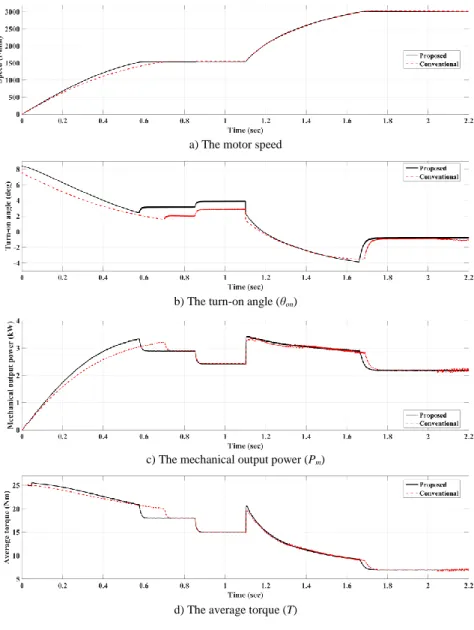
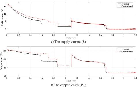
Figure 10 shows the simulation results under sudden-change of commanded speed and loading torque. The reference speed is suddenly changed from 1500 r/min to 3000 r/min at 1.1 sec. The motor started under load torque of 18 Nm. Then, the load torque is changed suddenly from 18 Nm to 15 Nm at 0.85 sec, and from 15 Nm to 7 Nm at 1.1 sec. Figure 10(a) shows the motor speed. As noted, the proposed control can achieve higher dynamic performance compared to conventional controller. It allows motor to reach its reference speed faster. The online variation of θon with motor speed and load torque/current is illustrated in
Figure 10(b). A fast and adaptive changing of θon is achieved as the proposed controller uses ANN to implement control algorithm. The mechanical output power and average torque are given in Figure 10(c) and Figure 10(d) respectively.
The proposed controller can provide higher average torque and mechanical output power over the entire speed range. Furthermore, it consumes lower supply current and dissipates lower copper losses as shown in Figure 10(e) and Figure 10(f) respectively.
a) The motor speed
b) The turn-on angle (θon)
c) The mechanical output power (Pm)
d) The average torque (T)
e) The supply current (Is)
f) The copper losses (Pcu) Figure 10
The simulation results with sudden change of reference speed and load torque
Figure 11(a, b) shows the torque/current and power/current ratios respectively.
The proposed control provides the highest ratios over the operating range of speeds. For high speeds (over 1500 r/min), the power/current ratio is constant as illustrated in Figure 11(b) after 1.1 sec. This means that all the current flowing in motor windings is an effective current that produces mechanical output power.
a) The torque/current ratio
b) The power/current ratio Figure 11
The torque/current and power/current ratios
Figure 12 shows the position of first-peak of phase current and peak phase current value. Under the analysis of static torque curves, the conventional controller gives optimum solution for θon by forcing the first-peak of phase current to occur at angle θm = 7.5° as shown in Figure 12(a). On the other hand, with the proposed controller, the position of first-peak of phase current does not have a constant value. It varies with motor speed and load torque especially at low speeds. As seen, it has a noticeable difference from θm = 7.5° for speeds lower than base speed (1500 r/min) and tends to be very close to θm = 7.5° for speeds higher than rated speed. Furthermore, the proposed controller allows phase current to always reach its reference level (16A) as shown in Figure 12(b).
The current waveforms at different speeds are shown in Figure 13. For both controllers, the position of first-peak of phase current is obvious to have a clear difference under low speeds of 1500 r/min, and have a small difference for higher speed of 3000 r/min. It can be noted that, for the proposed controller, the RMS phase current has a lower value compared to conventional controller especially at lower speeds.
The steady state torque-speed curve is shown in Figure 14. The proposed controller provides higher torque production with lower current consumption. It has approximately 4% improvement in torque production for speeds up to base speed (1500 r/min).
a) The position of first-peak of phase current
b) The peak value of phase current with proposed controller Figure 12
The simulation results under sudden change of speed and load torque
Figure 13
The phase current waveform at different speeds
Figure 14
The steady-state torque-speed curve
6 Experimental Verification
The controller performance is experimentally verified with four-phase 8/6 SRM.
The SRM specifications are given in the Table 1. The control algorithm is implemented using a Texas Instruments TMS320F28379D digital signal processor (DSP). The SRM is coupled to an electromagnetic brake (MAGTORL model 4605c), which acts as a mechanical load. The shaft torque is measured using a DRBK torque transducer. An incremental-encoder (600 PPR) is used to provide rotor position. The phase currents are measured using high-accuracy and linearity current transducers (LAH50-P). The voltage measurement is achieved using a high-speed and linearity op-amp based circuit. A three-phase transformer, three- phase diode rectifier, and capacitor are used to provide DC power. The data are collected and plotted using a data acquisition board (DAQ NI USB-6009) with LabView software. C2000 microcontroller support package and code composer studio (CCS) are used for DSP programming. The schematic diagram and the practical implementation of measurement platform are shown in Figure 15(a, b) respectively.
IGBT Bridge Converter
Encoder
IGBT Gate driver
DSP TMS320F28379D
Phase 2 Three
Phase Bridge Rectifier
+
-
DAQ-NI 6009 USB
DAC-B
Three Phase Transformer
Mains C
Phase 1
Rotor position, Speed
SRM
Torque Transducer Phase 4
Phase 3 Brake
DAC-A
Torque Phase voltage
Supply current
LabView MATLAB
CCS
}
Current & Voltage transduces Vdc
i1
i2
i3
i4
i1
i2
i3
i4
Te
V1 V2 V3 V4
a) The schematic diagram of measurement platform
SRM
Brake
3-ph Bridge IGBT Converter
DSP DAQ MATLAB
+ CCS
Gate driver Power Supply
Current Transducers
Encoder Encoder
interface Voltage
Transducers
Torque Transducer
b) The practical implementation of measurement platform Figure 15
The experimental test bench
Figure 16 and 17 show the waveforms of phase current and its phase position with the conventional and proposed controllers respectively. It is obvious that the conventional controller forces the first-peak of phase current to occur always at angle θm = 7.5° as shown in Figure 16(a, b) for low and high speeds respectively.
On the other hand, with the proposed controller, the first-peak of phase current occurs at different positions. This is clear in Figure 17(b) as the first-peak of phase current occurs at 12°. In addition, the current waveform has a very similar shape compared to obtained simulation results in Figure 13.
a) At speed of 335 r/min a) At speed of 251 r/min
b) At speed of 621 r/min b) At speed of 545 r/min Figure 16
The experimental waveforms of phase current and position with the conventional controller
Figure 17
The experimental waveforms of phase current and position with the proposed controller
Figure 18 and 19 show the waveforms of total electromagnetic torque, phases’
currents and supply current at low speed of 294 r/min and high speed of 806 r/min respectively. The applied supply voltage is 100 V. The inherited drawback of torque ripple for SRM is very clear especially at low speeds as shown in Figure 18(a). The average torque is calculated from the instantaneous torque signal. The motor phases are energized in a certain sequence as illustrated by phases’ currents in Figure 18(b). The supply current is given in Figure 18(c). A noticed part of this current is regenerated back to supply because of the chopping process. At higher speed, a single pulse control is employed and phase current becomes much smoother without chopping as shown in Figure 19(b). The supply current becomes almost positive without the negative regenerated part as illustrated in Figure 19(c).
a) The total electromagnetic torque a) The total electromagnetic torque
b) The waveform of phases’ currents b) The waveform of phases’ currents
c) The waveform of supply current c) The waveform of supply current Figure 18
The experimental results at speed of 294 r/min, 2.05 Nm, θon = 4°, θoff = 19°
Figure 19
The experimental results at speed of 806 r/min, 1.8 Nm, θon = 2°, θoff= 19°
Figure 20(a, b) shows the measured steady state torque-speed curve and torque/current ratio respectively. For the proposed controller, the average torque is improved very clearly especially at low speeds as shown in Figure 20(a). It has a good agreement with the simulation results obtained in Figure 14. The speed difference comes from different voltages as simulation is carried out with 400 V and practical measurements are taken with 100 V. For speeds lower than 600 r/min, the improvement of average torque production is about 5.3%. With the proposed control, the torque/current ratio is higher all over the speed range especially for lower speeds. As the speed increases the current control becomes very difficult, that is why the torque improvement is very clear for low speed than high speeds.
a) The experimental torque-speed curves b) The experimental torque/current ratio Figure 20
The experimental steady state results with Iref =5A
Conclusions
This paper presented an optimization based method for SRM control parameters to improve torque production. The proposed control calculates the most efficient θon
according to torque production and copper losses. Instead of the conventional analysis of static torque curves, a trust dynamic machine model is used to ensures the absolute calculation of optimum θon over the entire range of operating speeds.
This model is built using measured data of SRM magnetization characteristics.
The objective function is calculated within the Simulink model, using a two-
dimensional search algorithm. The obtained data are implemented using ANN.
The proposed controller offers low cost and simple implementation. It provides optimum motor operation over the entire speed range. It has a faster dynamic response. It can provide the highest torque/current and power/current ratios. It consumes lower supply current and dissipates lower copper losses. It does not depend on motor parameters and improves torque production capability by 5.3%
for speeds lower than the rated motor speed.
References
[1] Z. Yueying, Y. Chuantian, Y. Yuan, W. Weiyan, Z. Chengwen: Design and optimisation of an In-wheel switched reluctance motor for electric vehicles, IET Intelligent Transport Systems, 2019, Vol. 13, No. 1, pp. 175-182 [2] J. J. Wang: Parameter optimization and speed control of switched
reluctance motor based on evolutionary computation methods, Swarm and Evolutionary Computation, 2018, Vol. 39, pp. 86-98
[3] Y. Hu, W. Ding, T. Wang, S. Li, S. Yang, Z. Yin: Investigation on a multimode switched reluctance motor: design, optimization, electromagnetic analysis, and experiment, IEEE Transactions on Industrial Electronics, 2017, Vol. 64, No. 12
[4] Z. Zhang, S. Rao, X. Zhang: Performance prediction of switched reluctance motor using improved generalized regression neural networks for design optimization, CES Transactions On Electrical Machines and Systems, 2018, Vol. 2, No. 4, pp. 371-376
[5] J. Zhu , K. W. E. Cheng, X. Xue: Design and analysis of a new enhanced torque hybrid switched reluctance motor, IEEE Transactions on Energy Conversion, 2018, Vol. 33, No. 4, pp. 1965-1977
[6] H. Cheng, H. Chen, Z. Yang: Average torque control of switched reluctance machine drives for electric vehicles, IET Electrical Power Applications, 2015, Vol. 9, No. 7, pp. 459-468
[7] J. B. Bartolo, M. Degano, J. Espina, C. Gerada: Design and initial testing of a high-speed 45-kw switched reluctance drive for aerospace application, IEEE Transactions on Industrial Electronics, 2017, Vol. 64, No. 2, pp. 988- 997
[8] G. K. Ptakh, A. P. Temirev, D. A. Zvezdunov, A. A. Tsvetkov: Experience of developing and prospects of application of switched reluctance drives in Russian Navy Fleet, IEEE Conference and Expo Transportation Electrification Asia-Pacific (ITEC Asia-Pacific) 2014, pp. 1-4
[9] T. A. S. Barros, E. Ruppert: Direct power control for switched reluctance.
generator in wind energy, IEEE Latin America Transactions, 2015, Vol. 13, No. 1, pp. 123-128
[10] J. Kim, R. Krishnan: Novel two-switch-based switched reluctance motor drive for low-cost high-volume applications, IEEE Transactions on Industry Applications, 2009, Vol. 45, No. 4, pp. 1241-1248
[11] H. Chen, J. J. Gu: Switched reluctance motor drive with external rotor for fan in air conditioner,” IEEE/ASME Transactions on Mechatronics, 2013, Vol. 18, No. 5, pp. 1448-1458
[12] S. S. Ahmad, G. Narayanan: Linearized modeling of switched reluctance motor for closed-loop current control, IEEE Transactions on Industry Applications, 2016, Vol. 52, No. 4, pp. 3146-3158
[13] W. Uddin, Y. Sozer: Analytical modeling of mutually coupled switched reluctance machines under saturation based on design geometry, IEEE Transactions on Industry Applications, 2017, Vol. 53, No. 5, pp. 4431-4440 [14] C. Li, G. Wang, J. Liu, Y. Li, Yu. Fan: A Novel method for modeling the electromagnetic characteristics of switched reluctance motors, Applied Sciences, 2018, Vol. 8, No. 537, pp. 1-14
[15] D. S. Mihic, M. V. Terzic, S. N. Vukosavic: A New nonlinear analytical model of the SRM with included multiphase coupling, IEEE Transactions on Energy Conversion, 2017, Vol. 32, No. 4, pp. 1322-1334
[16] A. Argeseanu, E. Ritchie, K. Leban: Torque optimization algorithm for SRM drives using a robust predictive strategy, IEEE 12th International Conference on Optimization of Electrical and Electronic Equipment (OPTIM) 2010, pp. 252-257
[17] X. Wang, Z. Yang, T. Wang, D. He, Y. Huo, H. Cheng, G. Yu: Design of a wide speed range control strategy of switched reluctance motor for electric vehicles, IEEE International Conference on Information and Automation, 2015, pp. 294-299
[18] M. Hamouda, L. Számel: A new technique for optimum excitation of switched reluctance motor drives over a wide speed range, Turkish Journal of Electrical Engineering and Computer Sciences, 2018, Vol. 26, No. 5, pp.
2753-2767
[19] M. Hamouda, L. Számel: Optimum excitation angles for switched reluctance motor drives, XXXIII. Kando Conference, 2017, pp. 128-142 [20] S. R. Mousavi-Aghdam, M. R. Feyzi, N. Bianchi, M. Morandin: Design
and analysis of a novel high-torque stator-segmented SRM, IEEE Transactions on Industrial Electronics, 2016, Vol. 63, No. 3, pp. 1458-1466 [21] S. Nakano, K. Kiyota, A. Chiba: Design consideration of high torque- density switched reluctance motor for hybrid electrical vehicle, IEEE 19th International Conference on Electrical Machines and Systems (ICEMS) 2016
[22] H. Chen, W. Yan, J. J. Gu, M. Sun: Multiobjective optimization design of a switched reluctance motor for low-speed electric vehicles with a taguchi–
CSO algorithm, IEEE/ASME Transactions on Mechatronics, 2018, Vol. 23, No. 4, pp. 1762-1774
[23] B. Anvari, H. A. Toliyat, B. Fahimi: Simultaneous optimization of geometry and firing angles for in-wheel switched reluctance motor drive, IEEE Transactions on Transportation Electrification, 2018, Vol. 4, No. 1, pp. 322-329
[24] B. K. Bose, T. J. E. Miller, W. H. Bicknell, P. M. Szczesny, W. H.
Bicknell: Microcomputer Control of Switched Reluctance Motor, IEEE Transaction on Industrial Applications, 1986, Vol. IA-22, No. 4, pp. 708- 715
[25] C. Mademlis, I. Kioskeridis: Performance optimization in switched reluctance motor drives with online commutation angle control, IEEE Transactions on Energy Conversion, 2003, Vol. 18, No. 3, pp. 448-457 [26] Y. Sozer, D. A. Torrey, E. Mese: Automatic control of excitation
parameters for switched-reluctance motor drives,” IEEE Transactions on Power Electronics, 2003, Vol. 18, No. 2, pp. 594-603
[27] S. C. Wang, W. H. Lan: Turn-on angle searching strategy for optimized efficiency drive of switched reluctance motors, 30th Annual Conference of IEEE Industrial Electronics Society (IECON) 2004, Vol. 2, pp. 1873-1878 [28] Y. Z. Xu, R. Zhong, L. Chen, S. L. Lu: Analytical method to optimise turn-
on angle and turn-off angle for switched reluctance motor drives, IET Electric Power Applications, 2012, Vol. 6, No.9, pp. 593-603
[29] C. Lin, B. Fahimi: Optimization of commutation angles in SRM drives using FRM, IEEE Transportation Electrification Conference and Expo (ITEC) 2012, pp. 1-6
[30] H. Chen, X. Wang, X. Zan, X. Meng: Variable angle control for switched reluctance motor drive based on fuzzy logic, the fifth international conference on power electronics and drive systems (PEDS) 2003, Vol. 2, pp. 964-968
[31] H. M. Cheshmehbeigi, S. Yari, A. R. Yari, E. Afjei: Self-tuning approach to optimization of excitation angles for switched- reluctance motor drives using fuzzy adaptive controller, 13th European Conference on Power Electronics and Applications, 2009, pp. 1-10
[32] M. Hamouda, A. R. A. Amin, E. Gouda: A drive system design and implementation for switched reluctance motor based on wide range speed control, 17th International Middle East Power System Conference (MEPCON) 2015, pp. 1-8
[33] M. Hamouda, A. R. A. Amin, and E. Gouda: Artificial intelligence based torque ripple minimization of switched reluctance motor drives, 18th International Middle East Power System Conference (MEPCON) 2016, pp.
943-948
[34] S. Song, M. Zhang, L. Ge, “A new fast method for obtaining flux-linkage characteristics of SRM,” IEEE Transaction on Industrial Electronics, 2015, Vol. 62, No. 7, pp. 4105-4117
[35] R. Zhong, Y. Xu, Y. Cao, X. Guo, W. Hua, S. Xu, W. Sun: Accurate model of switched reluctance motor based on indirect measurement method and least square support vector machine, IET Electric Power Applications, 2016, Vol. 10, No. 9, pp. 916-922
[36] M. Hamouda, L. Számel: Accurate measurement and verification of static magnetization characteristics for switched reluctance motors, IEEE 19th International Middle East Power System Conference (MEPCON) 2017, pp.
993-998
[37] M. Hamouda, L. Számel: Torque control of switched reluctance motor drives for electric vehicles, Proceedings of the Automation and Applied Computer Science Workshop, 2017, pp. 9-20
[38] V. Oduguwa, A. Tiwari, R. Roy: Evolutionary computing in manufacturing industry: an overview of recent applications, Applied Soft Computing, 2005, Vol. 5, No. 3, pp. 281-299
[39] A. Ürmös, Z. Farkas, M. Farkas, T. Sándor, L. T. Kóczy, Á. Nemcsics:
Application of self-organizing maps for technological support of droplet epitaxy, Acta Polytechnica Hungarica, 2017, Vol. 14, No. 4, pp. 207-224 [40] R. E. Precup, S. Preitl, P. Korondi: Fuzzy controllers with maximum
sensitivity for servo systems, IEEE Transactions on Industrial Electronics, 2007, Vol. 54, No. 3, pp. 1298-1310
[41] M. Shams, E. Rashedi, S. M. Dashti, A. Hakimi: Ideal gas optimization algorithm, International Journal of Artificial Intelligence, 2017, Vol. 15, No. 2, pp. 116-130