A Novel Approach for Controlling the Electric Drives Used in Electric Trains
Mohamadali A. Vali, Jafar Monfared, Mehdi Amiri Dehcheshmeh and Hadi Givi
Department of Electrical Engineering, Amirkabir University of Technology (Tehran Polytechnic), Tehran, Iran
mohamadalivali@aut.ac.ir, monfared@aut.ac.ir, mehdi750@aut.ac.ir, hadi.givi@aut.ac.ir
Abstract: Nowadays, the DC motors have been replaced by induction motors in most of the industrial applications. Substantially, Induction motors are single speed, but they can produce high power density in a wide range of speed by applying new drive controllers based on constant V/f, DTC and vector control theory. Electric motors control is mainly accomplished by power electronic drives based on control schemes like constant v/f.
However, the challenge of torque generation with fast time response and high accuracy was met by using the controllers based on vector control and DTC. In applications like electric train, generation of torque with rapid time response is so vital. As an example, in Anti skid-Anti slid system, the generated torque should vary between zero and the desirable value quickly to prevent the electric train from slip and the wheels from skidding on the rail. However, the accuracy of the torque magnitude due to its high value is not an important issue and most of the time, errors up to 3 percents in the generated torque is acceptable.
In this paper, the control systems used in constant v/f drives are modified in order to generate torque with fast time response and acceptable accuracy. Control systems stability is an essential concern in electric drives and is arisen from the complexities in the controller’s process and the time delays. In the proposed system, by simplification of the drive controllers, the instability problem of the control units is eliminated which in turn reduces the calculation time delays and results in torque generation with appropriate time response. Furthermore, the overall cost of the drive system is reduced considerably.
Keywords: electric drive control; electric train; induction motor; Anti skid-Anti slid system
1 Introduction
Nowadays, railway transportation systems have received a great deal of attention.
Ease of displacement, capability of extensive transit of goods in a short time and environmentally friendly feature are all among the advantages that attracts the
attention of the governments and people to the electric trains. Nevertheless, the drive systems face to some limitations and challenges when they are applied to electric trains. For example, the motor torque must be generated according to the status of the wheel with respect to the rail so as to prepare the passengers comfort and to prevent the wheels from sliding on the rails in different situations like braking, primary accelerating and moving through slopes. In comparison to induction motors, DC motors were used in applications with a wide range of speed due to their simpler controllability. However, DC motors are bulk and massive and require various maintenance and services. On the other hand, their commutator and brush system is so sensitive and vulnerable. Furthermore, their manufacturing costs are considerable. Advances in power electronic and drive technologies led to the speed control of the induction motors in a wide range with high values of efficiency and power factor [11]. Although the first vector control based drive was installed in the Japan railway system in 1995 and became a conventional scheme, it faced to the problem of generating constant torque with high value while this problem is not concerned in the v/f drives [1]. As the effect of the stator voltage drop is ignored in v/f drives, complicated controllers are required to minimize the steady state speed error especially in low speeds and high values of load [2]. Using these controllers leads to the instability of the control system due to the time delays in the voltage drop compensation system. Therefore, PI controllers are required which in turn result in the severe dependency of the system to the machine parameters [3]. One of the problems in designing control systems for motors is the nonlinear relationship between speed and torque which is arisen from the dependency of these two quantities to the motor status including frequency and slip. In [4], using a new approximation of these two quantities, A.M-Garcia tries to improve the motor control but the requirement to calculation of the air gap power in his proposed linear expression increases the controller’s sensitivity which in turn leads to the error increase.
In this paper, a constant v/f based controller is designed using the linear relation between the torque and speed. This controller receives the reference values of the speed and torque and locates the drive at the desirable operating point with the shortest time response. Due to the elimination of differentiation and integration systems from the voltage compensator, the time delay problem in compensating voltage generation is solved which in turn leads to the drive overall stability. On the basis of the mentioned conditions, the v/f method for torque generation and speed control in an electric train is analyzed in this paper. Finally, the validity of the proposed method is verified by simulation of the drive system implemented on a 200 kVA induction motor [6, 7].
2 Speed Control by Changing the Voltage and Frequency
According to the following expression, the synchronous speed is directly related to the power supply frequency:
ms
p
4
(1)Thus, changing the supply frequency leads to the change in the motor synchronous speed. On the other hand, the induced voltage is proportional to the product of the frequency and the air gap flux. Therefore, if the frequency is reduced without any change in the supply voltage, the air gap flux will increase. Induction motors are designed to operate in the vicinity of the knee point of the magnetic saturation curve. Thus, the flux increase may result in the motor saturation. On the other hand, reduction of the motor flux is not desirable as it reduces the motor capacity.
Therefore, the frequency and the supply voltage are changed simultaneously to prepare the motor with a constant flux. Increasing the frequency to the levels more than the rated value is accomplished in a constant voltage. This is due to the stator insulation limitations. Suppose that the variable “a” is defined as:
rated
f
a f
(2)Where f and frated represent the operating and the rated frequencies respectively.
Obviously, for the operation in a constant flux, the magnetizing current “Im” should be kept in a certain constant value. Thus:
m rated rated m
rated
m
f L
E X
I E
2
1
(3) It is evident that for each new operating point, the new values of “E” and “f”should satisfy the above expression to ensure a new constant “Im”. Therefore, the machine flux remains constant.
In this paper, one approximation is utilized that is
V E
. This approximation is achieved by ignoring the voltage drop in the machine stator and obviously, it leads to desirable results in high speeds (high operating frequencies). In low speeds, this voltage drop can be compensated by adding this voltage to the machine input and considering the machine saturation effect. For the machine performance under and over the rated speed, the following expressions are presented where “ωms” represents the rated synchronous speed:rated
f
a f
(4.a)ms m ms
a s a
(4.b)
' 2 ' 2
' 2
3
r s r
r rated
ms
X X
as R
as V R
T
if a <1 (5.a)
' 2 2
' 2
' 2
3
r s s
r
r rated
ms
R a X X
s R
as V R
T
if a >1 (5.b)If the flux of the operating point is kept constant in a certain value by using a special strategy, a torque-speed characteristic like Figure 1 is achieved:
Figure 1
Torque-speed curve for the rated flux
But using the approximation
V E
, results in the characteristic presented in Figure 2.Figure 2
Torque-speed curve for “v/f = constant”
As seen in the above curves, in low operating frequencies (a<<1), the motor characteristic has a smaller break down torque. This characteristic can be improved by compensation of the stator voltage drop in the machine input and consideration of the machine saturation.
3 The State of the Voltage Source Inverter (VSI) Operation
The configuration of a 6-pulse inverter is illustrated in Figure 3:
Figure 3
Configuration of a 6-pulse inverter
Suppose that the switching control signals applied to the switches are in the form presented in table I:
Table 1
Switching control signals of the 6-pulse inverter Time (ɷt) Switches(ON) 0 < ɷt < π/3 1,5,6 π/3 < ɷt < 2π/3 1,2,6 2π/3 < ɷt < 3π/3 1,2,3 3π/3 < ɷt < 4π/3 2,3,4 4π/3 < ɷt < 5π/3 3,4,5 5π/3 < ɷt < 6π/3 6,4,5
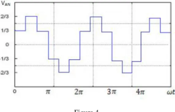
Using the switching signals presented in table I, the output voltage VAN will be in the form illustrated in Figure 4.
Figure 4 The inverter output voltage
It is obvious that the voltages VBN and VCN produced at the inverter output are the same as VAN but with the phase shifts equal to 120 and -120 degrees with respect to VAN respectively. Considering the Fourier series of the voltages VAB and VAN, the RMS value of the main harmonic and the RMS value of the phase voltage are presented below:
V
dV
2
1
(6.a)V
dV 3
2
(6.b)Therefore, the value of the sinusoidal voltage (main harmonic) applied to the motor is controlled by regulating the voltage Vd. The frequency of the inverter output voltage can be controlled by changing the switching intervals.
4 The State of Controlling the Drive Speed at the Speeds Lower and Higher than the Rated Speed
In drives utilized for electric train, the reference torque and speed are given to the drive and the goal is to control the drive in a way that it follows the reference torque and speed with an acceptable transient duration. To attain this purpose, two strategies can be chosen.
In the first strategy, the values of the reference torque and speed are given to the drive. The motor speed in sensed in each instant using a sensor and it is used for calculating the values of the slip and operating frequency in order to lead the motor to the desirable values of torque and speed. Obviously, this system is so accurate but deals with complexities in determination of the slip and operating frequency in each instant. On the other hand, since these values are attained using two nonlinear control systems, this process is time-consuming and may result in the instability of the system.
In the second strategy proposed in this paper, by considering the torque-speed characteristic obtained in the previous parts and using proper approximations, it is shown that using an estimator system for the operating frequency, the machine follows the values of the reference torque and speed with an acceptable accuracy in the steady state.
5 The State of Estimating the Machine Operating Frequency
By attaining the torque-speed characteristic of the machine in the rated frequency, it is deduced that in the frequencies lower than the rated value, the torque-speed characteristic has the same slope but it is just shifted with respect to the characteristic in rated frequency and is appeared with a new synchronous speed equal to aωms (ωms is the rated synchronous speed). In the speeds higher than the rated value, the characteristics slope is the same as the characteristic in the rated frequency but with a new break down (pull out) torque. This new break down torque can be determined by considering a constant power for the machine.
Different torque-speed characteristics can be obtained by changing the value of
"a". So a wide range of speeds and torques can be gained using these characteristics. By specifying the region of the reference torque and speed, namely by determining the operating frequency corresponded to the values of the reference torque and speed, the machine could be controlled in a way to follow the reference torque and speed in the steady state operation. In Figure 5, by regulating the reference torque and speed in a way to be located in the boundary area that has been shown in below figure, it is possible to control the motor so as to reach the desirable torque and speed with an excellent approximation in the steady state.
Figure 5
The operating region for following the reference torque and speed
It should be mentioned that by compensating the stator voltage drop in low operating frequencies, the drive operating region can be extended to the torques with values near the break down torque. Using the linear approximation, the torque – speed expression is attained for the speeds lower than the rated value in the following form:
max 0
T
ms ms
(7)6 Performance of the Drive under the Rated Speed
The slope of the other curves under the rated speed is assumed to be equal to (7).
Therefore, for the drive performance under the rated speed, the following expression is given:
mT a
ms
(8) This expression results in:ms
a mT
(9)In the above expression:
T T
ref and
ref. The value of "m" is attained using the torque-speed characteristic of the machine. So, by utilizing the values ofT
ref and
ref, "a" can be calculated using equation (2). As the drive is performing under the rated speed, the reference torque and speed are followed by using a voltage equal to "a" times of the rated voltage (V=a*Vrated).7 Performance of the Drive over the Rated Speed
At the speeds higher than the rated value,
T
maxis not constant and based on the operating speed,T
maxdecreases. Thus, the following expression can be considered as the linear approximation for this operating region:T
ms
T
ms ms
max 0
(10)As a result:
mT a
ms
ms
(11)The same as the operation under the rated speed,
T T
ref and
ref. "m"and "
ms" are gained from the normal operating characteristic of the machine.Therefore, "a" is calculated as:
ms ms
mT
a
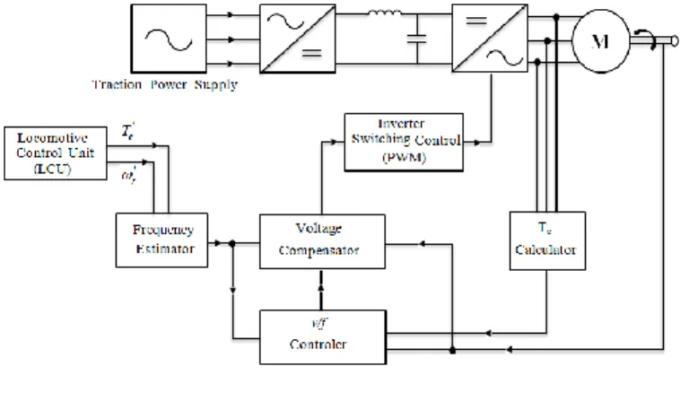
(12)Using this value of "a" and this time with the rated voltage, it is possible to follow the reference torque and speed. Drive system block diagram is shown in Figure 5:
Figure 6 Drive system block diagram
8 Drive System Simulation Results
The discussed drive is tested on a 200 kVA motor in order to evaluate the correct operation and calculations of the proposed method. It will be shown that the proposed drive can follow the reference torque and speed so accurately. The characteristics of the simulated motor are presented in table 2.
Table 2
Characteristics of the simulated motor
Quantity Value
Rated Power 160 kW
Rated Voltage 400 V
Rated Current 300 A
Frequency 50 Hz
Rated Torque 1000 N.m
Motor and its load inertia 5 kg.m^2
There is a comparison between two states, when the system operation is considered with voltage compensator and another state that the system operates without voltage compensator block. The nominal torque with consideration of the drive characteristic is 1000 N.m, and maximum torque is considered approximately three times more than nominal torque. Intrinsically, drive confronts with unsteady condition when operates at low speeds with high load torque, and by addition a new block named compensator block, the drive overcomes this situation and can produce high electromagnetic torque in low speed. The results of comparison between the states will be shown in the following:
A. T=3000 N.m;
=25rad / sec
Figure (7.a)
Drive speed and torque without voltage compensator
Figure(7.b)
Drive speed and torque with voltage compensator
B. T=2000 N.m;
=15rad / sec
Figure(8.a)
Drive speed and torque without voltage compensator
Figure(8.b)
Drive speed and torque with voltage compensator
C. T=1500 N.m;
=12rad / sec
Figure(9.a)
Drive speed and torque without voltage compensator
Figure(9.b)
Drive speed and torque with voltage compensator
D. T=1000 N.m;
=5rad / sec
Figure(10.a)
Drive speed and torque without voltage compensator
Figure(10.b)
Drive speed and torque with voltage compensator
As seen, in all mentioned conditions, when compensator block is not used, the motor is not able to follow the operating point (reference speed and torque). Then the drive system performance under practical conditions has been studied.
The simulation results are as following:
First, it is supposed that the motor is started and at t =1 sec, a torque is applied to the motor and this torque reaches to its rated value after 0.2 second and driver is going to produce this torque in the motor output and also put the train in a desirable speed (reference speed).
The simulation results for different values of the applied torque and the reference speed are presented below.
A. T=3500 N.m;
ref=140rad / sec
Figure (11.a) Drive system performance
B. T=4000 N.m;
ref=120rad / sec
Figure (11.b) Drive system performance
C. T=3000 N.m;
ref=110rad / sec
Figure (11.c) Drive system performance
D. T=2500 N.m;
ref=50rad / sec
Figure (11.d) Drive system performance
E. T=2000 N.m;
ref=20rad / sec
Figure (11.e) Drive system performance
F. T=3000 N.m;
ref=170rad / sec
Figure (11.f) Drive system performance
G. T=1700 N.m;
ref=200rad / sec
Figure (11.g) Drive system performance
H. Test with variations of the reference speed, analysis of accelerating, braking and the steady state in a route:
In this test, it is assumed that the motor is under a constant load with the value of 2000 N.m; Our purpose is to analyze the braking and accelerating states under this load torque. First it is supposed that the motor is rotating at a speed equal to 180 rad/sec which is higher than the rated value. Then the motor receives a command for decreasing its speed to 130 rad/sec and after becoming stable at this speed, again the motor receives a command for decreasing its speed to 90 rad/sec. So the motor adjusts itself to this new speed. After positioning at the steady state, a command for increasing the speed to 110 rad/sec is received and after passing the transient state, the motor adjusts itself to this command. The rotor speed and the torque diagrams for this test are represented below.
Figure (11.h) Drive system performance
The tests (A), (B) and (C) are performed under the speeds lower than the rated speed, while the tests (D) and (E) are done at low speeds and the tests (F) and (G) are performed at the speeds which are higher than the rated value.
The test (H) verifies the correct operation of the motor at the compound cycles and confirms the motor ability for braking, accelerating and reaching to the steady state with minimum error.
Conclusion
In the conventional v/f systems, the control system considers the slip and in each instant, solves the motor equations to follow the reference values of the torque and speed but in the method proposed in this paper, the normal torque – speed characteristic of the motor is utilized and by designing the Frequency Estimator unit, this purpose is attained simply and by a high stability. As confirmed in the tests, the proposed drive system can easily control the speed of the electric train in a wide range. As seen, this system is able to prepare the controller or the train driver with their desirable torque and speed simply. On the other hand, using the simplifications discussed above, this system can be easily implemented and manufactured, so the drive system manufacturing cost is reduced considerably.
Furthermore, as the control system for determination of slip and operating frequency is not utilized in the form of an instantaneous calculator, the system stability will increase and the control equipments for instantaneous calculation of the slip and operating frequency and also expensive sensors are not required anymore.
References
[1] M. Yano, M. Iwahori,‘‘Transition from Slip Frequency Control to Vector Control for Induction Motor Drives of Traction Applications in Japan,’’IEEE, 2003
[2] K. Koga, Y. Fukuoka,‘‘Constitution of v/f Control for Reducting the Steady State Speed Error to Zero in Induction Motor Drive System’’, IEEE, 1990 [3] A. Munoz-Garcia, T. A. Lipo, D. W. Novotny. “A New Induction Motor
V/f Control Method Capable of High-Performance Regulation at Low Speeds,” Industry Applications, IEEE Transactions on, Vol. 34(4), pp. 813- 821, July 1998
[4] A. M. Garcia, T. A. Lipo, D. W. Novotny,‘‘A New Induction Motor V/f Control Method Capableof High-Performance Regulation at Low Speeds’’
IEEE Trans Ind. Appl., Vol. 34, No. 4, July/August 1998
[5] P. L. Alger, Induction Machines, 2nd ed. New York: Gordon and Breach, 1970
[6] Jee-Hoon Jung, Gang-Youl Jeong, and Bong-Hwan Kwon, “Stability Improvement of V/f-controlled Induction Motor Drive Systems by a Dynamic Current Compensator,” Industrial Electronics, IEEE Transactions on, vol. 51(4), pp. 930-933, Aug. 2004
[7] K. Suzuki, S. Saito, T. Kudor, A. Tanaka, and Y. Andoh, “Stability Improvement of V/F Controlled Large Capacity Voltage-Source Inverter Fed Induction Motor,” Industry Applications Conference, 41st IAS Annual Meeting. Conference Record of IEEE, Vol. 1, pp. 90-95, Oct. 2006
[8] R. A. Hamilton and G. R. Lezan, “Thyristor Adjustable Frequency Power Supplies for Hot Strip Mill Run-Out Tables,” IEEE Trans. Ind. Gen.
Applicat., Vol. IGA-3, pp. 168-175, Mar./Apr. 1967
[9] F. Blaschke, ‘The Principle of Field Orientation as Applied to the New Transvector Closed-Loop Control System for Rotating-Field Machines,”
Siemens Rev., Vol. 34, pp. 217-220, 1972
[10] Zhiwen Ma, Trillion Zheng, and Fei Lin, “Stability Improvement of V/Hz Controlled PWM Inverter-fed Induction Motors Drives,” Industrial Electronics and Applications, 1st IEEE Conference on, pp. 1-4, Man 2006 [11] Cornell E. P., Lipo T. A., “Modelling and Design of Controlled Current
Induction Motor Drive Systems”, IEEE Trans Ind. Appl. 1977