THE A P P L I C A T I O N OF
S T R A I N G A U G E T E C H N I Q U E S TO THE M E A S U R E M E N T OF W E I G H T
P . A . J A S S O Y
Elliott Brothers (London) Limited, Lewisham, London, England
G E N E R A L
Definition
Weight, by definition, is the gravitational force acting upon a body of known mass. The measurement of weight, therefore, resolves itself into measurement of force (Fw = mG).
Measurement
This unknown force can be measured by opposing it with a known force—
generated by a given mass, a pressure, an electro-magnet or a spring [1].
Strain gauge technique
The technique to be described utilizes the properties of a spring to counter- balance the unknown force, and relies upon the law propounded by Robert Hooke (1635-1703) that the change in dimensions of a spring is, within the elastic limits of the spring material, proportional to the applied force. This change in dimensions is known as the "strain" in the spring, and can be measured by attaching a "strain gauge" to the spring. Weightmeasuring elements using these techniques are known as load cells.
A simple analysis is as follows:
s = e/E, (1) where s = strain; e = stress; and E = modulus of the material.
e = F/A, (2) where F = force applied; and A = cross-sectional area of strain element.
dr=Kds = Kd(FA)/(E), where r = strain gauge resistance; and K= gauge factor.
S T R A I N G A U G E S E.R.S. gauges
There are various types of strain gauges (i.e. resistive, acoustic, piezo
electric, etc.) but the most common is the electrical resistance strain gauge, commonly known as the E.R.S. gauge [4].
Construction
The E.R.S. gauge consists of thin backing material, such as paper, to which is cemented a grid of fine wire 0.025-0.050 mm in diameter. This wire has the property that its electrical resistance is directly proportional to its length and cross-sectional area (R = ρΙ/Α). If, then, the dimensions of the wire are changed i.e. it is strained, its resistance changes in proportion to the strain.
Printed circuit type
A n alternative method of E.R.S. gauge construction is to photo-etch a sheet of suitable conducting material which has an insulating backing material [2]. These " f o i l " strain gauges have the advantage that the strain wire is of comparatively large cross-sectional area and therefore is of high current carrying capacity. However, they are not considered by some manufacturers to be suitable for load cell transducers because of the lack of uniformity and stability.
Attachment
The strain gauge may be attached to the strain element along its whole length, in which case it is known as a bonded strain gauge, or may be attached at its ends, in which case it is known as an unbonded strain gauge.
A typical load cell using unbonded strain gauges is described by Laycock [3].
Required characteristics of strain gauges
Since high linearity between strain and resistance is comparatively easy to achieve with correct choice of the wire alloy, the main factor in determining the choice of strain gauge for use in a load cell is stability. This will depend on:
1. A low temperature coefficient of the wire used—the copper/nickel alloys being very suitable in this respect. Better temperature compensation can be partially achieved by using multiple gauge circuits and by matching the expansion coefficients of the strain wire and strain element materials.
2. The mechanical stability of the wire, which, to a great extent, is depen
dent on the manufacturing methods used. Uniformity of the materials employed and correct annealing after cold working are very important.
5. The mechanical stability and strength of the backing materials under load and temperature—the thermo-setting epoxy and phenol resins are satisfactory for this purpose up to approximately 200°C. A b o v e this tem
perature ceramic cements are superior and special techniques using "stripp- able" strain gauges are followed.
4. The strain sensitivity or gauge factor, i.e. the relation between change in resistance and change in strain should be constant. The copper/nickel alloys are suitable in this respect and the strain gauge factor is approxi
mately 2. Special types of semi-conductor material may have strain gauge factors as high as 120 but these materials are not stable enough for high accuracy measurement. It is, of course, very important that this factor should remain constant under normal changes of strain and temperature. Since this is not always the case special compensation measures may be necessary.
5. L o w cross-sensitivity, i.e. the sensitivity to strain along the axis at right angles with the major axis, should be as small as possible since this will ease the design of the strain element.
Choice of gauges
The choice of strain gauge will depend largely upon its dimensions in relation to the strain element—and this will determine its resistance, and current carrying capacity.
A typical value of resistance for a gauge grid of 5.0 χ 10.0 mm would be 100 Ω using constantan wire of 0.025 mm diameter. This resistance value results in a load cell of impedance suitable for use in conjunction with the instrumentation, as will be seen later.
S T R A I N E L E M E N T S General
These components are, as we have mentioned, specially designed springs.
They may be of ring, toroidal, columnar or cylindrical form, but are nearly always symmetrical about the force axis. In the columnar and cylindrical types, it is desirable that the height/diameter ratio should exceed 3:1 to ensure that the stress distribution in the strain gauge area is uniform. This criterion does, however, depend upon the manner in which the load is applied to the element.
Generally, the ring types are used for loads below 10,000 kg and the columnar types are used for loads above this capacity. There is no upper limit to the capacity of load cells, but the difficulty of heat treating columns of large cross-sectional areas resulted in the development of multi-column units.
2 - 60143045 I ώ Μ
In the very low weight ranges cantilever and diaphragm types of strain elements have been developed. The load limit of load cell capacity is reached when the strain element disappears completely and the strain gauge itself carries the load (accelerometers using this principle are in common use).
Construction
These elements may be fabricated from any material of suitable strength and elasticity—the most suitable being steel, beryllium copper or the alu- minium alloys. They should preferably be of "one piece" construction for the highest dimensional stability and may be forged, or machined from the solid.
Design
Generally the design cross-sectional area of the spring is chosen so that the strain does not exceed 0.2 per cent for maximum load. A n accurate knowledge of the strain in the strain element is unimportant since the load cell is always calibrated in a suitable testing machine. This approximate strain figure implies that the maximum stress in a steel member should be less than 45 kg/mm2 since the modulus of steel is approximately 2 2 x l 03 kg/mm2. In practice this stress is about 25 per cent of the proof stress of a hardened high tensile steel and the proportionality of strain to stress should be better than 0.05 per cent. It follows that the element will have a design safety factor of between 3 and 4 and the deflection (or change in length under load) will be 0.25 mm for an element having a length of 12.5 cm.
It is not possible to predict the success of any new design of load cell since the detailed stress analysis of complex shapes is not practical. One can lay down certain guiding principles, however, the most important being as follows:
1. The shape of the strained section should be as simple as possible.
Uniform stress distribution can be achieved by keeping the cross-sectional area constant.
2. The strain element should be of "one piece" construction.
3. The loading surface should be designed so that the force is applied along the axis of the strain member and is distributed over the strain area.
4. There should be no force applied to the strained member other than that due to the load. If this is unavoidable the extraneous force applied should be axial and a function of the force due to the load.
L O A D C E L L S General
Strain gauge weight transducers are commonly referred to as load cells.
They consist basically of one or more strain elements, each with two or more strain gauges bonded to it, in a suitable protecting case. The transducers may be designed to carry compression or tension loads.
Strain gauge circuit
The number of strain gauges used will depend upon the shape of the strain element and the necessity of integrating the strain, but normally there are at least four, connected in a Wheatstone bridge circuit, so that those gauges which are subject to a like strain are in opposite arms of the bridge.
Construction
It is clear that if the gauges are electrically identical, any temperature change which affects them all will not affect the bridge balance. It is, there- fore, very important that electrical and mechanical symmetry should be achieved, and that the strain gauge measuring element should have a large thermal capacity and be thermally shielded.
The strain element is always designed to measure the force along its major axis. It can be seen, therefore, that any other forces will produce undesired strains which will affect the measuring accuracy. In practice, the case is often designed with one or two inbuilt diaphragms. These diaphragms must be designed to carry the horizontal component of any non-axial load or side load, without affecting the sensitivity of the strain element materially.
Since the changes of resistance under strain are very small it is essential that the insulation resistance of the strain gauge network to ground should be very high. It follows that the bonding materials must maintain a high insulation resistance under varying temperature conditions and that the strain gauge circuit should be sealed inside the case so as to prevent ingress of water. It is easy to bring the incoming and outgoing connections through special seals and to provide a secondary protection for the strain element by covering it with a suitable waterproof material.
The load cell case is often designed with built-in passages for a cooling liquid so that, if necessary, the cell may operate under very high ambient temperature conditions.
Calibration
A s has been stated, the load cells are individually calibrated by applying a known load and adjusting dropping resistors in the excitation circuit so that the output is a standard figure. Normally, a complementary range of
load cells will be designed to cover known requirements and for a particular application a number of cells will be used to support the load. It is desirable, therefore, that each type of load cell in the range is calibrated to give a standard electrical output for its rated load. Load cells and measuring instruments are then interchangeable.
Bonding materials
The cements used for attaching the strain gauges to the strain element must be capable of faithfully transmitting the strain, which implies that it must have good adhesive properties, strength and elasticity. The thermo setting epoxy and phenol resins, as has been stated, are suitable for use up to temperatures of 200°C. The curing temperatures are somewhat higher than this and the cure is continued until the insulation resistance of the adhesive reaches the maximum—generally after 18-24 hours (it should be remembered that the gauges should be applied under pressure to a suitably etched surface and under scrupulously clean conditions). The bonding pressures for the phenol resins are somewhat higher than those for the epoxy
resins.
Electrical output
The electrical output is, as has been stated, directly related to the strain.
In a columnar type of strain element designed for a strain of 0.2 per cent at full load, the output for a 4-gauge bridge circuit with two axial gauges and two gauges at right angles to the axis will be approximately 0.26 per cent of the input voltage, i.e. 2.6 mV per volt. (See Appendix.) The maximum input voltage depends upon the current which the strain gauge can carry without raising its temperature significantly, and will (for a wire gauge) be of the order of 30-40 m A . For 100 Ω gauges in the 4-gauge configuration the maximum excitation voltage is, therefore, 8 V. The output voltage will then be 16 m V for full load.
Compensation
1. Partial zero temperature compensation can be achieved by methods previously discussed. In addition, it is necessary for the highest accuracy to compensate further by matching the temperature coefficients of the gauges and connecting a temperature sensitive resistance in the strain gauge circuit so that asymmetrical changes in strain gauge resistance due to tem
perature, are cancelled by an equal and opposite resistance change of the compensating resistance. A short section of copper or platinum wire is often used for this component.
2. T o compensate for change in the modulus of the strain materials and the strain sensitivity of the strain wire with temperature, it may be necessary
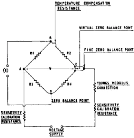
TEMPERATURE COMPENSATION I RESISTANCE"
Fig. 1.—Load cell calibration circuit diagram.
to connect a further temperature-sensitive resistor in the supply circuit to the strain gauge bridge (Fig. 1).
3. The compensating components mentioned above will have to have their characteristics determined experimentally. On the basis of a number of tests, average values are determined for each particular type of cell.
4. Typical temperature coefficients of zero and modulus for a highly compensated load cell will be 0.005 per cent/°F and 0.0005 per cent/°F.
Fig. 2.—Simplified measuring circuit.
L O A D C E L L S Y S T E M S
1. The measuring system consists of one or more load cells and a suitable measuring instrument.
2. The load will normally be distributed over three or four load cells and the outputs of the cells will be integrated by connecting them either in series or parallel. The series connection gives a more accurate summation, but has the disadvantage that each load cell must have a separate supply, thus increasing the system complexity.
3. The measuring instruments used for high accuracy load cell weighing aie invariably of the self-balancing potentiometric type (Fig. 2). This system is self-compensating for power supply variations, as the power unit supplies both the load cell and the measuring circuits. For simplicity and accuracy the A . C measuring system is almost always used and the power supply unit is, in fact, a specially designed multi-wound mains transformer.
The only disadvantage of this system is that it is sensitive to interference at the supply frequency and it is necessary to screen all signal leads and balance cable capacities. The problem of interference becomes more critical as the signal circuit impedance is increased, and it is, therefore, considered desirable to keep the strain gauge circuit resistance at about 100 ohms, as previously mentioned. Where heavy electrical interference is experienced higher supply frequencies may be used, e.g. 400 c/s, or the D.C. system can be utilized.
Self-balancing potentiometric instruments have response times of one second or better, which is adequate for all normal weighing operations.
With suitable design the full scale accuracy of these instruments can be better than 0.1 per cent and since the signal input for full scale may be as small as 4 mV, it is possible to use scale expansion to achieve overall ac
curacies of 0.05 per cent of full load—and even higher sensitivities [5].
4. With possible measuring accuracies of the above order, careful instal
lation becomes extremely important. Continuity and high insulation resi
stance in the signal circuits must be beyond question. It becomes necessary, therefore, to have very stable mechanical connections and to ensure that all cables and connecting boxes are protected and waterproof. If the normal change in resistance for full scale is 0.2 per cent, and the measuring accuracy must be 0.05 per cent, the measuring circuits must have a resistive stability of one part in 106! In a signal circuit of 400 Ω impedance this is represented by a shunt resistance of 400 Μ Ω !
5. It is often required to indicate or record the weight digitally, especially when computations have to be performed. This can be achieved by either (a) Fitting a mechanical or optical encoder to the dial pointer shaft, or (b)
Using an electronic analogue digital encoder such as a digital valve voltmeter to measure the amplified output of the load cell.
The former system is inherently capable of higher accuracy and sensi- tivity, but, the latter has the advantage of a faster response time.
Once the weight information is in digital form it can readily be printed or punched on to tape or cards, which can then be processed together with other data to give rate of flow, totals and sub-totals, cost, or other information of interest to management. Many systems of this kind have
been tailor-made for recording material distribution.
A P P L I C A T I O N S General
Because of their small size, high speed of response, robustness, reliability and flexibility of installation, load cells can be used to solve a wide variety of weighing problems more successfully than mechanical weighing machines.
The major applications are treated separately but they can generally be divided into two classes—static and dynamic weighing. That is, weighing static material or moving material.
Mechanical considerations
The essential requirement of all weighing machines is that they should measure the gravitational force only. Extraneous forces caused by friction, wind loading, vibration, temperature changes, etc., must be minimized.
General rules for the installation of load cells are as follows:
1. The load cell should be mounted with its axis vertical, on a firm base.
2. Connections to the load, e.g. pipes, should be flexible in the vertical plane.
3. There should be suitable clearances round the load and its supporting structure, to prevent the possibility of frictional losses.
4. If the load is subject to side forces, (e.g. wind forces) it should be
"stayed" by suitable horizontal tie rods.
5. If the load is subject to thermal or elastic movements which cannot be restrained, special mounting arrangements must be incorporated which allow it to move relative to the load cell.
6. Shock loads, that is, instantaneous forces due to decelerations of the load, must be minimized. It is possible for the decelerations to exceed 100 G, and, in such a case, the load cell would be damaged. It is usual, therefore, to have a suitable overload protection device, such as a spring shock mounting, under these conditions.
T Y P E S O F W E I G H I N G M A C H I N E S Hopper and tank weighing
The small size of load cells allows them to be easily incorporated into the supporting structures of hoppers and tanks. Furthermore, since the meas- uring instruments can be remote, a manual or automatic switching system allows the contents to be monitored on one instrument. Automatic scaling can also be incorporated for containers of different capacity.
Crane weighers
Load cell weighing on cranes can be achieved either by incorporating the cell into the crane hook or by measuring rope tension. The second method has the disadvantage that bearing and rope friction cannot be avoided, but allows the cell to be placed in a safer position. In practice the friction errors can be made very small. The indication, of course, can be remote, and is usually in the crane driver's cab.
Belt weighers
In this application a short section of the conveyor belt is supported by load cells. The high speed of response of the load cell system gives inherently higher accuracy, and the simplicity and reliability of the system, which con- tains no moving parts and is sealed, is very attractive. Correction for changes in belt speed can be made simply by exciting the load cell from a voltage generator driven from the belt.
Constant weight feeders
Similar principles of operation to those in the belt weigher are utilized.
The weight of material on a sample length of belt is measured and the resulting signal controls the position of the outlet gate of the hopper feeding the belt, so as to keep the sample weight constant. The flow rate equals the weight per unit length multiplied by the belt speed. If, therefore, these two variables are kept constant, the flow is constant. A n alternative method is to vary the belt speed inversely with respect to the sample weight. Thus, if this weight increases, the belt speed is reduced proportionally. A n y number of these feeders can be used in parallel for continuous proportioning, or, alternatively, the flow rate of one material can be controlled proportionately to the measured flow rate of another ingredient.
Weighbridges
Load cell weighbridges have the advantage that their performance remains consistent under arduous operating conditions. Little or no maintenance
A P P E N D I X
Referring to Fig. 1 strain gauges Rl and R4 are positioned parallel to the axis of a columnar load cell and are therefore subject to a compression strain under load. R2 and R3 are on a diameter normal to the axis and are at right angles to R\ and R4. They are, therefore, subject to a tension strain under load.
If V is the input voltage and dR^-dR^ is the change of resistance in strain gauges R^R^.
R1 + R2 + dR1 + dR2 v ' V(R3 + dR3)
and vAD = - „ 3 J n 3\n . (2)
R3 + RA + dR3 + dRt v ' N o w if
R1 = R2 = R3 = Rt = R and dR1 = dR± and dR2 = dR3, V(dR1-dR3)
t h 6 n v B D = 2R + dR1 +
jRr
K (3)N o w
f - f - * .
where Κ is the gauge factor, and s is the axial strain
is required and the indication can be at any distance from the platform.
The civil work of preparing the excavation and foundations is very much cheaper, owing to the low height of this type of weight platform.
Force measurement
Load cells are widely used for measuring the force in rolling mills, dies, dynamometers and torque meters. The methods used are similar to those in weighing applications.
S U M M A R Y
Mechanical weighing machines have three major disadvantages, viz., the comparatively slow response due to the inertia of the moving parts, deterio
ration in accuracy due to wear, and, for the higher capacity machines, size and bulk. Furthermore, they do not readily lend themselves to remote indication or recording and are comparatively difficult to install.
Strain gauge weight transducers overcome all of these faults and can be manufactured to give the same order of weighing accuracy.
R E F E R E N C E S 1. JASSOY, P. Α., Brit. Comm. and Elect. 348 (1960).
2. JACKSON, P., Instrument Practice, p. 775, 1953.
3. LAYCOCK, G. H . , SOC. Inst. Technology.
4. MURRAY, W . M . and STEIN, P. K., Strain Gauge Techniques M.I.T., (1958).
5. SIMMS, R. B., Control (1960).
dR2 dR3
and
V
=V
= _^ '
where ρ = Poissons ratio.
Substituting equations (1), (2) on page 15 in equation (3), VKF(l+p)
h 2AE '