INTERNATIONAL SCIENTIFIC CONFERENCE ON ADVANCES IN MECHANICAL ENGINEERING 10-11 October 2019, Debrecen, Hungary ____________________________________________________________________
_______________________________________________________________________________________
1
DESIGNING AND ANALYSIS OF SPECIAL GEAR PAIRS BY GEARTEQ AND SOLIDWORKS SOFTWARES
BODZÁS, Sándor, Ph.D.
University of Debrecen, Department of Mechanical Engineering E-mail: bodzassandor@eng.unideb.hu
Keywords: GearTeq, Solidworks, software, gear, CAD
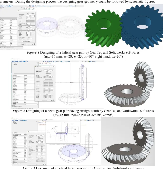
The GearTeq software is a unique designing program for many types of gear pairs (spur gears, helical gears, bevel gears, worm gears, elliptical gears, epicyclic gear trains, etc.). Knowing of the recommendation of the references an engineer can set the input parameters of several pinion and driven gears and after that this program can calculate the other necessary parameters. During the designing process the designing gear geometry could be followed by schematic figures.
Figure 1 Designing of a helical gear pair by GearTeq and Solidworks softwares (max=15 mm, z1=20, z2=25, β0=30°, right hand,α0=20°)
Figure 2 Designing of a bevel gear pair having straight tooth by GearTeq and Solidworks softwares (max=5 mm, z1=20, z2=30, α0=20°, Σ=90°)
Figure 3 Designing of a helical bevel gear pair by GearTeq and Solidworks softwares (max=5 mm, z1=20, z2=30, α0=20°, Σ=90°, right hand, β0=20°)
INTERNATIONAL SCIENTIFIC CONFERENCE ON ADVANCES IN MECHANICAL ENGINEERING 10-11 October 2019, Debrecen, Hungary ____________________________________________________________________
_______________________________________________________________________________________
2
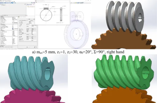
If we know the geometry of the pinion or the cutting tool this software can determine the connecting element by the kinematic track of the tool or double wrapping. Unique gear geometries could be designed by overwriting of the references. All of the determined parameters could be saved into Excel and the geometric shapes could be saved into SolidWorks designer software for further utilization (motion simulations, CAM, CNC designing, TCA, etc.). In this topic some our-designed special gear pairs are shown.
a) max=5 mm, z1=1, z2=30, α0=20°, Σ=90°, right hand
b) max=5 mm, z1=4, z2=30, α0=20°, Σ=90°, right hand c) max=5 mm, z1=6, z2=30, α0=20°, Σ=90°, right hand Figure 4 Designing of cylindrical worm gear drive by GearTeq and Solidworks softwares
Figure 5 Designing of epicyclic gear train by GearTeq and Solidworks softwares (max=5 mm, zinternalg=67, zsungear=37, zplanetp=15, α0=20°)
Figure 6 Designing of internal gearing by GearTeq and Solidworks softwares (max=5 mm, z1=20, z2=10, α0=20°)
Acknowledgments. This research was supported by the János Bolyai Research Scholarship of the Hungarian Academy of Sciences.