Journal of Physics: Conference Series
PAPER • OPEN ACCESS
Analytical and FE calculations for determining the nominal tooth root stress for external, cylindrical gears with symmetric and asymmetric profile
To cite this article: D Debreczeni and G Bognár 2020 J. Phys.: Conf. Ser. 1564 012020
View the article online for updates and enhancements.
This content was downloaded from IP address 80.98.174.11 on 04/07/2020 at 14:48
MMCTSE 2020
Journal of Physics: Conference Series 1564 (2020) 012020
IOP Publishing doi:10.1088/1742-6596/1564/1/012020
Analytical and FE calculations for determining the nominal tooth root stress for external, cylindrical gears with symmetric and asymmetric profile
D Debreczeni1 and G Bognár1
1 University of Miskolc, Institute of Machine and Product Design, Miskolc- Egyetemváros H-3515 Hungary
E-mail: v.bognar.gabriella@uni-miskolc.hu
Abstract. The present work deals with the geometry dependence of the nominal tooth root stress of external toothed, cylindrical gears. The profile geometries required to perform the calculations are derived by our own program in MATLAB. Finite element simulations are executed in Abaqus. When designing the models, the geometric constraints of each tooth crown were optimized, keeping in mind the accuracy of the simulation. In addition to the analysis of the significant tooth stress value of symmetrical element pairs, special emphasis is placed on the development of the position of the critical cross-section. The numerical results obtained are also compared with the most significant standardized methods used in practice.
The effect of the asymmetric design of the tooth profile on the nominal tooth root stress is reviewed in our investigations. The purpose of the numerical simulations carried out here is to determine the effect of the coast side angle on the dominant tooth root stress. In the evaluation of the results, the location of the critical cross-section, in addition to the magnitude of the stress, is also considered.
1. Introduction
The modern demand for power drive elements is the continuous increase in torque transmitted at the same dimensions. This objective makes it increasingly important for development engineers to make accurate estimates of the load capacity of gears. This ensures the required probability of serial production failure. As a result, many studies are focused on mapping and extending the boundaries of standardized European [1] and American [2], [3] procedures, for example Li [4] 's work on the effect of addendum factor and Zhan' s [5] work on numerical computation of the results of AGMA [2], [3].
In the study by Döbereiner [6] it was shown that the calculation procedure of the European calculation method usually leads to oversizing of the load capacity in case of high and sometimes helical teeth.
The significance of the change of load direction is demonstrated in Brinck's dissertation [7]. The effect of centrifugal force on the tooth root capacity of high-speed, narrow-rimmed, webbed gears has been investigated by Li [8]. An example of a mathematical model based on the ISO [1] standard for a more accurate determination of the tooth root stress has been found by Sánchez et al. [9]. The solutions developed by the authors is based on the load distribution model described by Pedrero et al. [10].
Increasing demand on tooth load capacity have resulted the appearance of asymmetric profiles in several areas. The analysis of these pair of gears and their integration into standardized methods have been addressed, among others, by Langheinrich [11] and Cavdar et al. [12] [13]. Numerical
MMCTSE 2020
Journal of Physics: Conference Series 1564 (2020) 012020
IOP Publishing doi:10.1088/1742-6596/1564/1/012020
2
examination of the significance of asymmetric profiles is found in the work of Pedersen [14] and Prabhu Sekar and Muthuveerappan [15], while the experimental analysis is found in Demet and Ersoyoǧlu [16]. Examination of the effect of asymmetric design on the bending strength can also be found in the work of Kapelevich [17] and Senthil Kumar et al. [18], where the authors emphasized the determination of the optimum profile shift coefficient for the tension.
In determining the load capacity, the effect of increasing the tension due to too narrow a rim thickness, which is considered by a separate factor of the ISO standard, can in many cases occur. The importance of the rim thickness chosen has also been addressed in recent studies such as Mallesh et al.
[19].
The standardized calculation methods imply a number of theoretical approaches. For example the negligation of certain stress components or the definition of dangerous cross-section. This work analyzes these theoretical approaches according to finite element calculations. First, the most important questions of precise finite element modeling of cylindrical gears for tooth root stress calculation are presented. The numerical results of symmetrical element pairs are compared with the results and definitions of European [1] and American [2], [3] standards. After symmetric profiles, the effect of asymmetry in the profile on the value and position of maximum tooth root stress is presented based on numerical calculations.
In this work the correlation of the different methods for the calculation of nominal tooth root stress is presented. The obtained results give base information for the discretion of the significance of a notch in tooth root geometry and draw attention to the potential of use of asymmetrical design.
2. The setting of FE models
The numerical calculations performed refer to the plane deformation state in accordance with the most significant analytical methods in practice. Thus, only plane models are used in the investigations. This approach allows mapping the behavior of applied geometry using finite element analysis with minimal computational capacity and direct correlation analysis by analytical methods. The modeling of the gear wheels on the Pfauter machining site is done by Litvin [20] using a proprietary program.
Elemental contact is defined as Hertz's frictionless contact. The contact gears were treated as separate elements throughout the calculation.
In the current simulations, a quadratic quadrilateral mesh has been used with the greatest possible stability of the results. The element size required in the tooth root was determined by preliminary calculations depending on the module used. In the current models, the average distance between adjacent nodes on the examined tooth curve is 0.05% of the tooth height.
When defining a tooth tension image, by examining a geometrically well-defined area of a given tooth, it seems obvious to greatly reduce the extent of the imported geometry. There are basically two ways to do this, namely by specifying the number of teeth considered and specifying the thickness of the rims.
The definition of the number of teeth per element in the simulation, according to Langheinrich [11], should preferably be set to 5. In all cases, the tooth under examination is located in the center, which in this case represents 2-2 additional teeth on each side. Langheinrich evaluated the accuracy of the simulation for the calculation of the tooth stress using equation (1). Here Nz represents the number of teeth considered in the simulation while Nzmax represents the actual number of teeth on the gear.
The loaded tooth is always centered on the two sides by the same number of unloaded adjacent tooth.
The sum of these determines the value of Nz.
(1)
Langheinrich's results in this regard are illustrated in figure 1. It can be seen that "further increasing the number of teeth taken into consideration by 5 does not result in a significant change in the amount of tooth tension."
MMCTSE 2020
Journal of Physics: Conference Series 1564 (2020) 012020
IOP Publishing doi:10.1088/1742-6596/1564/1/012020
Figure 1. Numerical tooth stress dependence of tooth number. [11]
According to the ISO [1] standard, the rim thickness factor should be chosen to be approximately 3 times the normal module thickness. To completely exclude the effects of the wheel hub being too narrow, the models used have a crown thickness of 4 times the module.
Figure 2. Structure of FE models.
The models with the geometric constraints shown in figure 2 were also compared to full-scale cases by selecting random sample pairs. Comparisons have confirmed that the effect of the chosen geometric boundaries on results is negligible.
3. Correlation of the results of symmetric element pairs
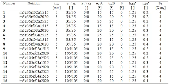
The evolution of the tooth tension of symmetrical teeth is presented by correlating the results of FEM, ISO [1] and AGMA [2], [3]. The gear types used in the relevant investigations are summarized in table 1. Related pairs are always identical. The perimeter line pressure is 300N. Tooth markings with code number m5z35rf02a2020 can be interpreted as follows:
- normal module: 5mm - number of teeth: 35 - profile shift factor: 0
MMCTSE 2020
Journal of Physics: Conference Series 1564 (2020) 012020
IOP Publishing doi:10.1088/1742-6596/1564/1/012020
4
- angle, drive side (side A): 20°
- profile angle, coast side (side B): 20°
- helix angle: 0 ° - dedendum factor: 1,25
- root radius factor of the reference profile: 0.2 - rim thickness: 4 * normal module
Table 1. Symmetric pairs of elements
It is important to emphasize that even the European standard only considers bending stress, whereas the AGMA standard considers the compressive stress of the tooth root in the calculation.
Based on these, it is expected that the AGMA standard will typically have lower tension values, since the consideration of the compressive load considered to be the relevant drawn pull is beneficial.
However, we should not forget that there are several differences in the theoretical approach of the two methods. These differences can sometimes disrupt the tendency. However, the theoretical importance of taking stress into account is clearly enhanced by increasing the profile angle. As a result, a significant profile angle dependence can be predicted for the AGMA standard nominal stress calculation compared to the ISO calculation, which is reflected in the results of figure 3.
Figure 3. Tooth root stress for symmetric element.
MMCTSE 2020
Journal of Physics: Conference Series 1564 (2020) 012020
IOP Publishing doi:10.1088/1742-6596/1564/1/012020
However, the finite element models show a difference in the position of the dangerous cross section compared to the standardized solutions. Therefore, it is worth examining the evolution of numerical stress values in the ISO standard cross section. These results are also shown in figure 3. However, the discrepancies shown here in relation to the European direction no longer show a clearly more favorable correlation.
It is important that different standardized methods use different permissible tensions to determine load capacity. As a result, the nominal stresses under the various procedures do not necessarily reflect the ratio of safety factors.
Figure 4. Dangerous cross-section of symmetric pairs.
When describing the position of a critical point, it is worth choosing the ISO standard as a benchmark. The European calculation uses a fixed dangerous cross-section. The American method, on the other hand, makes the dangerous cross-section dependent on the contact position. Numerical calculations also show a point-to-point shift at the critical point position. Of course, it is still worth assigning the dangerous cross-section to the critical point at the outer position of the single-tooth pair contact phase (point B).
The angular values δ of the tangents of the dangerous cross-sections to the centerline in the position of tooth top (point A) and in the point B connections are shown in figure 4. According to the US standard, the tangent in point B is between 26.6° and 33.2°, and in point A is 13.7° and 17.9°. The oscillation of the position of the numerical stress is much more significant, which in the case of the tested variants can be in the range of 38.0- 50.1° in point B and in the range of 27.3° - 45.2° in point A.
4. Effect of asymmetry
In this section, the influence of different drive and coast side profile angle on numerical results is presented. The tests are also evaluated based on the magnitude and position of the first main stress in the cage. Asymmetric variants used in the calculations are denoted in accordance with the symmetric variants summarized in table 1.
When evaluating the effect of the coast side profile angle, it is worth expressing the profile angle of the coast side as a function of the drive side. As a result, profiles are obtained which can be used to present the effect of the changes in each characteristic in a clear format. Accordingly, figure 5 summarizes the dependence of the tooth root stress on the coast side profile angle of the models with 0.2 root radius factor. The abscissa of the charts shows the increment of the cost side profile angle relative to the drive side. Thus, the position 0 denotes the symmetric element pair. It can be seen that
MMCTSE 2020
Journal of Physics: Conference Series 1564 (2020) 012020
IOP Publishing doi:10.1088/1742-6596/1564/1/012020
6
increasing the tooth root radius of the reference profile slightly mitigates the effect of the change of the coast profile angle on the active side. However, this does not result in a difference of more than 0.1% / ° in current experiments.
Figure 5. Tensile stress of asymmetric battery pairs.
Figure 6. Tension on asymmetric battery pairs with different foot heights
In the cases studied so far, each variant had a dedendum factor of 1.25. This parameter of the tooth profile is decisive for the influence of the examined asymmetry on the dominant tooth tension.
Accordingly, figure 6 shows the results of two sets of gears which differ only in their dedendum factor. The 1.35 variants show a slightly less than 1.1-fold trend compared to the standard 1.25 foot height models.
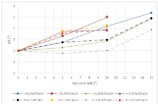
The effect of the asymmetrical construction of the tooth profile on the position of the dangerous cross-section is shown in figure 7. The position of the critical point is evaluated as a function of the angular change of the Δδ tangents to the centerline of the profiles. Studies show that the increase of the coast profile angle results in a slight migration of the drive sided critical point towards the foot, but this change is negligible for practice.
MMCTSE 2020
Journal of Physics: Conference Series 1564 (2020) 012020
IOP Publishing doi:10.1088/1742-6596/1564/1/012020
Figure 7. Dangerous cross-section of asymmetric element pairs.
5. Conclusions
The tests carried out have shown that for the symmetrical variants tested, the numerically significant maximum tooth stress value correlates well with the ISO standard value. In contrast, the location of the critical cross-section differs from the standardized procedure. The numerical calculations show the shift of the critical point towards the gear body.
Examination of the effect of asymmetry has highlighted the importance of the coast side profile angle of the tooth profile on the drive side first prime stress, which increases with the increase of the dedendum factor. The simulations performed proved that the determination of the dangerous cross- section of the asymmetric profiles can be considered independent of the coast side angle.
Consequently, the position of the drive sided dangerous point of the asymmetric variants can be the same as the symmetric element pair corresponding to the active side profile angle.
Acknowledgement
This work was supported by project no. 129257 implemented with the support provided from the National Research, Development and Innovation Fund of Hungary, financed under the K 18 funding scheme. The described study was carried out as part of the EFOP-3.6.1- 16-00011 “Younger and Renewing University – Innovative Knowledge City – institutional development of the University of Miskolc aiming at intelligent specialization” project implemented in the framework of the Szechenyi 2020 program. The realization of this project is supported by the European Union, co-financed by the European Social Fund.
References
[1] ISO 6336-3 2007 Calculation of load capacity of spur and helical gears - Part 3: Calculation of tooth bending strength International Organization for Standardization (Geneva)
[2] AGMA 2001-D04 2004 Fundamental Rating Factors and Calculation Methods for Involute Spur and Helical Gear Teeth American Gear Manufacturers Association (Alexandria) [3] AGMA 908 1989 Geometry Factors for Determining the Pitting Resistance and Bending
Strength of Spur, Helical and Herringbone Gear Teeth American Gear Manufacturers Association (Alexandria)
MMCTSE 2020
Journal of Physics: Conference Series 1564 (2020) 012020
IOP Publishing doi:10.1088/1742-6596/1564/1/012020
8
[4] Li S 2008 Effect of addendum on contact strength, bending strength and basic performance parameters of a pair of spur gears Mech. Mach. Theory 43 p 1557-84 doi.org/10.1016/j.mechmachtheory.2007.12.010.
[5] Zhan J, Fard M and Jazar R 2015 A quasi-static FEM for estimating gear load capacity Measurement 75 p 40-9 doi.org/10.1016/j.measurement.2015.07.036.
[6] Döbereiner R 1998 Tragfähigkeit von Hochverzahnungen geringer Schwingungsanregung Diss.
Technical University of Munich (Munich)
[7] Brinck P 1989 Zahnfusstragfähigkeit oberflächengehärteter Stirnräder bei Lastrichtungsumkehr Diss. Technical University of Munich (Munich)
[8] Li S 2012 Effects of centrifugal load on tooth contact stresses and bending stresses of thin- rimmed spur gears with inclined webs Mech. Mach. Theory 59 p 34-47 doi.org/10.1016/j.mechmachtheory.2012.08.011.
[9] Sánchez M B, Pedrero J I and Pleguezuelos M 2013 Critical stress and load conditions for bending calculations of involute spur and helical gears International Journal of Fatigue 48 p 28-38 doi.org/10.1016/j.ijfatigue.2012.11.015.
[10] Pedrero J I, Pleguezuelos M and Muñoz M 2011 Critical stress and load conditions for pitting calculations of spur and helical gear teeth Mech. Mach. Theory 46 p 425-37 doi.org/10.1016/j.mechmachtheory.2010.12.001.
[11] Langheinrich A 2014 Geometrie, Beanspruchung und Verformung asymmetrischer Stirnradverzahnungen Diss. Technical University of Munich (Munich)
[12] Cavdar K, Karpat F and Babalik F C 2005 Computer aided analysis of bending strength of involute spur gears with asymmetric profile J. Mech. Des. 127 p 477-84 doi.org/10.1115/1.1866158.
[13] Karpat F, Cavdar K and Babalik F C 2005 Computer aided analysis of involute spur gears with asymmetric teeth VDI Berichte 1904 pp 145-63
[14] Pedersen N L 2010 Improving bending stress in spur gears using asymmetric gears and shape
optimization Mech. Mach. Theory 45 p 1707–20
doi.org/10.1016/j.mechmachtheory.2010.06.004.
[15] Prabhu Sekar R and Muthuveerappan G 2014 Load sharing based maximum fillet stress analysis of asymmetric helical gears designed through direct design - A parametric study Mech.
Mach. Theory 80 pp 84-102 dx.doi.org/10.1016/j.mechmachtheory.2014.04.021.
[16] Demet S M and Ersoyoǧlu A S 2018 Fatigue Fracture Behaviour of Asymmetric Spur Gear Tooth Under Cyclic Loading Procedia Structural Integrity 13 p 2030-35 doi.org/10.1016/j.prostr.2018.12.213.
[17] Kapelevich A L 2000 Geometry and design of involute spur gears with asymmetric teeth Mech.
Mach. Theory 35 pp 117-30 doi.org/10.1016/S0094-114X(99)00002-6.
[18] Senthil Kumar V, Muni D V and Muthuveerappan G 2008 Optimization of asymmetric spur gear drives to improve the bending load capacity Mech. Mach. Theory 43 p 829-58 doi:10.1016/j.mechmachtheory.2007.06.006.
[19] Mallesh G, Math V B, Ravitej, Krishna Prasad Bhat P and Paramesh Kumar M K 2009 Effect of rim thickness on symmetric and asymmetric spur gear tooth bending stress 14th National Conf. on Machines and Mechanisms (Durgapur)
[20] Litvin F L 1989 Theory of Gearing United States Government Printing (Washington)