applied sciences
Article
Transient Numerical Modelling of the Pin-in-Paste Technology
Tareq Ibrahim Al-Ma’aiteh, Oliver Krammer * and Balázs Illés
Citation: Al-Ma’aiteh, T.I.; Krammer, O.; Illés, B. Transient Numerical Modelling of the Pin-in-Paste Technology.Appl. Sci.2021,11, 4670.
https://doi.org/10.3390/app11104670
Academic Editor: Richard Yong Qing Fu
Received: 23 April 2021 Accepted: 15 May 2021 Published: 19 May 2021
Publisher’s Note:MDPI stays neutral with regard to jurisdictional claims in published maps and institutional affil- iations.
Copyright: © 2021 by the authors.
Licensee MDPI, Basel, Switzerland.
This article is an open access article distributed under the terms and conditions of the Creative Commons Attribution (CC BY) license (https://
creativecommons.org/licenses/by/
4.0/).
Department of Electronics Technology, Faculty of Electrical Engineering and Informatics, Budapest University of Technology and Economics, Egry József u. 18., H-1111 Budapest, Hungary; tareq.almaaiteh@ett.bme.hu (T.I.A.-M.);
billes@ett.bme.hu (B.I.)
* Correspondence: krammer@ett.bme.hu
Featured Application: Enhancing design rules of complex printed circuit boards—electronic assembly process optimization in the early design phase.
Abstract:The pin-in-paste technology is an advancing soldering technology for assembling complex electronic products, which include both surface-mounted and through-hole components. A computa- tional fluid dynamics model was established to investigate the stencil printing step of this technology, where the hole-filling by the solder pastes is the most critical factor for acquiring reliable solder joints.
The geometry of the transient numeric model included the printing squeegee, the stencil, and the through-holes of a printed circuit board with different geometries and arrangements. A two-phase fluid model (solder paste + air) was applied, utilizing the Volume of Fluid method (VoF). The rheo- logical properties of the solder paste were addressed by an exhaustive viscosity model. It was found that the set of through-holes affected the flow-field and yielded a decrease in the hole-filling if they were arranged in parallel with the travelling direction of the printing squeegee. Similar disturbance on the flow-field was found for oblong-shaped through-holes if they were arranged in parallel with the squeegee movement. The findings imply that the arrangement of a set of through-holes and the orientation of oblong-shaped through-holes should be optimized even in the early design phase of electronic products and during the set of assembly processes. The soldering failures in pin-in-paste technology can be reduced by these early design-phase considerations, and the first-pass yield of electronic soldering technologies can be enhanced.
Keywords: pin-in-paste technology; fluid dynamics; non-Newtonian fluid properties; transient numerical modelling; through-hole shape; reflow soldering
1. Introduction
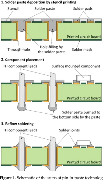
With the rapid development of complex printed circuit boards for advanced appli- cations, electronics components have become smaller, on the one hand, and pin-in-paste technology has come into focus, on the other hand. Pin-in-paste technology provides an advanced assembly method for complex electronic assemblies, where both the surface mounted (SM) and the through-hole (TH) components are assembled at the same time by reflow soldering technology [1]. The steps of the pin-in-paste technology are the same as that of the reflow soldering technology: (1) depositing the solder paste onto the soldering pads and into the plated through-holes of the printed circuit board by stencil printing;
(2) placing the electronic components (also the TH components in this case) into the de- posited solder paste; (3) soldering the components by transporting the printed circuit assembly through a reflow oven, in which the thermal profile is carefully adjusted by setting the proper temperature of individual heating zones (Figure1).
Appl. Sci.2021,11, 4670. https://doi.org/10.3390/app11104670 https://www.mdpi.com/journal/applsci
Appl. Sci.Appl. Sci. 2021, 11, x FOR PEER REVIEW 2021,11, 4670 2 of 11 2 of 11
Figure 1. Schematic of the steps of pin-in-paste technology.
The rapid spread of pin-in-paste technology requires exhaustive analyses of the hole- filling by solder paste and optimization of the stencil printing process. This is of particular importance due to previous researchers reporting that the improper setup of this process could cause 50–60% of the soldering failures [2]. These soldering failures include the for- mation of solder bridges or open joints, if the amount of deposited solder paste is larger or smaller than expected (defined by the volume of the stencil aperture).
Optimizing the stencil printing process can improve both the quality and the relia- bility of solder joints [3]. During the optimization, parameters affecting the process shall be considered, such as the rheological properties of solder paste, the printing speed, and the geometry/orientation of apertures and plated holes for SM and TH components, re- spectively [4,5]. Many research works have proven the correlation between the paste properties and the transfer efficiency of the printing [6,7]. The transfer efficiency charac- terizes the amount of solder paste deposited onto the soldering pads and into the plated through-hole of the printed circuit board. Solder pastes have shear-thinning properties, aiding the flow into the plated through-holes. Solder pastes also have a thixotropic nature for recovery, which allows them to be fixed in the through-holes until the components have been inserted [8].
Many researchers developed numerical models for the stencil printing process to study the influence of the different parameters on the process. Bailey et al. created a 2D numerical model to identify optimal stencil printing parameters for flip-chip assembly [9].
A similar finite volume model was created by Krammer for the stencil printing process to Figure 1.Schematic of the steps of pin-in-paste technology.
The rapid spread of pin-in-paste technology requires exhaustive analyses of the hole- filling by solder paste and optimization of the stencil printing process. This is of particular importance due to previous researchers reporting that the improper setup of this process could cause 50–60% of the soldering failures [2]. These soldering failures include the formation of solder bridges or open joints, if the amount of deposited solder paste is larger or smaller than expected (defined by the volume of the stencil aperture).
Optimizing the stencil printing process can improve both the quality and the reliability of solder joints [3]. During the optimization, parameters affecting the process shall be considered, such as the rheological properties of solder paste, the printing speed, and the geometry/orientation of apertures and plated holes for SM and TH components, respec- tively [4,5]. Many research works have proven the correlation between the paste properties and the transfer efficiency of the printing [6,7]. The transfer efficiency characterizes the amount of solder paste deposited onto the soldering pads and into the plated through- hole of the printed circuit board. Solder pastes have shear-thinning properties, aiding the flow into the plated through-holes. Solder pastes also have a thixotropic nature for recovery, which allows them to be fixed in the through-holes until the components have been inserted [8].
Many researchers developed numerical models for the stencil printing process to study the influence of the different parameters on the process. Bailey et al. created a 2D numerical model to identify optimal stencil printing parameters for flip-chip assembly [9].
A similar finite volume model was created by Krammer for the stencil printing process to investigate the flow of the solder paste and the pressure distribution along the stencil
Appl. Sci.2021,11, 4670 3 of 11
during the printing [10]. Krammer et al. and Durairaj et al. also analyzed the differences between using Newtonian and non-Newtonian fluid properties. They proved that the non-Newtonian behavior of solder pastes should be considered in the modelling [11,12].
Though these works provided valuable insight into the process of stencil printing, their model used a 2D approach and applied steady-state analyses. Due to these limitations, their models could not address the dynamics of hole-filling by the solder paste during stencil printing, which is the most crucial output parameter in the case of pin-in-paste technology. Similarly, the geometrical properties of plated through-holes (e.g., top-view shape) that significantly affect the hole-filling cannot be investigated with these models.
Seo and Kim introduced an analysis method of solder paste flow into the stencil apertures [13]. Their method included a double-step 3D modelling approach due to the limitation in computational resources. First, the pressure distribution along the stencil was obtained by a large-scale model; second, the aperture filling was analyzed in a small- scale model. The limitation of their work is the usage of Newtonian fluid properties throughout their modelling. Thakur et al. created a 3D CFD-based (computational fluid dynamics) model to investigate the flow of solder pastes into the stencil apertures of surface mounted components during printing [14]. They also showed that the non-Newtonian paste properties significantly impact the yield of the stencil printing process; namely, an increasing printing speed will increase the shear stress within the solder paste and, consequently, increase the rate of shear. Since solder pastes are shear-thinning fluids (decreasing viscosity over an increasing rate of shear), an increase in the printing speed will aid the solder paste flow into the stencil apertures. It should be noted that with an increasing printing speed, the solder paste would have less time to fill up the plated holes belonging to through-hole components. Thereby, the increase in printing speed is not as straightforward in pin-in-paste technology as in Thakur’s work. Rusdi et al. studied the flow of solder paste in stencil printing at different aperture sizes and squeegee speeds [15–17]. A transient 3D CFD model was created based on the Volume of Fluid (VOF) method, and the non- Newtonian fluid properties were addressed by Cross’s viscosity model [18]. The results of their model match the experimental measurements with an acceptable error at different aperture sizes, though the error might be reduced further by using Al-Ma’aiteh’s viscosity model [19].
Based on the literature review, none of the works dealt with the hole-filling by solder paste in pin-in-paste technology; all of them investigated the process of stencil printing with a focus on the surface-mounted components. Thus, this research aims to prepare a transient CFD model describing this technology, enabling the analyses of plated through- hole geometries and their effect on hole-filling.
2. Materials and Methods 2.1. The Numerical Model
The numerical model for predicting the hole-filling by the solder paste was created based on the finite volume method. The solder paste can be considered as an incompressible fluid (ρis constant). Therefore, the equation of mass continuity reduces to the volume continuity Equation (1) [20]:
∇ ·u=0 (1)
whereuis the flow velocity. In the range of the generally used printing speeds (20–200 mm/s) and by the high viscosity of solder pastes (over 30–100 Pa·s), the Reynolds number is much lower than 1. This indicates that the Stokes flow Equation (2) can describe the system in a steady state [21]. Additionally, the flow is considered laminar due to the low Reynolds number.
∇p=µ∇2u+f (2)
wherepis the pressure [Pa],ρis the density of the fluid [kg/m3],µis the dynamic viscosity [Pa·s], andfis an applied body force [N], which is 0 in our case.
Appl. Sci.2021,11, 4670 4 of 11
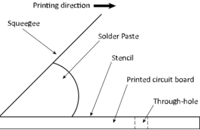
The geometry of the model includes the printing squeegee, the solder paste (fluid), the stencil, and the through-hole(s) of the printed circuit board, as illustrated in Figure2.
Appl. Sci. 2021, 11, x FOR PEER REVIEW 4 of 11
where p is the pressure [Pa], ρ is the density of the fluid [kg/m3], μ is the dynamic viscosity [Pa·s], and f is an applied body force [N], which is 0 in our case.
The geometry of the model includes the printing squeegee, the solder paste (fluid), the stencil, and the through-hole(s) of the printed circuit board, as illustrated in Figure 2.
Figure 2. Schematic of the numerical model for analyzing the hole-filling by the solder paste.
The transient, two-phase model was built using ANSYS Fluent. In the model, the air and the solder paste were considered incompressible. The two-phase model was based on the Volume of Fluid (VOF) method. The movement of the squeegee was addressed by the dynamic meshing method, using the bottom layering technique. The following boundary conditions were applied in the transient model: No-slip wall boundary conditions were applied at the stencil, the squeegee, and the sidewalls of the through-holes. The other walls possessed pressure outlet condition (Figure 3).
Figure 3. Boundary conditions of the numerical model.
Since the heat generated by the moving solder paste is negligible [22], the model was isothermal. Gravitational acceleration was considered as 9.8 m/s2. The dynamic meshing parameters were as follows: the split factor = 0.4, collapse factor = 0.2, cell height = exact value of meshing element size, and the implicit update was activated. The mesh size was optimized by grid analyses and validated by an empirical approach (Section 2.2). The final mesh element size for the fluid area and through-hole was 900 and 200 µm, respectively.
The rheological properties of the solder paste were described by the Al-Ma’aiteh model (3) [19], with parameters valid for a Type-4 solder paste (particle size range is 20–
38 µm).
( )
1( )
2( )
0_1 _1 0_2 _2
1
2 1
( ) (1 )( ) where 1 if
1 0 if 1
t
a n n
a a t
γ γ
η η η η
η β η β η β γ
λ γ γ γ λγ
∞ ∞
∞ − ∞
≤
− −
= + + − + =
+ >
+
(3)
where ηa is the apparent viscosity; η0_1 and η0_2 are the asymptotic viscosity values belong- ing to the zero rate of shear (10 560 and 31 500 Pa·s);
γ
is the rate of shear; η∞_1 and η∞_2 Figure 2.Schematic of the numerical model for analyzing the hole-filling by the solder paste.The transient, two-phase model was built using ANSYS Fluent. In the model, the air and the solder paste were considered incompressible. The two-phase model was based on the Volume of Fluid (VOF) method. The movement of the squeegee was addressed by the dynamic meshing method, using the bottom layering technique. The following boundary conditions were applied in the transient model: No-slip wall boundary conditions were applied at the stencil, the squeegee, and the sidewalls of the through-holes. The other walls possessed pressure outlet condition (Figure3).
Appl. Sci. 2021, 11, x FOR PEER REVIEW 4 of 11
where p is the pressure [Pa], ρ is the density of the fluid [kg/m3], μ is the dynamic viscosity [Pa·s], and f is an applied body force [N], which is 0 in our case.
The geometry of the model includes the printing squeegee, the solder paste (fluid), the stencil, and the through-hole(s) of the printed circuit board, as illustrated in Figure 2.
Figure 2. Schematic of the numerical model for analyzing the hole-filling by the solder paste.
The transient, two-phase model was built using ANSYS Fluent. In the model, the air and the solder paste were considered incompressible. The two-phase model was based on the Volume of Fluid (VOF) method. The movement of the squeegee was addressed by the dynamic meshing method, using the bottom layering technique. The following boundary conditions were applied in the transient model: No-slip wall boundary conditions were applied at the stencil, the squeegee, and the sidewalls of the through-holes. The other walls possessed pressure outlet condition (Figure 3).
Figure 3. Boundary conditions of the numerical model.
Since the heat generated by the moving solder paste is negligible [22], the model was isothermal. Gravitational acceleration was considered as 9.8 m/s2. The dynamic meshing parameters were as follows: the split factor = 0.4, collapse factor = 0.2, cell height = exact value of meshing element size, and the implicit update was activated. The mesh size was optimized by grid analyses and validated by an empirical approach (Section 2.2). The final mesh element size for the fluid area and through-hole was 900 and 200 µm, respectively.
The rheological properties of the solder paste were described by the Al-Ma’aiteh model (3) [19], with parameters valid for a Type-4 solder paste (particle size range is 20–
38 µm).
( )
1( )
2( )
0_1 _1 0_2 _2
1
2 1
( ) (1 )( ) where 1 if
1 0 if 1
t
a n n
a a t
γ γ
η η η η
η β η β η β γ
λ γ γ γ λγ
∞ ∞
∞ − ∞
≤
− −
= + + + − + + = >
(3)
where ηa is the apparent viscosity; η0_1 and η0_2 are the asymptotic viscosity values belong- ing to the zero rate of shear (10 560 and 31 500 Pa·s);
γ
is the rate of shear; η∞_1 and η∞_2 Figure 3.Boundary conditions of the numerical model.Since the heat generated by the moving solder paste is negligible [22], the model was isothermal. Gravitational acceleration was considered as 9.8 m/s2. The dynamic meshing parameters were as follows: the split factor = 0.4, collapse factor = 0.2, cell height = exact value of meshing element size, and the implicit update was activated. The mesh size was optimized by grid analyses and validated by an empirical approach (Section2.2). The final mesh element size for the fluid area and through-hole was 900 and 200µm, respectively.
The rheological properties of the solder paste were described by the Al-Ma’aiteh model (3) [19], with parameters valid for a Type-4 solder paste (particle size range is 20–38µm).
ηa=β(η∞+ η0_1−η∞_1 h1+ λ1γ.ai1
−n1 a
) + (1−β)(η∞+ η0_2−η∞_2
1+ λ2γ.n2) where β
.
γ
=
1 if γ. ≤γ.t 0 if γ. >γ.t
(3)
whereηais the apparent viscosity;η0_1andη0_2are the asymptotic viscosity values belong- ing to the zero rate of shear (10,560 and 31,500 Pa·s);γ. is the rate of shear;η∞_1andη∞_2 are the asymptotic viscosity values belonging to the infinite rate of shear (24 and 30 Pa·s);
Appl. Sci.2021,11, 4670 5 of 11
λ1andλ2are time constants (110 and 340 s);n1,n2andaare dimensionless exponents (0.36, 0.69 and 7); andβis a weighting parameter depending onγ.t(0.0125 s−1).
2.2. Model Validation
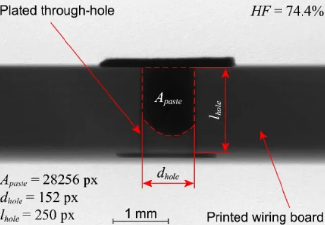
The model was validated by comparing calculated hole-fillings (for various hole diameters and printing speeds) to measured hole-fillings. For the hole-filling measurement, a 1.55 mm thick printed circuit board was designed, which included through-holes with different diameters (0.8, 1.0, 1.1 and 1.4 mm), and solder paste was deposited by stencil printing using different printing speeds (from 20 to 70 mm/s). The solder paste used was a Type-4 (particle size range is 20–38µm) lead-free paste, manufactured by KOKI. The composition of the alloy in the paste was SAC305 (Sn/3Ag/0.5Cu in wt%). The solidus and liquidus points of this alloy are 217 and 220◦C, respectively. The density is 7380 kg/m3, and the (as cast) yield strength and ultimate tensile strength are 26–31 and 30–39 MPa, respectively [23]. The hole-fillings were measured by determining the ratio between the projected area of the solder paste and the projected area of the through-holes in side-view X-ray images. In Figure4, for example, the projected area of the solder paste is 28,256 px, and the projected area of the through-hole is 38,000 px (152·250), resulting in a relative hole-filling of 74.4%.
Appl. Sci. 2021, 11, x FOR PEER REVIEW 5 of 11
are the asymptotic viscosity values belonging to the infinite rate of shear (24 and 30 Pa·s);
λ1 and λ2 are time constants (110 and 340 s); n1, n2 and a are dimensionless exponents (0.36, 0.69 and 7); and β is a weighting parameter depending on
γ
t(0.0125 s-1).2.2. Model validation
The model was validated by comparing calculated hole-fillings (for various hole di- ameters and printing speeds) to measured hole-fillings. For the hole-filling measurement, a 1.55 mm thick printed circuit board was designed, which included through-holes with different diameters (0.8, 1.0, 1.1 and 1.4 mm), and solder paste was deposited by stencil printing using different printing speeds (from 20 to 70 mm/s). The solder paste used was a Type-4 (particle size range is 20–38 µm) lead-free paste, manufactured by KOKI. The composition of the alloy in the paste was SAC305 (Sn/3Ag/0.5Cu in wt%). The solidus and liquidus points of this alloy are 217 and 220 °C, respectively. The density is 7 380 kg/m3, and the (as cast) yield strength and ultimate tensile strength are 26–31 and 30–39 MPa, respectively [23]. The hole-fillings were measured by determining the ratio between the projected area of the solder paste and the projected area of the through-holes in side-view X-ray images. In Figure 4., for example, the projected area of the solder paste is 28 256 px, and the projected area of the through-hole is 38,000 px (152 · 250), resulting in a relative hole-filling of 74.4%.
Figure 4. Measuring the hole-filling by the solder paste on a side-view X-ray image; based on com- paring the projected area of the solder paste to the projected area of the hole (dhole·lhole), the hole- filling is 74.4% in this specific case.
The average error between the calculated (Figure 5) and measured hole-fillings was 6%, whereas the maximum calculation error was 12.8% (Figure 6). The model was consid- ered appropriate for analyzing the hole-filling for various hole shapes and arrangements based on the comparison.
Figure 5. Calculating the hole-filling by the numerical model.
Figure 4. Measuring the hole-filling by the solder paste on a side-view X-ray image; based on comparing the projected area of the solder paste to the projected area of the hole (dhole·lhole), the hole-filling is 74.4% in this specific case.
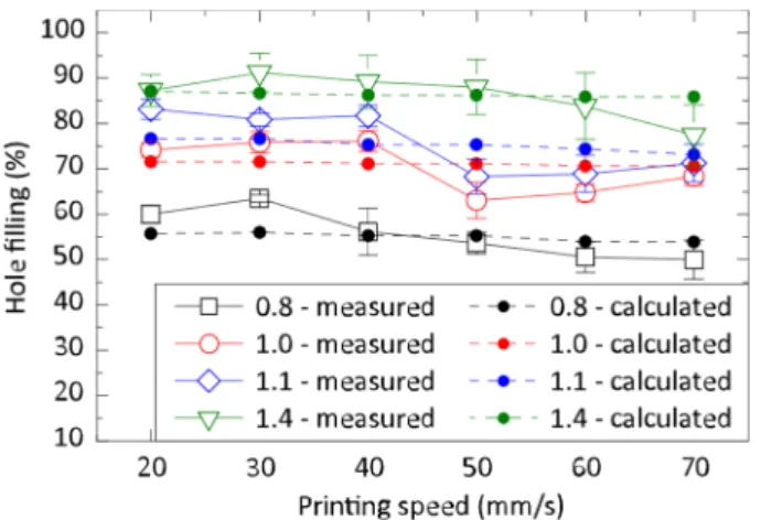
The average error between the calculated (Figure5) and measured hole-fillings was 6%, whereas the maximum calculation error was 12.8% (Figure6). The model was considered appropriate for analyzing the hole-filling for various hole shapes and arrangements based on the comparison.
Appl. Sci. 2021, 11, x FOR PEER REVIEW 5 of 11
are the asymptotic viscosity values belonging to the infinite rate of shear (24 and 30 Pa·s);
λ1 and λ2 are time constants (110 and 340 s); n1, n2 and a are dimensionless exponents (0.36, 0.69 and 7); and β is a weighting parameter depending on
γ
t(0.0125 s-1).2.2. Model validation
The model was validated by comparing calculated hole-fillings (for various hole di- ameters and printing speeds) to measured hole-fillings. For the hole-filling measurement, a 1.55 mm thick printed circuit board was designed, which included through-holes with different diameters (0.8, 1.0, 1.1 and 1.4 mm), and solder paste was deposited by stencil printing using different printing speeds (from 20 to 70 mm/s). The solder paste used was a Type-4 (particle size range is 20–38 µm) lead-free paste, manufactured by KOKI. The composition of the alloy in the paste was SAC305 (Sn/3Ag/0.5Cu in wt%). The solidus and liquidus points of this alloy are 217 and 220 °C, respectively. The density is 7 380 kg/m3, and the (as cast) yield strength and ultimate tensile strength are 26–31 and 30–39 MPa, respectively [23]. The hole-fillings were measured by determining the ratio between the projected area of the solder paste and the projected area of the through-holes in side-view X-ray images. In Figure 4., for example, the projected area of the solder paste is 28 256 px, and the projected area of the through-hole is 38,000 px (152 · 250), resulting in a relative hole-filling of 74.4%.
Figure 4. Measuring the hole-filling by the solder paste on a side-view X-ray image; based on com- paring the projected area of the solder paste to the projected area of the hole (dhole·lhole), the hole- filling is 74.4% in this specific case.
The average error between the calculated (Figure 5) and measured hole-fillings was 6%, whereas the maximum calculation error was 12.8% (Figure 6). The model was consid- ered appropriate for analyzing the hole-filling for various hole shapes and arrangements based on the comparison.
Figure 5. Calculating the hole-filling by the numerical model.
Figure 5.Calculating the hole-filling by the numerical model.
Appl. Sci.2021,11, 4670 6 of 11
Appl. Sci. 2021, 11, x FOR PEER REVIEW 6 of 11
Figure 6. Empirical and calculated hole-filling by the solder paste; length of the holes in z-direction was 1.55 mm, and diameters were 0.8, 1.0, 1.1, 1.4 mm; average calculation error is 6%, and maxi- mum calculation error is 12.8%.
3. Results and Discussion
The interaction between a set of through-holes (7 pcs.) was analyzed for two cases: a) the through-holes were arranged in parallel with the travelling direction of the printing squeegee; b) the through-holes were arranged perpendicular to it. The diameter and the z-dimension of the holes were 1.1 and 1.55 mm, respectively. These holes were distributed evenly, at distances of 2.54 mm (Figure 7), similarly to a lead arrangement of a through- hole serial connector.
Figure 7. Numerical model, where the through-holes are arranged in parallel with the travelling direction of the squeegee. The seven consecutive through-holes are distributed evenly at distances of 2.54 mm
As expected, there was no interaction between the holes, and the hole-filling was the same for all through-holes when they were arranged perpendicular to the travelling di- rection (in parallel with the line) of the printing squeegee. However, an interaction be- tween the holes was found when they were arranged in parallel with the direction of the squeegee movement. A clear and gradual reduction in the hole-filling was observed, which became more intensive at higher printing speeds. The differences in hole-filling between the first and the seventh hole were 2.4% and 9.2% for the printing speeds of 20 and 120 mm/s, respectively (Figure 8).
Figure 6.Empirical and calculated hole-filling by the solder paste; length of the holes inz-direction was 1.55 mm, and diameters were 0.8, 1.0, 1.1, 1.4 mm; average calculation error is 6%, and maximum calculation error is 12.8%.
3. Results and Discussion
The interaction between a set of through-holes (7 pcs.) was analyzed for two cases: (a) the through-holes were arranged in parallel with the travelling direction of the printing squeegee; (b) the through-holes were arranged perpendicular to it. The diameter and the z-dimension of the holes were 1.1 and 1.55 mm, respectively. These holes were distributed evenly, at distances of 2.54 mm (Figure7), similarly to a lead arrangement of a through-hole serial connector.
Appl. Sci. 2021, 11, x FOR PEER REVIEW 6 of 11
Figure 6. Empirical and calculated hole-filling by the solder paste; length of the holes in z-direction was 1.55 mm, and diameters were 0.8, 1.0, 1.1, 1.4 mm; average calculation error is 6%, and maxi- mum calculation error is 12.8%.
3. Results and Discussion
The interaction between a set of through-holes (7 pcs.) was analyzed for two cases: a) the through-holes were arranged in parallel with the travelling direction of the printing squeegee; b) the through-holes were arranged perpendicular to it. The diameter and the z-dimension of the holes were 1.1 and 1.55 mm, respectively. These holes were distributed evenly, at distances of 2.54 mm (Figure 7), similarly to a lead arrangement of a through- hole serial connector.
Figure 7. Numerical model, where the through-holes are arranged in parallel with the travelling direction of the squeegee. The seven consecutive through-holes are distributed evenly at distances of 2.54 mm
As expected, there was no interaction between the holes, and the hole-filling was the same for all through-holes when they were arranged perpendicular to the travelling di- rection (in parallel with the line) of the printing squeegee. However, an interaction be- tween the holes was found when they were arranged in parallel with the direction of the squeegee movement. A clear and gradual reduction in the hole-filling was observed, which became more intensive at higher printing speeds. The differences in hole-filling between the first and the seventh hole were 2.4% and 9.2% for the printing speeds of 20 and 120 mm/s, respectively (Figure 8).
Figure 7.Numerical model, where the through-holes are arranged in parallel with the travelling direction of the squeegee. The seven consecutive through-holes are distributed evenly at distances of 2.54 mm.
As expected, there was no interaction between the holes, and the hole-filling was the same for all through-holes when they were arranged perpendicular to the travelling direction (in parallel with the line) of the printing squeegee. However, an interaction between the holes was found when they were arranged in parallel with the direction of the squeegee movement. A clear and gradual reduction in the hole-filling was observed, which became more intensive at higher printing speeds. The differences in hole-filling between the first and the seventh hole were 2.4% and 9.2% for the printing speeds of 20 and 120 mm/s, respectively (Figure8).
The hole-filling was analyzed further to find a possible explanation for the differences in the filling. The rate of shear during the printing within the solder paste was analyzed by comparing the cases of having one single hole or seven consecutive holes (Figure9—the printing squeegee travelled till the first through-hole). It was found that placing the holes after one another disturbs the flow-field, and the rate of shear is lower (by up to 5–6%) on the stencil surface compared to the case utilizing a single hole (Figure10).
Appl. Sci.2021,11, 4670 7 of 11
Appl. Sci. 2021, 11, x FOR PEER REVIEW 7 of 11
Figure 8. Hole-filling by the solder paste in the seven consecutive holes at different printing speeds.
The hole-filling was analyzed further to find a possible explanation for the differ- ences in the filling. The rate of shear during the printing within the solder paste was ana- lyzed by comparing the cases of having one single hole or seven consecutive holes (Figure 9—the printing squeegee travelled till the first through-hole). It was found that placing the holes after one another disturbs the flow-field, and the rate of shear is lower (by up to 5–6%) on the stencil surface compared to the case utilizing a single hole (Figure 10).
(a) (b)
Figure 9. Analyzing the interaction between through-holes and the hole-filling (printing speed was 120 mm/s): (a) single- hole model; (b) model including seven consecutive through-holes.
Figure 10. Rate of shear on the surface of the stencil at the proximity of the through-holes for the printing speed of 120 mm/s.
Since solder pastes are shear-thinning fluid, a decrease in shear rate yields an increase in the viscosity (Figure 11a). This increase in viscosity means a larger reluctance of the Figure 8.Hole-filling by the solder paste in the seven consecutive holes at different printing speeds.
Appl. Sci. 2021, 11, x FOR PEER REVIEW 7 of 11
Figure 8. Hole-filling by the solder paste in the seven consecutive holes at different printing speeds.
The hole-filling was analyzed further to find a possible explanation for the differ- ences in the filling. The rate of shear during the printing within the solder paste was ana- lyzed by comparing the cases of having one single hole or seven consecutive holes (Figure 9—the printing squeegee travelled till the first through-hole). It was found that placing the holes after one another disturbs the flow-field, and the rate of shear is lower (by up to 5–6%) on the stencil surface compared to the case utilizing a single hole (Figure 10).
(a) (b)
Figure 9. Analyzing the interaction between through-holes and the hole-filling (printing speed was 120 mm/s): (a) single- hole model; (b) model including seven consecutive through-holes.
Figure 10. Rate of shear on the surface of the stencil at the proximity of the through-holes for the printing speed of 120 mm/s.
Since solder pastes are shear-thinning fluid, a decrease in shear rate yields an increase in the viscosity (Figure 11a). This increase in viscosity means a larger reluctance of the Figure 9. Analyzing the interaction between through-holes and the hole-filling (printing speed was 120 mm/s):
(a) single-hole model; (b) model including seven consecutive through-holes.
Appl. Sci. 2021, 11, x FOR PEER REVIEW 7 of 11
Figure 8. Hole-filling by the solder paste in the seven consecutive holes at different printing speeds.
The hole-filling was analyzed further to find a possible explanation for the differ- ences in the filling. The rate of shear during the printing within the solder paste was ana- lyzed by comparing the cases of having one single hole or seven consecutive holes (Figure 9—the printing squeegee travelled till the first through-hole). It was found that placing the holes after one another disturbs the flow-field, and the rate of shear is lower (by up to 5–6%) on the stencil surface compared to the case utilizing a single hole (Figure 10).
(a) (b)
Figure 9. Analyzing the interaction between through-holes and the hole-filling (printing speed was 120 mm/s): (a) single- hole model; (b) model including seven consecutive through-holes.
Figure 10. Rate of shear on the surface of the stencil at the proximity of the through-holes for the printing speed of 120 mm/s.
Since solder pastes are shear-thinning fluid, a decrease in shear rate yields an increase in the viscosity (Figure 11a). This increase in viscosity means a larger reluctance of the
Figure 10.Rate of shear on the surface of the stencil at the proximity of the through-holes for the printing speed of 120 mm/s.
Since solder pastes are shear-thinning fluid, a decrease in shear rate yields an increase in the viscosity (Figure11a). This increase in viscosity means a larger reluctance of the material to flow into the through-holes. In addition, the disturbance in the flow-field resulted in a decrease in pressure in proximity to the through-holes (Figure11b).
Appl. Sci.2021,11, 4670 8 of 11
ChemEngineering 2021, 5, x. https://doi.org/10.3390/xxxxx www.mdpi.com/journal/chemengineering Figure 11.Comparing the cases utilizing a single hole or multiple holes in the printed wiring board (printing speed was 120 mm/s): (a) dynamic viscosity of the solder paste; (b) pressure along the line of the stencil.
The hole-filling during stencil printing can be approximated by the Hagen–Poiseuille Equation (4). This states that the volumetric flow rate within a channel depends on the dynamic viscosity of the fluid, on the pressure gradient in the channel, and on the radius of the channel [24]:
Q=−π 8η
∂p
∂z
·R4 (4)
whereQis the volumetric flow rate,Ris the radius of the hole, and∂p/∂zis the pressure gradient. From this expression, one can deduct that an increase in the pressure (and thus in the pressure gradient) and/or a decrease in the dynamic viscosity yields a lower volumetric flow rate in a channel, implying lower hole-filling by the solder paste in pin-in-paste technology. This decrease in hole-filling can be considered either in the design phase of the product or the manufacturing. Through-hole connectors should be oriented perpendicular to the travelling direction of the printing squeegee to minimize the interaction between the holes and the variation in the hole-filling by the solder paste. If connectors are oriented in parallel with the squeegee movement (due to design considerations), providing additional solder paste to the last holes (where a lower filling is expected) would be required, e.g., by utilizing pre-form (pre-shaped and fluxless) solders.
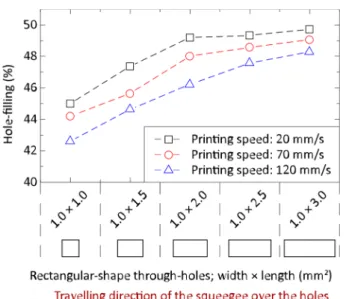
The effect of hole shape on the hole-filling was also investigated. Oblong-shaped through-holes were analyzed by utilizing rectangular-shaped holes in the numerical model.
Five different shapes were investigated, and the linear dimensions of the holes were varied at 1.0×1.0, 1.0×1.5, 1.0×2, 1.0×2.5, and 1.0×3.0 mm (Figure12). The holes with different shapes were also oriented in two directions: perpendicular to and in parallel with the travelling direction of the printing squeegee. Note that the dimension of the through- holes inz-direction was increased from 1.55 to 4 mm, since in the case of larger holes (e.g., 1.0×2 mm), a filling larger than 1.55 mm was expected. The filling of rectangular-shaped through-holes was investigated at three different printing velocities (20, 70, and 120 mm/s).
Similarly to the previous case, the size of the rectangular holes (1 × 1 mm . . . 1×3 mm) did not affect the hole-filling significantly if the holes were oriented perpen- dicular to the travelling direction of the squeegee. However, a significant increase in the hole-filling was found, depending on the hole size, if the holes were oriented in parallel with the squeegee movement. The differences in the hole-filling between the smallest (1× 1 mm) and the largest (1×3 mm) holes were 13%, 11%, and 10% for the printing velocities of 120, 70, and 20 mm/s, respectively (Figure12).
Appl. Sci.2021,11, 4670 9 of 11
Appl. Sci. 2021, 11, x FOR PEER REVIEW 9 of 11
Figure 12. Hole-filling as a function of rectangular-shaped through-holes at different printing speeds (note that the dimension of the holes in z-direction was 4 mm).
The dynamics of hole-filling were analyzed and compared between the cases of ori- enting a through-hole perpendicular to or in parallel with the travelling direction of the printing squeegee. It was found that the through-holes were filled almost linearly over time (Figure 13). However, the pressure on the solder paste increases exponentially as the squeegee travels over the through-hole [10,11]. The amount of solder paste also gradually increases in the hole, introducing resistance against the filling and resulting in almost lin- ear fill-dynamics. This implies that the hole-filling depends mainly on time spent by the printing squeegee over the through-holes (considering identical process and material pa- rameters). Therefore, larger hole-filling is expected if the rectangular- or oblong-shaped through-holes are oriented in parallel with the travelling direction of the squeegee. Simi- larly, gradually larger hole-filling is anticipated if the linear size of the holes is extending in parallel with the squeegee movement. The orientation of oblong-shaped through-holes can be designed according to the solder paste requirement for a specific component lead geometry. If the component leads are smaller for a particular oblong-shaped through- hole, thus requiring more solder paste to form appropriate solder joints, the respective through-holes should be oriented in a parallel direction with the squeegee movement. If the lead sizes are larger, the through-holes can be oriented perpendicular to the squeegee movement.
Figure 13. Comparing the hole-filling of rectangular-shaped holes (1 × 2 mm) oriented in parallel with or perpendicular to the travelling direction of the printing squeegee (printing speed was 120 mm/s).
Figure 12.Hole-filling as a function of rectangular-shaped through-holes at different printing speeds (note that the dimension of the holes inz-direction was 4 mm).
The dynamics of hole-filling were analyzed and compared between the cases of orienting a through-hole perpendicular to or in parallel with the travelling direction of the printing squeegee. It was found that the through-holes were filled almost linearly over time (Figure13). However, the pressure on the solder paste increases exponentially as the squeegee travels over the through-hole [10,11]. The amount of solder paste also gradually increases in the hole, introducing resistance against the filling and resulting in almost linear fill-dynamics. This implies that the hole-filling depends mainly on time spent by the printing squeegee over the through-holes (considering identical process and material parameters). Therefore, larger hole-filling is expected if the rectangular- or oblong-shaped through-holes are oriented in parallel with the travelling direction of the squeegee. Similarly, gradually larger hole-filling is anticipated if the linear size of the holes is extending in parallel with the squeegee movement. The orientation of oblong-shaped through-holes can be designed according to the solder paste requirement for a specific component lead geometry. If the component leads are smaller for a particular oblong- shaped through-hole, thus requiring more solder paste to form appropriate solder joints, the respective through-holes should be oriented in a parallel direction with the squeegee movement. If the lead sizes are larger, the through-holes can be oriented perpendicular to the squeegee movement.
Appl. Sci. 2021, 11, x FOR PEER REVIEW 9 of 11
Figure 12. Hole-filling as a function of rectangular-shaped through-holes at different printing speeds (note that the dimension of the holes in z-direction was 4 mm).
The dynamics of hole-filling were analyzed and compared between the cases of ori- enting a through-hole perpendicular to or in parallel with the travelling direction of the printing squeegee. It was found that the through-holes were filled almost linearly over time (Figure 13). However, the pressure on the solder paste increases exponentially as the squeegee travels over the through-hole [10,11]. The amount of solder paste also gradually increases in the hole, introducing resistance against the filling and resulting in almost lin- ear fill-dynamics. This implies that the hole-filling depends mainly on time spent by the printing squeegee over the through-holes (considering identical process and material pa- rameters). Therefore, larger hole-filling is expected if the rectangular- or oblong-shaped through-holes are oriented in parallel with the travelling direction of the squeegee. Simi- larly, gradually larger hole-filling is anticipated if the linear size of the holes is extending in parallel with the squeegee movement. The orientation of oblong-shaped through-holes can be designed according to the solder paste requirement for a specific component lead geometry. If the component leads are smaller for a particular oblong-shaped through- hole, thus requiring more solder paste to form appropriate solder joints, the respective through-holes should be oriented in a parallel direction with the squeegee movement. If the lead sizes are larger, the through-holes can be oriented perpendicular to the squeegee movement.
Figure 13. Comparing the hole-filling of rectangular-shaped holes (1 × 2 mm) oriented in parallel with or perpendicular to the travelling direction of the printing squeegee (printing speed was 120 mm/s).
Figure 13.Comparing the hole-filling of rectangular-shaped holes (1×2 mm) oriented in parallel with or perpendicular to the travelling direction of the printing squeegee (printing speed was 120 mm/s).
Appl. Sci.2021,11, 4670 10 of 11
4. Conclusions
A computational fluid dynamics model was established aiming to investigate the stencil printing process of the pin-in-paste technology. The hole-filling by the solder paste was analyzed for the case when a set of consecutive holes was designed in the printed circuit board. The consecutive holes disturb the flow-field and affect the hole-filling if they are arranged in parallel with the travelling direction of the printing squeegee. Similarly, the hole-filling is affected by the orientation of oblong-shaped through-holes. The variations in the hole-filling can be considered either in the design phase of the electronic products or the manufacturing processes. Through-hole connectors should be oriented perpendicular to the travelling direction of the printing squeegee to minimize the interaction between the holes and the variation in hole-filling. If this is not feasible, and circular lead connectors are oriented parallel with the squeegee movement, providing additional solder paste to the last holes might be required, e.g., by utilizing pre-form (pre-shaped and fluxless) solders. The soldering failures in pin-in-paste technology can be reduced by these early design-phase considerations, and the first-pass yield of electronic soldering technologies can be enhanced.
Author Contributions:Conceptualization, T.I.A.-M. and O.K.; methodology, O.K.; validation, T.I.A.- M., O.K., and B.I.; formal analysis, T.I.A.-M. and O.K.; investigation, T.I.A.-M. and O.K.; writing—
original draft preparation, T.I.A.-M., O.K., and B.I.; writing, T.I.A.-M., O.K., and B.I.; supervision, O.K. and B.I. All authors have read and agreed to the published version of the manuscript.
Institutional Review Board Statement:Not applicable.
Informed Consent Statement:Not applicable.
Data Availability Statement:The data are part of an ongoing project.
Acknowledgments: This paper was supported by the János Bolyai Research Scholarship of the Hungarian Academy of Sciences; theÚNKP-20-5 New National Excellence Program of the Ministry for Innovation and Technology from the source of the National Research, Development and Inno- vation Fund; and the National Research Development and Innovation Office Hungary (NKFIH), project FK127970.
Conflicts of Interest:The authors declare no conflict of interest.
References
1. Martinek, P.; Krammer, O. Analysing machine learning techniques for predicting the hole-filling in pin-in-paste technology.
Comput. Ind. Eng.2019,136, 187–194. [CrossRef]
2. Tsai, T.N. Modeling and optimization of stencil printing operations: A comparison study.Comput. Ind. Eng.2008,54, 374–389.
[CrossRef]
3. Hirman, M.; Steiner, F. Optimization of solder paste quantity considering the properties of solder joints.Solder. Surf. Mt. Technol.
2017,29, 15–22. [CrossRef]
4. Nguty, T.A.; Ekere, N.N.; Adebayo, A. Correlating solder paste composition with stencil printing performance. In Proceedings of the IEEE/CPMT International Electronics Manufacturing Technology (IEMT) Symposium, San Jose, CA, USA, 16–18 July 2003;
pp. 304–312. [CrossRef]
5. Haslehurst, L.; Ekere, N.N. Parameter interactions in stencil printing of solder pastes. J. Electron. Manuf. 1996,6, 307–316.
[CrossRef]
6. Amalu, E.H.; Ekere, N.N.; Mallik, S. Evaluation of rheological properties of lead-free solder pastes and their relationship with transfer efficiency during stencil printing process.Mater. Des.2011,32, 3189–3197. [CrossRef]
7. Durairaj, R.; Ramesh, S.; Mallik, S.; Seman, A.; Ekere, N.N. Rheological characterization and printing performance of Sn/Ag/Cu solder pastes.Mater. Des.2009,30, 3812–3818. [CrossRef]
8. Rusdi, M.S.; Abdullah, M.Z.; Chellvarajoo, S.; Abdul Aziz, M.S.; Abdullah, M.K.; Rethinasamy, P.; Veerasamy, S.; Santhanasamy, D.G. Stencil printing process performance on various aperture size and optimization for lead-free solder paste.Int. J. Adv. Manuf.
Technol.2019,102, 3369–3379. [CrossRef]
9. Bailey, C.; Lu, H.; Glinski, G.; Wheeler, D.; Hamilton, P.; Hendriksen, M.; Smith, B. Using computer models to identify optimal conditions for flip-chip assembly and reliability.Circuit World2002,28, 14–20. [CrossRef]
10. Krammer, O. Finite volume modelling of stencil printing process. In Proceedings of the 2014 IEEE 20th International Symposium for Design and Technology in Electronic Packaging (SIITME 2014), Bucharest, Romania, 23–26 October 2014; pp. 79–82. [CrossRef]
Appl. Sci.2021,11, 4670 11 of 11
11. Krammer, O.; Varga, B.; Busek, D. Investigating the effect of solder paste viscosity change on the pressure during stencil printing.
In Proceedings of the 2016 IEEE 22nd International Symposium for Design and Technology in Electronic Packaging (SIITME 2016), Oradea, Romania, 20–23 October 2016; pp. 36–39. [CrossRef]
12. Durairaj, R.; Jackson, G.J.; Ekere, N.N.; Glinski, G.; Bailey, C. Correlation of solder paste rheology with computational simulations of the stencil printing process.Solder. Surf. Mt. Technol.2002,14, 11–17. [CrossRef]
13. Seo, W.S.; Kim, J.B. Filling analyses of solder paste in the stencil printing process and its application to process design.Solder.
Surf. Mt. Technol.2013,25, 145–154. [CrossRef]
14. Thakur, V.; Mallik, S.; Vuppala, V. CFD Simulation of Solder Paste Flow and Deformation Behaviours during Stencil Printing Process.Int. J. Recent Adv. Mech. Eng.2015,4, 1–13. [CrossRef]
15. Rusdi, M.S.; Abdullah, M.Z.; Abdul Aziz, M.S.; Abdullah@Harun, M.K.; Chellvarajoo, S.; Husin, A.; Rethinasamy, P.; Veerasamy, S. Multiphase Flow in Solder Paste Stencil Printing Process using CFD approach.J. Adv. Res. Fluid Mech. Therm. Sci.2020,46, 147–152. Available online:http://akademiabaru.com/submit/index.php/arfmts/article/view/2212(accessed on 22 April 2021).
16. Rusdi, M.S.; Abdullah, M.Z.; Abdul Aziz, M.S.; Abdullah, M.K.; Ishak, M.H.H.; Hwa, Y.K.; Rethinasamy, P.; Veerasamy, S.;
Santhanasamy, D.G. SAC105 Stencil Printing Process using Cross Viscosity Model.J. Adv. Res. Fluid Mech. Therm. Sci.2020,54, 70–77. Available online:https://www.akademiabaru.com/submit/index.php/arfmts/article/view/2436(accessed on 22 April 2021).
17. Rusdi, M.S.; Abdullah, M.Z.; Ishak, M.H.H.; Abdul Aziz, M.S.; Abdullah, M.K.; Rethinasamy, P.; Jalar, A. Three-dimensional CFD simulation of the stencil printing performance of solder paste.Int. J. Adv. Manuf. Technol.2020,108, 3351–3359. [CrossRef]
18. Ferguson, J.; Kemblowski, Z.Applied Fluid Rheology; Springer: Berlin/Heidelberg, Germany, 1991; ISBN 978-1-85166-588-4.
19. Al-Ma’aiteh, T.I.; Krammer, O. Non-Newtonian numerical modelling of solder paste viscosity measurement.Solder. Surf. Mt.
Technol.2019,31, 176–180. [CrossRef]
20. Illés, B.; Géczy, A.; Skwarek, A.; Busek, D. Effects of substrate thermal properties on the heat transfer coefficient of vapour phase soldering.Int. J. Heat Mass Transf.2016,101, 69–75. [CrossRef]
21. Constantinscu, V.N.Laminar viscous flow; Springer: New York, NY, USA, 1995; ISBN 978-1-4612-8706-3.
22. Mannan, S.H.; Ekere, N.N.; Ismail, I.; Currie, M.A. Flow processes in solder paste during stencil printing for SMT assembly.J.
Mater. Sci. Mater E1995,6, 34–42. [CrossRef]
23. Sabri, M.F.M.; Shnawah, D.A.; Badruddin, I.A.; Said, S.B.M.; Che, F.X.; Ariga, T. Microstructural stability of Sn–1Ag–0.5Cu–xAl (x = 1, 1.5, and 2wt.%) solder alloys and the effects of high-temperature aging on their mechanical properties.Mater. Charact.
2013,78, 129–143. [CrossRef]
24. Kirby, B.J.Micro- and Nanoscale Fluid Mechanics: Transport in Microfluidic Devices; Cambridge University Press: New York, NY, USA, 2010; ISBN 978-0-521-11903-0.
![[1] [Introduction to Surface-Mount Technology] [Oliver Krammer]](data:image/gif;base64,R0lGODlhAQABAIAAAP///wAAACH5BAEAAAAALAAAAAABAAEAAAICRAEAOw==)