IOP Conference Series: Materials Science and Engineering
PAPER • OPEN ACCESS
Effects of plasma nitriding on tempered steel
To cite this article: D Kovács et al 2018 IOP Conf. Ser.: Mater. Sci. Eng. 426 012027
View the article online for updates and enhancements.
This content was downloaded from IP address 152.66.35.17 on 29/01/2019 at 08:43
1234567890‘’“”
11th Hungarian Conference on Materials Science IOP Publishing
IOP Conf. Series: Materials Science and Engineering 426 (2018) 012027 doi:10.1088/1757-899X/426/1/012027
Effects of plasma nitriding on tempered steel
D Kovács1, A Kemény1, J Dobránszky2 and I Quintana3
1 Budapest University of Technology and Economics, Faculty of Mechanical Engi- neering, Department of Materials Science and Technology, Budapest, Hungary
2 MTA–BME Research Group for Composite Science and Technology, Budapest, Hungary
3 IK4-Tekniker, Parke Teknologikoa, Goenaga, Spain E-mail: dorina@eik.bme.hu
Abstract. Conventional plasma nitriding is highly widespread in the industry, but it has essential problems such as edge effect and hollow cathode effect. These problems induced the develop- ment of active screen plasma nitriding (ASPN) where the plasma forms on the active screen instead of the sample, which is completely insulated. However, this arrangement does not work with large furnaces, so the usage of bias voltage is necessary in industrial circumstances. In this experiment, the effects of different biases were examined, specifically the hardness, layer thick- ness, formed phases and the diffusion of nitrogen. In conclusion, the 20 % bias had the best effects on the sample with the defined nitriding parameters in this research.
1. Introduction
Plasma nitriding is a thermochemical surface treatment which can improve the hardness and the wear resistance of the steel. When the nitrogen – hydrogen gas mixture enters the process chamber, the gas becomes ionized between the anode (furnace wall) and the cathode (workpiece). The positively charged ions bombard the surface of the piece which heats up [1–3]. This issue a glow discharge when the par- ticles absorb into the surface of the material. The three most important factors of the treatment are the pressure, the high voltage and the ratio of the used gas mixture. The temperature and time of the treat- ment also influences the properties of the nitride layer.
The direct current plasma nitriding (DCPN) is a traditional surface treatment over 40 years. The DCPN technology has different shortcomings which cause a damage on the parts, such as ‘edge effect’
or ‘hollow cathode effect’ [3–5]. The active screen plasma nitriding was developed to solve the previous problems. In this technology the plasma is produced on the screen, not directly on the workpiece there- fore it causes a more homogenous surface [6–8]. In this case the worktable is isolated from the place of the voltage, so heating of the ASPN is slow. To increase this process the components are in a floating potential or a relative lower bias voltage [8, 9].
2. Materials and methods
The materials used in this study are tempered 42CrMo4 type low alloy steel and annealed C45 type carbon steel, their chemical compositions are shown in table 1. The sample disks were 20 mm in diam- eter and 6 mm in thickness. The sample’s surface was mechanically ground with 80 to 2500-grit SiC emery paper, finely polished with 3 m diamond suspension. They were cleaned in acetone and dried
2
1234567890‘’“”
11th Hungarian Conference on Materials Science IOP Publishing
IOP Conf. Series: Materials Science and Engineering 426 (2018) 012027 doi:10.1088/1757-899X/426/1/012027
Table 1. Chemical composition of materials in wt.%
Steel C Si Mn P S Cr Mo
42CrMo4 0.38–0.45 ≤ 0.4 0.6–0.9 ≤ 0.025 ≤ 0.035 0.9–1.2 1.5–0.3 C45 0.42–0.5 ≤ 0.4 0.5–0.8 ≤ 0.045 ≤ 0.045 ≤ 0.4 ≤ 0.1 The plasma nitriding system was built by own plan. Parameters easily set to the different methods.
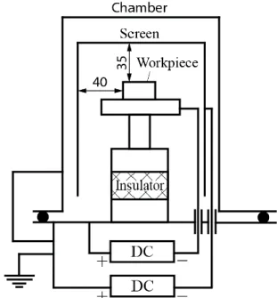
Figure 1 shows the schematic workplace of the chamber. The active screen was made of unalloyed 1.0330 type steel. The dimension is 100×85 mm with 5×8 mm holes and centers. All treatments were carried out using the same parameters as shown in Table 2 and following the same procedures.
Bias voltage was adapting to the main voltage. The bias is 10 %, 20 % of the main voltage at the same parameters of the process. After the nitriding, free cooling started to the turning of the plasma. The workpiece was cooling down from the process temperature to the room temperature under the nitriding pressure.
Figure 1. Schematic model of the nitriding chamber (biased arrangement) Table 2. Parameters of plasma nitriding
Voltage (V)
Current (A)
Gas mixture N2:H2 (%)
Temperature (°C)
Pressure (torr)
Time (h)
490 – 540 0,9 – 1,5 25:75 490 2,8 4
Optical microscope and scanning electron microscope were used to examine morphology and meas- ure thickness of nitrided layer. The hardness profile was determined by micro Vickers indenter with a load of 50g. The phase composition of the compound layer on the surface was determined by X-ray diffractometer (XRD) using CuKα radiation [10–15] .
1234567890‘’“”
11th Hungarian Conference on Materials Science IOP Publishing
IOP Conf. Series: Materials Science and Engineering 426 (2018) 012027 doi:10.1088/1757-899X/426/1/012027
3. Results and discussion
3.1. Surface analysis by optical microscope
First, DCPN and ASPN treated C45 samples were compared. The edge effect was observed at the treat- ment of DCPN as it can be seen in Figure 2a) and b). The well-visible erosion ring has reduced the hardness toward the centre of the sample, while the microhardness value is much higher in the edge area, due to thermal gradient, as it was presented in another work; this causes unequal microhardness values on the surface [6]. The nitride layer depth is unequal in the erosion zone compared to the centre.
Figure 2. Discoloured surface after plasma nitriding a) C45 – DCPN, b) C45 – ASPN, c) 42CrMo4 - biased 3.2. Hardness and thickness measurements
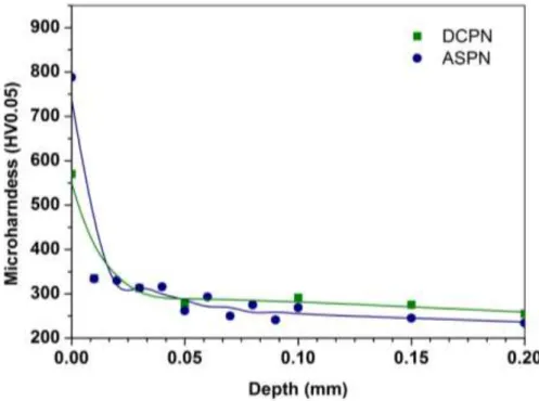
Figures 3 and 4 show the cross-sectional hardness distribution of the different samples. The compound layer thickness was measured by using the distance measurement tool of the scanning electron micro- scope. The hardness decreased considerably toward the core of the material in each condition. The sam- ples of steel C45 show a significant hardness drop after the compound layer while the samples of steel 42CrMo4 have smooth transition to the core hardness. This means that the diffusion zone is substantially larger with the alloyed steel. The effect of bias is also visible on the hardness profile. As higher percent- age of the voltage was used as bias, higher surface hardness and thicker compound layer was formed.
In proportion to DCPN, the use of bias cause significant increasing of hardness.
Figure 3. Two hardness profiles of steel C45
a) b) c)
4
1234567890‘’“”
11th Hungarian Conference on Materials Science IOP Publishing
IOP Conf. Series: Materials Science and Engineering 426 (2018) 012027 doi:10.1088/1757-899X/426/1/012027
Figure 4. Hardness profiles of steel 42CrMo4
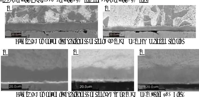
Scanning electron microscope was used to determine the depth of the compound layer. Figure 5 shows the cross section of two C45 steel samples. The layer thickness was 8.6 µm with DCPN and 5.5 µm with ASPN, respectively.
Figure 6 shows the cross section of the 42CrMo4 type low alloy steel samples. The layer thickness was 15 µm with DCPN, 11.2 µm with 10% bias and 15.5 µm with 20% bias.
Figure 5. Compound layer thickness of steel C45 a) DCPN, b) ASPN treated samples
Figure 6. Compound layer thickness of steel 42CrMo4 a) DCPN, b) using 10% Bias, c) using 20% Bias treated samples
3.3. X-Ray diffraction analysis
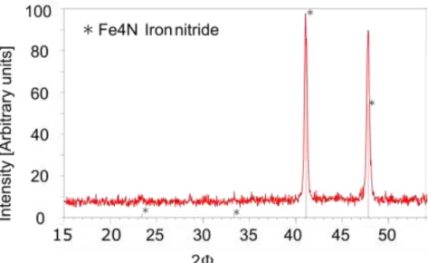
DC plasma nitriding samples were investigated by XRD analysis. Figure 7-8 contain the diffraction pattern of C45 and 42CrMo4. γ’ phase, as Fe4N, was formed on both sample with the same intensity [15]. As observed in Figure 8, magnetite is also formed on the surface. It means some oxygen is present in the vacuum chamber, but this rate is minimal, it didn’t influence the compound layer.
a) b)
a) b) c)
1234567890‘’“”
11th Hungarian Conference on Materials Science IOP Publishing
IOP Conf. Series: Materials Science and Engineering 426 (2018) 012027 doi:10.1088/1757-899X/426/1/012027
Figure 7. X-ray diffractogram of DC plasma nitrided steel C45
Figure 8. X-ray diffractogram of DC plasma nitrided steel 42CrMo4
4. Conclusions
The annealed C45 type carbon steel is not a typical grade for plasma nitriding. The compound layer thickness is formed on the surface like as other tempered steel, but the depth of the diffusion zone is lower than the other case.
The effect of bias on steel 42CrMo4 was analysed with different methods. The results show that higher hardness can be reached with higher bias voltage. The hardness profile also shows that the alloyed steel has a much thicker diffusion zone than the unalloyed. With higher bias, slightly thicker compound layer is formed which can be examined well using SEM.
Acknowledgments
The authors would like to acknowledge the IK4-Tekniker for their support and access to their facilities.
6
1234567890‘’“”
11th Hungarian Conference on Materials Science IOP Publishing
IOP Conf. Series: Materials Science and Engineering 426 (2018) 012027 doi:10.1088/1757-899X/426/1/012027
References
[1] Pye D 2003 Practical Nitriding and Ferritic Nitrocarburizing (Ohio: ASM International) [2] Hossein A and Behrangi S 1988 Plasma nitriding of steels vol 17
[3] Janosi S, Kolozsvary Z and Kis A 2004 Controlled hollow cathode effect: New possibilities for heating low-pressure furnaces Met. Sci. Heat Treat. 46 310–6
[4] Li Y, Wang L, Shen L, Zhang D and Wang C 2010 Plasma nitriding of 42CrMo low alloy steels at anodic or cathodic potentials Surf. Coatings Technol. 204 2337–42
[5] Alves C, de Araújo F O, Ribeiro K J B, da Costa J A P, Sousa R R M and de Sousa R S 2006 Use of cathodic cage in plasma nitriding Surf. Coatings Technol. 201 2450–4
[6] Corujeira Gallo S and Dong H 2009 On the fundamental mechanisms of active screen plasma nitriding Vacuum 84 321–5
[7] Zhao C, Li C X, Dong H and Bell T 2006 Study on the active screen plasma nitriding and its nitriding mechanism Surf. Coatings Technol. 201 2320–5
[8] Hubbard P, Dowey S J, Partridge J G, Doyle E D and McCulloch D G 2010 Investigation of nitrogen mass transfer within an industrial plasma nitriding system II: Application of a biased screen Surf. Coatings Technol. 204 1151–7
[9] Bonyár A and Szabó P J 2015 A method for the determination of ferrite grains with a surface normal close to the ( 111 ) orientation in cold rolled steel samples with color etching and optical microscopy Mater. Sci. Forum 812 297–302
[10] Han L, Dai J T, Huang X R and Zhao C 2013 Study on the fast nitriding process of active screen plasma nitriding Phys. Procedia 50 94–102
[11] Wang L, Li Y and Wu X 2008 Plasma nitriding of low alloy steels at floating and cathodic potentials Appl. Surf. Sci. 254 6595–600
[12] Sun Y, Li X Y and Bell T 1999 X-ray diffraction characterisation of low temperature plasma nitrided austenitic stainless steels J. Mater. Sci. 34 4793–802
[13] Olzon-Dionysio M, Campos M, Kapp M, de Souza S and de Souza S D 2010 Influences of plasma nitriding edge effect on properties of 316L stainless steel Surf. Coatings Technol.
204 3623–8
[14] Li Y, Wang L, Xu J and Zhang D 2012 Plasma nitriding of AISI 316L austenitic stainless steels at anodic potential Surf. Coatings Technol. 206 2430–7
[15] Hirsch T, Clarke T G R and da Silva Rocha A 2007 An in-situ study of plasma nitriding Surf.
Coatings Technol. 201 6380–6