MATERIALS FOR PLAIN BEARINGS P. G. Forrester
Glacier Metal Co. Ltd., Wembley, Middlesex, England
Page
I. The Role of a Bearing Material 174 II. Properties Required in Bearing Materials 175
A. Influence of Material on Sliding Properties 176
B. Strength Properties 180 C. Corrosion Properties . . . 182
III. Selection Criteria 182 A. Summary of Important Basic Properties 182
B. Bearing Test Data 183 IV. Whitemetal Alloys 188
A. Effect of Composition on Properties 188 B. Effect of Whitemetal Structure 190 C. Effect of Whitemetal Thickness 190 D. Manufacture of Whitemetal Bearings 191 E. Properties and Applications of Whitemetal Bearings . . . . 193
V. Copper-Base Alloys 194 A. General Background 194 B. Bronzes and Lead-Bronzes 195 C. Copper-Lead Alloys 199 D. Overlay-Plated Copper-Lead 204 E. Whitemetal/Copper-Lead 208
F. Oil-Impregnated Bearings 208 VI. Aluminum-Base Alloys 209
A. General Background 209 B. Aluminum-Tin Alloys 210 C. Other Aluminum Alloys 213 D. Manufacture of Steel-Backed Aluminum Bearings . . . . 214
VII. Other Materials for Lubricated Bearings 215
A. Zinc-Base Alloys 215
B. Silver 216 C. Iron-Base Alloys 216
D. Sprayed Pseudo-Alloys . 216 E. Nonmetallic Lubricated Bearings 216 VIII. Comparative Assessment of Lubricated Materials 218
IX. Dry Bearings 218 A. The Case for Dry Bearings 220
B. Types of Dry Bearings 221 C. Methods of Assessment of Dry Bearings 223
D. Graphite Bearings 226 173
174 P. G. FORRESTER
E. Surface Films Containing Molybdenum Disulfide . . . . 227
F. Thermosetting Plastics 228 G. Polyamide and Polyacetal 228 H. Filled Polytetrafluoroethylene 229
I. Porous Metal Impregnated with Polytetrafluoroethylene . . . 230
J. Other Forms of Polytetrafluoroethylene Bearings 232
K. Choosing and Using Dry Bearings 233
X. Conclusion 237 Acknowledgments 237 References 237
I. The Role of α Bearing Material
It will be remembered that at the commencement of his snark-hunt- ing expedition, described by Lewis Carroll ( I ) , the Bellman laid down certain characteristics by which a snark could infallibly be recognized.
Following this precedent, it is fruitful to describe a plain bearing in similar terms, a description which is quite simply, "It carries a load and it slides." To narrow this field a little, it is also necessary to add that a bearing is generally designed to minimize friction and wear; brakes and clutches, which depend on friction, and devices that utilize wear are not generally regarded as bearings. This dual role of load-carrying and sliding provides a useful starting point for a consideration of bearing materials. It is relatively easy to find a material, and to design a com
ponent, that will carry a given load. It is also easy to find a material that is slippery. The problem is to combine the two. The necessity for combining these two characteristics—strength and sliding properties—
has resulted in the development of the special bearing materials with which we are here concerned.
In deciding how best to carry a particular load, while permitting relative motion, we have, in principle, four degrees of freedom. We have some freedom of choice of each of the two materials that comprise the sliding surfaces. In addition, we can choose the physical shape—that is, the design of the assembly—and we can choose how we lubricate it.
In practice, these choices are limited. One surface material is generally selected primarily from structural considerations, the "bearing material"
being used for the other surface. Design is limited by space available, and lubrication by economic and other reasons. (In some bearings lubrication has been eliminated entirely, and materials for such dry bearings are now of major importance, as will be seen later.)
It is therefore unfruitful to consider bearing materials in isolation.
The three or four variables over which we have some control all interact with one another, and there is seldom a unique solution to any bearing problem. If it is desired, for example, to increase the load-carrying
MATERIALS FOR PLAIN BEARINGS 175 capacity of a particular bearing, this might be done by redesign, by change of material, or by improved lubrication. It is necessary to seek the most practicable and economical course in each specific case.
Furthermore, because of this interdependence of material, design, and lubrication, it is not generally useful to attempt to describe a ma
terial by any single parameter. There is no "best" bearing material, al
though there may be a best material for a particular closely defined application. Statements to the effect that material A carries a higher load than material Β are not generally valid; it depends on conditions.
For example, with pressure lubrication lead-bronze will usually sustain a higher load than whitemetal; on the other hand, with very sparse lubrication lead-bronze will fail at a lower load than whitemetal. In the text of this chapter, figures will be given for performance parameters of particular materials, for example, maximum bearing pressure, maximum PV (pressure X speed), and wear rate. It must be made clear that these numerical values hold good only for the particular range of conditions applied. They are of comparative value only, and even such comparisons are valid only for the type of application being considered.
In this chapter the principal objective attempted is an assessment of the status of materials currently used. Although sliding bearings of a sort have been used since the first wheel was invented, they have been changed and improved continuously as better materials became avail
able. Now new demands tax the ingenuity of the engineer and manu
facturer to utilize the most modern materials to fit present needs.
A comprehensive listing of the physical properties of bearing mate
rials is given by Kiihnel in his "Werkstoffe für Gleitlager" ( 2 ) .
Considerable emphasis has been placed on main and big-end bear
ings of internal-combustion piston engines. The importance of this type of application, combined with the severity of the conditions imposed, has resulted in more experimental and development work being carried out in this field than in any other, and thus more comparative data are available. The experience gained on such bearings can be applied, how
ever, with suitable modifications, to a much wider field. Bearing design in general has tended to follow in the wake of piston engine bearing development.
II. Properties Required in Bearing Materials
Having noted that the role of a bearing is to carry a load across a sliding contact, it follows that the essential properties of the material are of two kinds—those associated with sliding behavior, and those associ
ated with load-carrying. These properties interact and are to some extent incompatible, but it is convenient first to consider them independently.
176 P . G. F O R R E S T E R
A. I N F L U E N C E O F M A T E R I A L O N S L I D I N G P R O P E R T I E S
When two surfaces slide together, two phenomena are normally observed—namely, friction, a force opposing sliding motion, and wear of one or both surfaces. Friction is a necessary evil. It is essential to animal life on land, since it is basic to all land locomotion, but it is also a major source of power loss in all mechanisms. Wear, on the other hand, is a phenomenon almost wholly without value and, together with cor
rosion, is the principal agent of destruction of man's creations. A bearing must minimize the undesirable effects of friction and wear. Normally this is achieved by selection of materials and design, and by the use of a lubricant. The theory of friction, wear, and lubrication are discussed fairly fully in Dr. Rollins' chapter (in Vol. 3 of this series) from the standpoint of liquid lubricants, and in R. J. Benzing's chapter (this volume) from the standpoint of solid lubricants. As Dr. Rollins shows, the main source of friction and wear is generally believed to be the adhesion that tends to occur between solid surfaces at the asperities that form areas of real contact. Lubrication reduces friction and wear by three mechanisms, known as boundary lubrication, hydrostatic lubrica
tion, and hydrodynamic lubrication. In boundary lubrication, the lubricant forms a solid or semisolid film on the surfaces, saturating the surface forces and thereby reducing the adhesion between them. Hy
drostatic and hydrodynamic lubrication both depend on the viscosity of the lubricant—that is, its tendency to resist change of shape. Here they will be considered collectively and referred to as "fluid lubrication."
In addition to promoting separation of sliding surfaces by boundary or fluid films, a lubricant can perform another valuable function in re
moving frictional heat to a region where it can more readily be dis
sipated.
1. Materials and Fluid Lubrication
When the two bearing surfaces are wholly separated by a fluid, the nature of the surfaces is of no importance. The surfaces do, however, affect the readiness with which this separation is achieved. The relevant property is the hardness of the surfaces, especially that of the softer material. When one of the surfaces is soft, fluid lubrication can be maintained under conditions that would give rise to breakdown with two hard surfaces.
This can be seen by considering the events at the top of a high spot on a journal surface when, for one reason or another, it approaches the bearing surface. The oil between this high spot and the bearing must escape sideways against viscous forces. A pressure higher than the
MATERIALS FOR PLAIN BEARINGS 177 ambient pressure is thus created. Since the area involved is small, this will do little to support the journal, and if the bearing is hard, the fluid film will tend to be penetrated. If, however, the bearing is soft, it will distort locally under this high pressure, thereby allowing a fluid film of reasonable thickness to be maintained. As Rollins shows (Vol. 3, p. 157), the breakdown of fluid lubrication corresponds approximately to the minimum value of friction when this is plotted against the dimensionless parameter (viscosity X speed)/pressure (usually expressed as ZN/P).
McKee and McKee (3) demonstrated that this value is lower for soft materials, such as whitemetal, than for harder materials, such as bronze.
The present author (4, 5) has also demonstrated in experiments with sliders on a flat plate that fluid lubrication is maintained much more readily with softer materials than with hard. Rylander and Wright (6) also showed babbitt to give a much lower ZN/P minimum than copper- lead, but they found that at least part of the difference was due to the better surface finish obtained with the babbitt.
2. Effect of Material on Dry and Boundary Sliding
Despite the very extensive research work carried out on friction and wear, mainly during the last three decades, it is still quite impossible to predict the sliding behavior of any particular combination of ma
terials from a knowledge of their physical or chemical properties. It is similarly impossible to provide complete explanations for the experi
mental data obtained so far. Thus materials for new applications must still be selected on the basis of experience of similar applications or of practical experimental work. There is thus no point in giving in this chapter a full account of the present state of friction and wear theory.
Reference will, however, be made to the research results of more practi
cal significance, for this does at least enable the field of choice to be narrowed. For accounts of more basic work, references (7-10) are of especial interest.
Probably the fullest empirical investigation of the sliding behavior of metallic couples is that by Roach et al. (II, 12). These authors re
port the effects of sliding steel or Armco iron contacts on plates of thirty-nine different elemental materials, under dry conditions. They classify these sliding effects according to the extent of material transfer (1) from steel or iron slider to plate, and (2) from plate of experimental material to steel or iron slider. The best combinations of materials are clearly those in which little or no transfer occurs in either direction. The elements that satisfy this condition (against both steel and iron) are antimony, lead, selenium, silver, tellurium, and tin. In all other cases transfer occurs in one or both directions. The characteristics of these
178 P. G. FORRESTER
favorable elements are: (1) They are in the Β subgroups of the periodic table. (2) They are either immiscible with iron in the solid state, or, alternatively, they form stable intermetallic compounds.
The explanation they give for the constitutional effect is based on the fairly generally accepted theory that friction and wear derive mainly from adhesion at points of true contact at asperities. It is supposed that insoluble metal pairs form weak junctions which always fracture at the junction rather than within one or other material, whereas with pairs forming intermetallic compounds the junction is composed of such com
ponents and is therefore brittle. On the other hand, pairs possessing mutual solid solubility tend to form strong junctions which fracture within the body of one or other of the specimens. In this case the loca
tion of fracture depends, as might be expected, on the relative hardness of the two components. If the slider is harder, the junctions will fail within the plate and vice versa. If the components are of approximately the same hardness, the fractures will tend to be indiscriminate, and transfer in both directions is therefore to be expected.
It will be noted that the two metals generally regarded to provide the best bases for bearing materials—namely, tin and lead—are both placed in the "favorable" list. Tin forms a stable intermetallic com
pound with iron, and lead is substantially immiscible with iron in the solid state. Three other metals commonly used as a base for bearing materials—namely, copper, aluminum, and zinc—are placed in the next best category, that in which transfer from metal to steel takes place, but not from steel to metal. Of these, copper shows very limited solid solubility with iron, and aluminum and zinc form stable intermetallic compounds. These metals are all harder than tin and lead, which may, perhaps, account for their inferior behavior.
Constitutional relationships and hardness can, however, hardly be the sole factors determining sliding behavior. Finch (13) and Tingle (14) have demonstrated the importance of oxide films, and Kerridge (15) and Archard and Hirst (16), among others, have demonstrated that oxide particles play a major part in determining wear behavior. Thus the nature of the oxide film formed on metals before and during sliding must be expected to be of significance. Furthermore, the appropriateness of any theory based on direct interaction between surfaces is questioned by Lewicki (17), who claims that it is virtually impossible to bring any solid surfaces closer together than about 100 A, in the presence of atmos
pheric air and moisture. If so, then the transfer of material across a sliding couple must take place through an extremely thin semifluid film between them, presumably by melting or even vaporization of the sur
faces, brought about by intense frictional heating of this film.
MATERIALS FOR PLAIN BEARINGS 179 Thus, even under the relatively simple conditions of unlubricated sliding, the relationship between sliding behavior and physical and chemical properties is far from being clearly established. When a lubri
cant is present, the position is even more complicated. Lubricants inter
act with metal or metal oxide surfaces to form adsorbed surface films, the nature of which is dependent both on the lubricant and on the surface material. Lunn (18) has demonstrated that the electrical resist
ance of a lubricated sliding couple varies greatly with relatively minor changes in composition and structure of one component. He concludes,
"The bearing properties of a metal are determined by the ability of its surface to react with the lubricant and the surrounding atmosphere for the formation of adhesive films which prevent metallic contact between the rubbing surfaces." He further claims (19), " . . . the reaction form
ing the film presumably consists of an oxidation of the oil, promoted by the lowest-melting of the components of the bearing metals, which apparently act as oxidation catalysts."
Lunn s work, in common with that of Lewicki, casts a good deal of doubt on the conventional theory of boundary lubrication, but its practi
cal significance is extremely difficult to assess. The validity of applying laboratory data to practical applications can be tested only if a reliable and reproducible test under practical conditions can be devised, and herein lies the difficulty. Differences between materials can be disclosed and assessed only under conditions of marginal lubrication. This implies working in the unstable region of the μ-versus-ZN/P curve, and it is hardly surprising that tests in this region are excessively variable in their results. Furthermore, marginal lubrication can be established by a variety of means, such as low speed, low oil viscosity, high load, re
stricted oil supply, misalignment, and oil film cavitation. The relative behavior of different materials is likely to depend on the particular means chosen. In practical conditions any or all may apply.
Thus it is that the choice of bearing materials for conditions where sliding properties under marginal lubrication are critical is a matter of lore rather than technology.
3. Effect of Material on Abrasive Wear
In the previous section the intrinsic wear properties of sliding couples have been discussed, and it has been noted that the presence of a lubricant modifies wear relationships and reduces the level of wear obtained, even if fluid lubrication is not complete. This favorable effect of a lubricant is to some extent counteracted by the introduction of abrasive particles almost inseparable from the use of oil. Contaminant particles may be picked up from the atmosphere or from dirt left in the
180 P . G. F O R R E S T E R
mechanism during assembly, or they may consist of detritus resulting from the wear of other parts of the mechanism, served by the same lubricant system. For example, wear detritus from piston rings is an important cause of wear in engine bearings.
In bearings adequately supplied with lubricant, wear by contaminant particles is a much greater factor than direct surface-to-surface wear.
Roach (20), using an Underwood bearing testing machine, demonstrated that rate of journal wear (and incidentally rate of temperature rise) was related to abrasive particle size. In the author's laboratories, attempts have been made to compare the lubricated wear behavior of different materials in a thrust-bearing rig, and here, too, significant amounts of wear have been obtained only by making additions of abrasive con
taminants to the lubricant. Rylander and Wright (6) also showed that hard abrasives such as corundum greatly increased wear rate, but they showed, too, that small amounts of very fine abrasive, such as rouge, could reduce the critical ZN/P minimum value and hence allow a higher load to be carried without seizure. This effect they found to be due to improvement in surface finish of the journal.
The effect of naturally occurring abrasives on journal wear has been examined by Baker and Brailey (21), whose results will be considered in detail when bearing tests are being considered and practical ma
terials compared.
B. S T R E N G T H P R O P E R T I E S
A bearing surface is subjected to a compressive load, transmitted through the oil film in the case of a lubricated bearing. The material must be able to withstand this load without permanent deformation or fracture. In some cases the load is substantially constant in value and direction, in which case the yield strength of the material is the relevant characteristic, but more generally the load changes in value, in direction, or in both. In such cases the load-carrying capacity of the material is limited by its fatigue strength, and failure, when it occurs, is by fatigue rather than by plastic deformation. It is uncertain whether fatigue fail
ure can be regarded as being due to fluctuations in stress wholly com
pressive in nature, or whether some form of secondary tensile stress plays a part. Various possible sources of tensile stress have been suggested
(22-24). It is sufficient here to note that bearing surfaces do fail under repeated applications of load, and that the form of the failure is typical of fatigue. It may also be noted that the limited amount of information available indicates that the resistance of bearing materials to failure under repeated stress is very much in line with their fatigue strength,
MATERIALS FOR PLAIN BEARINGS 181 as determined by conventional reversed-stress methods such as the rotat
ing cantilever test. The requirement of adequate fatigue resistance is clearly opposed to the requirement of low hardness for optimum sliding properties, for there is a broad inverse relationship between the fatigue strength of a material and its hardness. For best results, it is necessary to choose a material with a fatigue strength adequate for the load conditions to be applied, while having the minimum hardness consistent with this requirement. The load conditions can rarely be accurately predicted, however, so it is necessary to provide a considerable factor of safety as regards strength, thereby sacrificing the advantage which a lower hardness would give.
In addition to being able to sustain the loads applied to its surface, a bearing must also be considered as a structural component which is required to maintain its shape and fit in the assembly, while transmitting loads to other components. For this reason, it is common practice for the bearing to take the form of a lining metallurgically bonded to a backing of a structural material, usually steel, cast iron, or bronze. This backing may be an actual functional component of an assembly, such as a connecting rod, a crankcase, or an axle box. Alternatively, the backing may have the sole function of supporting the bearing lining. Thus, for example, the "bearings" of internal combustion engines now consist, almost universally, of semicylindrical "shells" or liners, having a steel backing and a softer lining. Such liners are normally held in position by
"interference fit" or "crush"—that is, by making the diameter of the liner, in the free state, slightly greater than the internal diameter into which it is fitted.
As well as providing structural support, a steel or bronze backing can also increase the effective strength of a very thin lining. As will be seen later, when discussing whitemetal and overlay bearings, the effec
tive fatigue strength of a soft metal can be as much as doubled, by using it as a very thin lining.
An obvious point, although one that is sometimes forgotten, is that it is the strength value at operating temperature which is relevant. The soft materials used for bearing linings lose a considerable proportion of their room-temperature strength when raised to normal lubricant temper
atures (typically 80° to 150°C). Temperature of operation is thus an important factor in choice of material.
The bond between backing and lining is of paramount importance in obtaining maximum performance from a given type of lining material.
First, cavities or oxide films at the bond can interfere with conduction of heat from the bearing surface, and hence cause hot-spots in the lining,
182 P . G. F O R R E S T E R
locally reducing its strength. Second, the increase in effective fatigue strength which a backing confers on a thin lining is obtained only if the bond is at least as strong in shear as the lining material. Otherwise premature fatigue failure will occur at the bond. Third, in thick linings, fatigue failure can be accelerated if the bond is weaker than the material, and hence provides an easy path for fatigue cracks to extend. Much of the technology of bearing manufacture is concerned with obtaining metallurgically sound and strong bonding between lining and backing materials.
C . C O R R O S I O N P R O P E R T I E S
So far we have considered the resistance of bearings to wear and to mechanical failure, especially fatigue. It is necessary also to consider briefly a third enemy of metals, namely corrosion. Lubricated bearings are normally immune from atmospheric corrosion, once installed, al
though they may require protection prior to installation by electro
plating, or by other conventional means. The principal cause of corrosion is the lubricant itself, or products picked up and retained by the lub
ricant in service. Waters and Burnham (25) distinguish between "ex
istent" corrosivity of the fresh lubricant and "potential" corrosivity which can be developed in service, and the authors describe tests for both characteristics. The principal source of bearing corrosion is the acidity which develops through oxidation. As Rollins shows (Vol. 3 of this series), this can be counteracted by antioxidant additives, or by cor
rosion inhibitors which form protective films.
Although oil technologists have largely mastered the problem of oil corrosion, a bearing material liable to attack, such as copper-lead, is clearly at a disadvantage compared with immune materials, for the designer cannot always guarantee the use of the correct lubricant. This subject has been reviewed in considerable detail by Zuidema (26).
III. Selection Criteria
A. S U M M A R Y O F I M P O R T A N T B A S I C P R O P E R T I E S
Before considering the appropriate tests for bearing materials, it is useful to summarize our conclusions as to the properties likely to be relevant. These are listed in Table I.
Most of these properties may be measured by standard types of test, too well known to require mention here. Such tests are the normal first stage of assessment of a potential new bearing material.
M A T E R I A L S F O R P L A I N B E A R I N G S 183
T A B L E I
I M P O R T A N T B A S I C P R O P E R T I E S O F B E A R I N G M A T E R I A L S
Property Affecting
Hardness a. Maintenance of fluid lubrication
b. Behavior under marginal lubrication
c. Limitation of seizure damage to one component d. Effect of abrasives
Fatigue strength Maximum permissible instantaneous load under
fluctuating load conditions Compression yield strength Maximum permissible static load
Chemical reactivity a. Formation of oxide and other protective films b. Interaction with lubricants
c. Corrosion resistance, with respect to oil or to other environments
Melting range a. Effect of temperature on strength and hardness
b. Limitation of seizure damage Constitutional relationship to
metals, especially iron Wear and seizure behavior Versatility in manufacturing
methods Cost of product
B. B E A R I N G T E S T D A T A
Numerous experimental investigations have been made of the be
havior of materials subjected to the simultaneous application of load and sliding conditions. These experiments may conveniently be classified into three types: single-contact tests, rig tests, and field experiments.
I. Single-Contact Tests
In lubricated bearings a high proportion of the load is carried by a fluid film, and material effects come into play only intermittently and locally. This makes the detailed study of material effects in actual bear
ings extremely difficult. By using special geometrical arrangements which limit the potential contact area, such as a ball on a flat surface, or crossed cylinders, fluid lubrication effects can be minimized and the position of the contact area predicted. This greatly simplifies the experi
mental approach, and friction and wear theory has been developed largely from experiments of this kind. It is a powerful technique for studying the physics and chemistry of sliding surfaces and has been used with success by, for example, Hardy and Doubleday (27), Bowden and Tabor (9) and collaborators, and many others. It is, however, pri
marily a technique for interpretation rather than prediction of bearing behavior. In so far as it deliberately eliminates or distorts one of the
184 P. G. FORRESTER
most important factors in lubricated bearings, the lubricant/material interaction, attempts to apply results directly to bearings can be most misleading. This is, for example, demonstrated in tests reported by Booser et al. (28), in which specimens of bearing material were run, under load, against a rotating ring. Cadmium-nickel gave better results than tin or lead-base whitemetal, and brass better than lead-bronze, two comparisons which are out of line with practical experience. The need for integrating the results of such tests with other data is emphasized by these authors.
Thus, in lubricated materials the principal use of single-contact tests is for fundamental work. For dry bearing materials, on the other hand, comparative results of direct value can be obtained on such machines, for the problem of the material/lubricant interaction does not arise, and single-contact test machines can give results very similar to these given by more complex bearing test rigs.
2. Rig Tests
The term "rig test" is here used to mean a test in which a practical form of bearing is used as specimen but in which predetermined condi
tions are artificially applied and controlled.
a. Fatigue Rigs
Fatigue has been the most successful field of application of bearing rig tests. Standard fatigue tests, such as the rotating cantilever machine, give useful preliminary information but cannot take account of design or manufacturing variables such as lining thickness. On the other hand, field tests are likely to be excessively prolonged. For example, an opera
tional life of at least 10,000 hours, and often much more, is required, and tests of this duration would mean very slow development progress.
Furthermore, there is a tendency for other components to fail before the bearings. Rig tests enable practical conditions to be simulated while being increased in severity, thus obtaining results in a reasonable time.
With fatigue, the risk of a crossover in life/load curves is small, so accelerated tests are reasonably reliable.
Inertion loading rigs. Ludicke (29) described a rig consisting essen
tially of a dummy engine, in which load was applied to big-end bear
ings by the inertion of a heavy piston. Inertia of rotating out-of-balance masses is used to apply cyclic loads to bearings in the Underwood machine described by Johnson (30), probably the best-known type of bearing fatigue rig.
This principle is also used in the Viking machine designed by the
MATER. LS FOR PLAIN BEARINGS 185 Glacier Metal Co. (31). In this case, however, the test shafts are sup
ported at each end by pairs of "connecting" rods, placed at right angles.
The connecting rods are fixed at their small ends, but are able to flex (Fig. 1). The load derived from the eccentric weights on the shaft is
Load vector
Direction rotation of
Shell bearings
Center of rotation Test shaft
Eccentric weights
-Conn.-t"
rods
3-
Rods clamped at little ends but free to flex
at necks "Viking" test machine Loading principle
In position shown, the cap halves of rods Β and D are being subjected to the full load
F I G . 1. Principle of Viking bearing fatigue test machine.
carried by stress components operating along the axes of the connecting rods. The test bearings are thus subjected to loads that are substantially constant in direction and change sinusoidally.
Hydraulic loading. At least four types of machine utilize a crankpin of small "throw" and a connecting rod, attached to a hydraulic piston.
Various techniques are used to adjust the instantaneous hydraulic pres
sure, and hence the form of the loading diagram. These machines are the "B.I.C.E.R.A." rig (32), the Glacier Sapphire rig (33), and the rigs described by Holfeder (34) and by Blount (35).
All these rigs have proved effective in yielding comparative fatigue- strength values for different materials which are in line with those observed in practice. The absolute values of fatigue strengths obtained vary considerably, probably because of differences in the degree of edge- loading in the various machines, and of differences in the effectiveness of fluid lubrication, which affects surface temperatures. The value of such machines thus lies in providing reliable comparisons between materials, rather than in providing specific design data.
186 P. G. FORRESTER
b. Wear and Seizure Rigs
Rig tests of wear and seizure performance of lubricated bearings have not met with practical success comparable with that achieved by fatigue rigs. Wear and seizure are influenced far more strongly by lubrication conditions than is fatigue. Thus it is necessary to standardize lubrication conditions extremely accurately to get repeatable results, and this in practice means accurate control of lubricant supply, temper
ature, geometric form, clearance, surface finish, and cleanliness. Having done this, repeatable results can be obtained, and comparisons made between materials, but these comparisons relate only to these particular conditions and may be reversed under other conditions. A further diffi
culty is that, if practical conditions are closely replicated, tests will be of inordinate duration. If attempts are made to accelerate these by increas
ing the severity of conditions, the relative performance of materials may be changed, and the whole purpose of the tests defeated. For example, consider a bearing, carrying a constant load of 1000 psi, pressure-lubri
cated with oil of average cleanliness, and tested for 1000 hours. Under such conditions, journal wear with whitemetal might be about 0.0001 inch per 1000 hours but as much as 0.0005 inch with phosphor-bronze.
If, to accelerate the test, the load is quadrupled, whitemetal would probably flow and interfere with lubrication, causing very high wear.
Phosphor-bronze, on the other hand, would sustain the load without flow and with only a proportional increase in wear. This might lead to the false conclusion that, under normal conditions, phosphor-bronze would wear less.
A popular form of test has been to subject bearings to step-by-step increases in load until seizure takes place, and to rate materials ac
cording to their seizure load. This, in the author's view, is relevant only to the very small number of applications in which maximum seizure load is the important criterion. In such a test a material may well yield a high value, simply because its high wear rate permits rapid running- in, and hence favors the maintenance of fluid lubrication. A material of low wear rate, which would be much better in the majority of applica
tions, would give an inferior result.
The results of wear and seizure rig tests on lubricated bearings must therefore be treated with extreme caution, and in the ensuing discussion of specific materials little weight will be given to such results.
These considerations do not apply to unlubricated bearings. The removal of the lubrication variable greatly simplifies testing of bearings, and with reasonable precautions comparative figures of fairly general application can be obtained from rig tests.
MATERIALS FOR PLAIN BEARINGS 187
3. Field Tests
Field tests provide information on all important aspects of bearing performance and are superior to other forms of tests in all but three respects—cost, speed of obtaining results, and variability of conditions.
The cost is not necessarily so much higher than for rig tests as might seem apparent, for mass-produced machines, such as automobiles or electric motors, are much cheaper than specially designed test rigs.
As regards speed of testing, some degree of acceleration can be obtained by making conditions typical of severe, rather than average, operation, and this is legitimate if used with discretion. For example, in testing automobile engine bearings, the oil-change period can be lengthened to accelerate bearing wear. We are left with the criticism often levied against field tests, namely, that test conditions tend to vary in an uncontrollable manner. This problem can be dealt with if there is more than one bearing position in the machine, subjected to similar condi
tions. Interposition comparisons can then be made. One such case is represented by the big-ends of internal-combustion engines, the service conditions of which are not very dissimilar, and any interposition effects can be taken into account by replicating tests. Thus, if we wish to compare A and Β as big-end materials in a six-cylinder engine, we can carry out two tests; in one of these A is in positions 1, 4, and 6, and in the other test A is in positions 2, 3, and 5, with Β occupying the re
maining positions. The two tests, taken together, give a reliable com
parisons between A and B. Similarly the axle-box bearing materials of four-wheel railway trucks can be compared by running four trucks, with the positions of different materials interchanged.
Extensive work on these lines has been carried out by the Glacier Metal Co. on the big-end bearings of a wide range of engines. The detailed techniques have been described by Forrester and Duckworth (36) and by Baker and Brailey (21), and results obtained will be dis
cussed later, when comparisons between materials are being made.
Briefly, the technique is to assemble engines with two or more different materials in the big-ends, run for various mileages, sometimes under normal conditions, sometimes under special conditions, and to compare bearing and crankpin wear by meticulous measurement before and after the test run.
The results of extensive field tests on automobile chassis bearings have been reported by Brunstrum and Hayne (37) and by Ruppe (38), but the emphasis of this work was on lubrication rather than on bearing materials.
Apart from these instances there are regrettably few systematic field
188 P . G. F O R R E S T E R
performance data on bearings, a state of affairs which contrasts sharply with the masses of data (of dubious value) relating to laboratory tests.
IV. Whitemetal Alloys
Although whitemetal bearings have been in use for over a hundred years, they are still probably the most widely used class of material and so can hardly be neglected in a discussion of modern materials.
Information on detailed compositions and physical properties is freely available elsewhere, and accordingly this section will be confined to a discussion of some salient points in their use.
A. E F F E C T O F C O M P O S I T I O N O N P R O P E R T I E S
The range of properties available in both tin- and lead-base alloys is relatively small. The softest tin-base alloy in common use contains about 7% of antimony and 3% of copper and has a hardness at 100°C of about 10 Brinell (39). The hardest contains 10% of antimony and 10%
of copper and has a hardness at 100°C of about 16 Brinell. In lead-base alloys the American Society for Testing and Materials Specification B23 alloys vary in hardness from about 6.5 (for grade 13) to 13.6 for grade 16 (40), both at 100°C.
Changes in fatigue strength are of a smaller order than this. Rotating cantilever fatigue tests at 100°C carried out by Forrester et al. (41) gave results from 1.1 to 1.4 tons/in.2 over a similar wide range of tin-base alloys. When the proportion of alloying constituents was increased beyond a certain level, little further increase in fatigue strength was obtained, and with several different types of alloy the figure of 1.3 tons/in.2 at 100°C represented the maximum obtainable. Where maxi
mum fatigue life is essential, cadmium-containing tin-base alloys are sometimes used. Rotating cantilever fatigue tests at 150° C (39) on alloys containing 7% antimony and 3% copper with and without 3% of cadmium showed an increase of about 20% in fatigue strength, similar to that obtainable by increasing antimony and copper contents.
The fatigue strengths of lead-base alloys are of a similar order, and again the range of results obtained with different compositions is quite small. The strongest lead-base alloys known are those containing arsenic
—for example, Society of Automotive Engineers 15, which contains 15%
antimony, 1% tin, and 1% arsenic. The fatigue strength at room temper
ature of this alloy is quoted as 1.93 tons/in.2 (40) (cf. 1.75 tons/in.2 for a tin-base alloy containing 7% antimony and 3% copper, which corre
sponds approximately to SAE 12). On the other hand, tests on the Viking machine by the Glacier Metal Co. indicated a marginal superiority of the tin-base alloys (42). It is probable that the true inherent difference between the tin- and lead-base alloys is small enough to be disguised
MATERIALS FOR PLAIN BEARINGS 189 by small differences in lining thickness and may also arise from structural effects, dependent on rate of cooling. The test temperature is also a factor, since the strength of SAE 15 falls rather less with in
creasing temperature than is the case with SAE 12.
There is substantial evidence from laboratory and rig tests that the inherent wear properties of lead-base alloys are inferior to those of tin- base alloys (43-45). In applications where lubrication is marginal—
for example, in grease-lubricated axle-box bearings, or in conventional roll-neck bearings—these findings seem to be borne out in practice.
We have so far been concerned with the high-tin and high-lead alloys. Extensive use is still made of the so-called "intermediate" alloys, which may conveniently be defined as those alloys containing the lead- tin eutectic. This means, in practice, alloys with more than about 2y2% of lead and more than about 20% of tin. Such alloys have a solidus of about 182°C, 50° to 60° lower than those of the lead-free tin alloys and the low-tin lead alloys. These alloys are naturally weaker at elevated temperatures than the high-tin and high-lead alloys; Kenyon's work in
dicated that this effect becomes significant at temperatures above about 150°C (46). For use at moderate temperatures, however, these alloys enable the greater wear resistance of tin-base alloys to be obtained, while offering a considerable cost advantage over lead-free tin alloys.
Lunns work indicates that the sliding properties of tin alloys are im
proved by quite small amounts of lead (18).
To summarize, therefore, the differences between various whitemetal alloys are not very great, and it is only in marginal applications that differences become important. In the author s experience, troubles with whitemetal bearings are far more often solved by attention to design, clearance, lubrication, oil filtration, etc., than by change of specifica
tion.
The choice of whitemetal is thus determined by custom and practice as much as by any rigid technical assessment. This is well illustrated by the differing practice in the United States and in the United Kingdom, particularly in whitemetal automotive engine bearings. In the United States, lead-base is almost invariably used, whereas in the United King
dom tin-base is preferred. The difference in intrinsic cost is of the order of 10 cents per engine. The technical advantages are a matter of con
troversy, but it is known that tin-base replacement bearings serve well in American engines, when reconditioned in the United Kingdom.
In applications requiring relatively large quantities of whitemetal, the choice depends on the risk involved. Thus in turbine and generator bearings, where failure would be extremely costly, the additional cost of tin-base is considered well justified. On the other hand, railway axle-box bearings are almost invariably lead-base.
190 P . G. F O R R E S T E R
B . E F F E C T O F W H I T E M E T A L S T R U C T U R E
Most whitemetals possess a structure consisting of hard intermetallic compounds in a softer tin-rich or lead-rich matrix, and their good bear
ing properties have frequently been attributed to this type of structure.
A series of experiments by Tabor (43), however, gave little support to this view, and Love et al. (31) have shown that Lunn's results (18) can be interpreted to indicate that intermetallic compounds have an un
favorable effect on behavior under conditions of marginal lubrication.
The fatigue results of Forrester et al. (41) show that eutectic-type alloys free from primary compounds have higher fatigue strength/hardness ratios than similar alloys containing compounds. From the practical standpoint, solid solutions of tin and indium in lead which are used as overlays, to be discussed later, form excellent bearing materials. There is thus both experimental and field experience against the old idea that hard components are essential to the performance of whitemetal alloys.
C . E F F E C T O F W H I T E M E T A L T H I C K N E S S
The range of effective use of whitemetals is greatly extended by the fact that their fatigue resistance increases sharply when lining thickness is reduced below about 0.012 inch. This fact, which has been known and utilized for many years, was demonstrated quantitatively by Schaefer (47) and later, in more detail, by Duckworth and Walter (42), whose results, obtained on the Viking fatigue rig, are reproduced in Fig. 2. This effect must be attributable to some property difference be-
Lining thickness in thousandths
F I G . 2. Effect of lining thickness on fatigue strength of tin-base whitemetal-lined bearings (42). Courtesy Institution of Mechanical Engineers.
M A T E R I A L S F O R P L A I N B E A R I N G S 191 tween backing and lining. Love et al. (31) suggested that the relevant property difference was in the elastic modulus, but Duckworth and Walter found no support for this hypothesis and concluded from their experiments that hardness difference between lining and backing is the important consideration. A theoretical study by Roach and Johnson (48) led to the conclusion that the Poisson ratio for the lining material is an important factor. They concluded that in the case of a lining bonded to infinitely rigid backing, if the Poisson ratio of the lining was 0.5, then the effective strength increased continuously as the thickness decreased.
For linings of Poisson ratio less than 0.5, maximum effective strength occurs at a finite value of thickness.
D. M A N U F A C T U R E O F W H I T E M E T A L B E A R I N G S
The use of unbacked whitemetal bearings is now largely abandoned, and by far the largest number of whitemetal bearings are steel-backed.
Two general types of manufacturing method are used, both of which have been considered in detail elsewhere (49-53). The first method, generally used for bearings, bushes, and thrust washers with wall thick
nesses up to about 0.1 inch, consists in casting whitemetal continuously onto prepared cold-rolled steel strip, and then forming this bimetal into the required shape of the component by pressing techniques. This method has obvious economic advantages over individual lining methods and is also metallurgically effective. It enables the molten whitemetal to be cooled rapidly and evenly and hence provides a fine structure with the minimum of segregation, together with a continuously sound bond.
For components with wall thickness greater than about 0.1 inch, which cannot conveniently be made from coiled bimetal, individual lining methods are employed. In some cases a steel or bronze shell is used; in other cases a structural component, such as a connecting rod, is lined directly. For lining half-shells or bushes, centrifugal lining is increasingly employed. The bush, or two half-shells held together, are pretinned and spun, usually with the axis horizontal, at a speed that gives an effective g at the bore surface of about 20. Whitemetal is poured in, its escape from the ends being prevented by face plates.
The assembly is then cooled by water sprays applied to the back. Centri
fugal lining gives a dense lining and a sound bond but greatly increases the tendency of the metal to segregation. In tin-base metals, the primary Cu6Sn5 has a density considerably greater than that of the liquid metal from which it separates and accordingly tends to be thrown outward—
that is, toward the shell. SbSn, if present, is less dense than the liquid and tends to go to the bore. Thus linings cast centrifugally tend to be high in copper near the shell and high in antimony near the bore. Since
192 P. G. FORRESTER
the bore is normally machined out, the mean composition of the finished lining is higher in copper and lower in antimony than that of the metal poured. In practice the position is complicated by the turbulence of the metal during pouring and cooling, and a somewhat complex pattern of segregation results. It has already been noted that the properties of tin- base whitemetal are insensitive to exact composition, so these segrega
tion effects are not functionally serious and are outweighed by the advantages of sound metal and good bond, conferred by centrifugal lining.
With lead-base metals, primary Sb and SbSn are both much less dense than the lead-rich liquid and are thus thrown to the bore and (frequently) machined out. Thus the remaining metal is likely to corre
spond to one or other of the eutectic or pseudo-eutectic compositions of the alloy system. These eutectics and pseudo-eutectics have quite ade
quate bearing properties for many applications. Hence the centrifugal lining of lead-base bearings is quite practicable, provided that strict compositional control of the lining is not sought. It may be noted that one lead-base specification, SAE 13, corresponds closely to the lead- antimony-tin eutectic and can thus be rotary-lined without significant segregation.
The author does not propose to discuss in detail the various static- lining techniques employed for bearings, which have evolved slowly over the last hundred years. The essentials of the process are to provide a clean surface of steel, bronze, or cast iron, to tin this effectively, to heat to bonding temperature, to pour in clean whitemetal (free from dross, etc.), and to cool from the backing so as to avoid contraction porosity at the bond. These conditions are not difficult to satisfy with small shells of regular section, but for massive components, especially of irregular section, only specialized equipment and extensive experience are likely to give consistently good results.
One fairly recent development has been the use of special processes for lining cast iron. If cast iron is treated by normal machining and chemical etching techniques, a graphite film forms on the surface, pre
venting effective tinning and bonding. Former practice was to accept a poor or nonexistent bond and to hold whitemetal to cast iron by "dove
tails" or "keying grooves." Such grooves are undesirable, for they give rise to stress raisers and to regions of porosity in the whitemetal. The technique now used by specialist bearing manufacturers is to treat the cast iron by a process that either preferentially removes the graphite (54) or at least avoids spreading it over the surface (55). By these methods sound bonds can be obtained, eliminating the need for "dove
tails."
M A T E R I A L S F O R P L A I N B E A R I N G S 193
Ε . P R O P E R T I E S A N D A P P L I C A T I O N S O F W H I T E M E T A L B E A R I N G S
Whitemetals possess many virtues as lubricated bearing materials.
They are tolerant of misalignment, dirt, and temporary lubrication fail
ure. Being soft themselves, they run satisfactorily against a journal of relatively low hardness, and if failure does occur, and is detected before the whitemetal is melted away or worn through to the backing, the journal will remain undamaged. Whitemetals are also immune to normal types of corrosion. The sole restriction to their use is their limited strength, with which is associated their sharp loss in strength at ele
vated temperatures, even within the safe temperature range of normal lubricants.
It is thus a golden rule of lubricated bearing design to explore fully the practicability of using whitemetal before considering the use of other materials. Rather than to consider when to use whitemetal, it is easier to consider when not to use it. The following circumstances justify use of other materials:
1. Load/temperature conditions that are demonstrably too severe.
No hard-and-fast load limit can be laid down, for much depends on design and lubrication factors which sharply influence the load condi
tions. For example, cavitation in the oil can result in the load's being carried momentarily by a relatively small proportion of the bearing surface. In internal-combustion engines, whitemetal bearings sometimes fatigue at 1600 psi, but on the other hand sustained satisfactory opera
tion at 3200 psi is known. The safest guide lies in experience of similar applications and, in doubtful cases, of prototype tests.
2. Applications in which, for simplicity, it is desired to make a structural component and a bearing surface of the same material and where some sacrifice of bearing properties can be tolerated—for ex
ample, connecting rods of small compressors.
3. Applications where the built-in oil supply of a porous bronze or iron bearing is an overriding consideration.
This leaves a wide field in which whitemetal can be used with suc
cess. This includes the big-ends and mains of moderately loaded passenger car engines and of some large stationary and marine diesels, turbines, generators and electric motors, axle boxes, compressors, machine tool spindles, and a host of other applications.
Although whitemetal bearings, moderately loaded and well lubri
cated, are normally remarkably trouble-free, mention should be made of a catastrophic form of failure which has been observed on a turbine and generator rotor bearings. The common feature of these cases is in the use of a 3% chromium-0.5% molybdenum steel shaft. Dawson and Fidler
194 P . G. F O R R E S T E R
(56) have investigated the mechanism of this phenomenon and have shown that it is initiated by a small metallic particle which finds its way into the clearance space and picks up a small amount of journal material.
This is then rapidly hardened by carburization and quenching and scores the shaft, thereby producing more hard material. Chrome- molybdenum steel is prone to this effect because it scuffs easily and is also readily carburized.
V. Copper-Base Alloys
A. G E N E R A L B A C K G R O U N D
Copper-base alloys have been, until fairly recently, the almost in
evitable choice for applications where the strength properties of white
metal are inadequate, although aluminum alloys are now making in
roads into this field. Compared with tin- and lead-base alloys, copper alloys afford a much wider range of strength and hardness properties, ranging from those of high-lead copper-lead to those of high-strength aluminum-bronze. It is a sound general rule to select the softest alloy that will provide adequate strength, since this will, in general, provide the best sliding properties. There are, however, considerable differences between the sliding properties of different copper alloys of similar hard
ness, although there are few comparative data, and the reasons for such differences are imperfectly understood. Thus, for example, brass (copper- zinc) is generally considered to be much inferior to tin-bronze as a bearing material, but neither Lunn (18) nor Booser (28) was able to confirm this by laboratory experiments. Lunn's experiment did, how
ever, indicate that phosphorus in tin-bronze has a favorable effect, a finding in line with the good bearing properties generally attributed to phosphor-bronze.
An investigation described by De Gee and Zaat (57) throws some light on the effect of zinc on copper-base alloys. They examined the wear behavior against steel of alloys of copper with about 2% of lead and 0 to 20% of zinc. When alloys with more than 8% of zinc rubbed against steel, a thick layer of the alloy was readily transferred to the steel; with less than 8% of zinc, such transfer only occurred locally. The higher zinc alloys also gave rise to larger wear particles. These findings applied to results in oxygen. In argon no sharp difference was found between alloys above and below the 8% zinc level, although zinc still
exercised a gradual effect on wear. The difference was attributed to the fact that the alloys with less than 8% zinc form copper oxides, whereas with more than 8% zinc, zinc oxides are formed. It was concluded that zinc oxide is essential to the formation of the continuous copper alloy layer on the steel.
M A T E R I A L S F O R P L A I N B E A R I N G S 195 There is no doubt that lead improves the bearing properties of copper-base alloys, but how much of this improvement is due to soften
ing and how much to other physical effects and to chemical effects is uncertain. Baker and Brailey (21) showed that an alloy of 55% copper- 45% lead gave considerably less journal wear than a 70%-30% alloy, but
this could well be attributed entirely to the relative hardness of the two alloys (21 Brinell and 36 Brinell at room temperature, respectively).
Bowden and Tabor (58) showed that the friction between a steel slider and copper plated with a thin film of lead was much lower than that of steel against either copper or lead. The explanation adduced is as follows:
For a simple contact:
F (frictional force)
= A (true area of contact) X S (shear strength of junction)
A = K/Y
Κ being a constant for a particular geometry, and Y the yield strength of the soft matrix. Hence
F = KS/Y
For copper or lead separately, the ratio of S to Y is similar, so F is also similar. But for a thin film of lead on copper, Y is determined by the copper and is therefore high, whereas S is determined by the lead and is therefore low. Hence S/Y is lower than for either copper or lead separately.
Bowden went on to show that the friction of steel on copper-lead alloy is likewise low, because the lead tends to extrude out to form a thin film over the surface.
Under severe service conditions, copper-lead bearings do, in fact, develop a thin surface film of lead. It may well be, however, that the effect of this lead is not so much to reduce friction as to prevent local welding between steel and copper.
B. B R O N Z E S A N D L E A D - B R O N Z E S
Whatever the theoretical reasons may be, the fact is that by far the most important range of copper-base bearing alloys is that repre
sented by the copper-tin-lead system, within the area shown in Fig. 3.
Some designations of the major alloys are listed in Table II. These alloys are widely used throughout Europe and the United States, although in some cases the only generally recognized specifications are American.
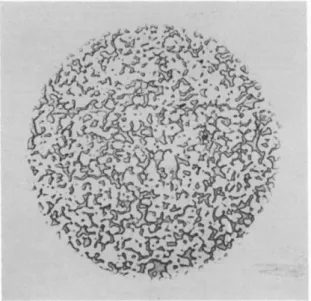
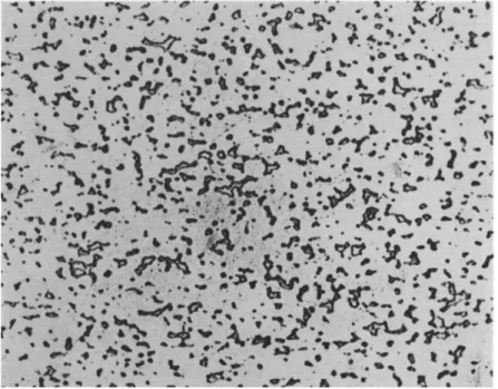
Photomicrographs of certain of these alloys are shown in Figs. 4, 5, and 6. Figure 4 (alloy B) shows a chill-cast phosphor-bronze, with a
196 P . G. F O R R E S T E R
COPPER IO 2 0 3 0 4 0 5 0 % LEAD —
F I G . 3. Compositions of some standard copper-lead-tin alloys.
T A B L E I I
S O M E S T A N D A R D C O P P E R - L E A D - T I N A L L O Y S
Composition code
(see Fig. 3 ) Designations" Notes
A A S T M Β 22 A Casting alloy; contains 1% (minimum) phosphorus Β B S 1400 P B 4 C Sand-cast, chill-cast, or continuously cast; con
tains 0 . 5 % minimum phosphorus
C S A E 791 Rolled or wrought
D A S T M Β 22 C \ Casting alloy, including sand-cast, chill-cast and B S 1400, L B 2 I J continuously cast
S A E 793 S A E 797
Cast onto steel 1TT „ , , .
c,. , , , , , > usually for split bushes Sintered onto steel J
Ε B S 1400 L B 5 I Sand-cast, chill-cast, or continuously cast S A E 794 Cast onto steel \ F o r split bushes and half-
S A E 799 Sintered onto steel / bearings
F S A E 48 Cast or sintered onto steel, for half-bearings G S A E 480 Cast or sintered onto steel, for half-bearings
0 A S T M refers to American Society for Testing and Materials; S A E refers to the Society of Automotive Engineers; B S refers to British Standards.
cored and solid solution of tin in copper, and a complex of copper-tin and copper-phosphorus compounds. Figure 5 (alloy D) shows a chill- cast 80% copper-10% lead-10% tin alloy, showing a similar structure to B, but with the addition of a separate lead phase, occurring as isolated spheres. Figure 6 (alloy F ) shows a sintered 70% copper-30% lead alloy, consisting of two continuous interlocking phases of substantially pure copper and lead.
At one time it was almost a conditioned reflex for designers to specify phosphor-bronze for any general-purpose bearing application, and the term "bronze" is still occasionally used as synonymous with
"bearing." In recent years, however, the tendency has been to specify
M A T E R I A L S F O R P L A I N B E A R I N G S 197
F I G . 4. Microstructure of chill-cast bronze containing 11% tin and 0.1% phos
phorus ( X 3 0 0 ) .
F I G . 5. Microstructure of chill-cast bronze containing 10% tin and 10% lead ( X 1 0 0 ) .