ISSN 1998-0124 CN 11-5974/O4
2021, 14(5): 1450–1456 https://doi.org/10.1007/s12274-020-3201-2
Research Art
Lightweight porous silica foams with extreme-low dielectric permittivity and loss for future 6G wireless communication technologies
Petra S. Pálvölgyi1, Daniel Sebők2, Imre Szenti2, Eva Bozo1, Henri Ervasti1, Olli Pitkänen1, Jari Hannu1, Heli Jantunen1, Marko E. Leinonen3, Sami Myllymäki1, Akos Kukovecz2 (), and Krisztian Kordas1 ()
1 Microelectronics Research Unit, Faculty of Information and Electrical Engineering, University of Oulu, P. O. Box 4500, FI-90570 Oulu, Finland
2 Interdisciplinary Excellence Centre, Department of Applied and Environmental Chemistry, University of Szeged, Rerrich Béla tér 1, H-6720 Szeged, Hungary
3 Centre for Wireless Communications, University of Oulu, P. O. Box 4500, FI-90570 Oulu, Finland
© The Author(s) 2020
Received: 31 July 2020 / Revised: 1 October 2020 / Accepted: 15 October 2020
ABSTRACT
In the next generation wireless communication systems operating at near terahertz frequencies, dielectric substrates with the lowest possible permittivity and loss factor are becoming essential. In this work, highly porous (98.9% ± 0.1%) and lightweight silica foams (0.025 ± 0.005 g/cm3), that have extremely low relative permittivity (εr = 1.018 ± 0.003 at 300 GHz) and corresponding loss factor (tan δ < 3 × 10⁻⁴ at 300 GHz) are synthetized by a template-assisted sol-gel method. After dip-coating the slabs of foams with a thin film of cellulose nanofibers, sufficiently smooth surfaces are obtained, on which it is convenient to deposit electrically conductive planar thin films of metals important for applications in electronics and telecommunication devices. Here, micropatterns of Ag thin films are sputtered on the substrates through a shadow mask to demonstrate double split-ring resonator metamaterial structures as radio frequency filters operating in the sub-THz band.
KEYWORDS
low-permittivity materials, low-loss dielectrics, templated sol-gel synthesis, silica foams, 6G telecommunication
1 Introduction
In a fully data-centric world populated with telecommunication devices of autonomous vehicles, sensors, robots and cloud resources connected, networks need to transfer greater amount of data than that the currently used 4G and 5G systems are capable of handling. To meet the requirements, such as extraordinary level of data reliability, low latency, low power consumption and massive capacity, devices of the next generation 5G and 6G wireless communication technologies are expected to use millimeter wave bands (30–300 GHz) [1–6].
These high frequencies imply extreme device densities with small size and immunity for interference, thus urging the development new materials with unique properties and structures with unorthodox design [7, 8].
In radio frequency (RF) devices, dielectric materials are used as substrates of filters, resonators and antennas. Signal distortion, noise and power consumption are determined by wave propagation delay and attenuation, that among others, depend on the relative permittivity (εr) and loss factor (tan δ), and thus minimizing those is one of the keys for enabling or improving device performance [9–13]. For wireless com- munication technologies, several dielectric materials, such as polymers, ceramics and their composites have been applied.
Polymers can offer relatively low εr but usually have high tan δ.
On the contrary, ceramics have intrinsically higher εr and in that case, very moderate tan δ [9, 13, 14]. Applying porous dielectrics, both εr and tan δ can be reduced (although with the expense of mechanical strength and thermal conductivity, which may limit their use in some applications) [15]. Using effective medium approximations, the apparent permittivity of heterogeneous (multiphase) materials can be estimated considering the microstructure as well as the volume fraction and the dielectric permittivity of the phases [16].
Several mature technologies exist for producing porous dielectric materials, that have been widely exploited in chemistry [17–19], biomedical [20, 21], sensor [22, 23], environmental [24, 25] and optical [26] applications for decades. For micro- and millimeter wave RF applications, porous materials have not been explored in detail, although the interest in dielectrics with low permittivity and loss is gradually being addressed in recent studies. Porous films of polyimide (εr = 1.7 at 18 GHz) were made by controlled evaporation of N-methylpyrrolidone solvent from polymer solutions [27]. Methylsiloxane synthesized by a sol-gel route from methyltrimethoxysilane in methanol also resulted in a porous product (εr = 1.4–1.6 at 60 GHz) [28].
Porous poly(methyl methacrylate) was shown to form (εr = 3.6 at 1 kHz) in a solid-state foaming process using high pressure CO2 dissolution and low pressure release [29]. Incomplete but well-controlled sintering of microscopic or nanoparticles of Address correspondence to Akos Kukovecz, kakos@chem.u-szeged.hu; Krisztian Kordas, krisztian.kordas@oulu.fi
ceramics could also result in porous structures. For instance, microparticles of Si3N4 sintered with a gel binder in the presence of dispersed polystyrene spheres form a solid three-dimensional (3D) network with voids (εr = 2.3–4.3, tan δ = 1.2×10⁻³–1.5×10⁻³ at 15 GHz) [30]. In a similar fashion but without using sacrificial polystyrene template, porous boron nitride/silicon oxynitride was demonstrated (εr = 3.83 and tan δ = 0.008 at 21–38 GHz frequency band) by sintering their sub-micrometer size particles without densification in the presence of Li2O glass forming aid [31].
Among dielectrics, silica is one of the most convenient material for high frequency applications due to its thermal and chemical stability, mechanical strength, low cost, moderate permittivity and very low loss factor, which suggest its use in porous structures to obtain dielectrics with ultimate properties [10]. As demonstrated in earlier studies, porous structures of silica can be obtained by a large variety of sol-gel methods based on alkyl silane precursor chemistries using supercritical [32]
and freeze drying [33] as well as by template-assisted synthesis on colloidal polystyrene polymers [34, 35] and surfactants [36].
Furthermore, very lately, we have shown that sol-gel silica nanoshells synthesized on polystyrene nanobead sacrificial templates may be assembled into highly porous 3D networks with the help of cellulose nanofibers resulting in composites with very low dielectric permittivity and loss (εr = 1.19 ± 0.01 and tan δ = 0.011 ± 0.001 at 300 GHz) [37].
In this work, we present a novel highly porous silica foam structure with extremely low dielectric permittivity and loss factor being close to that of air. The silica foams were synthesized on sacrificial 3D carbon foam templates using sol-gel chemistry.
The surface of the silica foams is reinforced with cellulose nanofiber thin films to create a smooth coating suitable for post metallization. The feasibility of the as-obtained materials for high frequency RF applications are demonstrated by sputtering Ag micropatterns of double split ring resonator (DSRR) arrays operating as planar frequency band filters at 300 GHz.
2 Experimental
2.1 Materials
Melamine foam (BASF Basotect® W), ethanol (EtOH, 99.5 wt.%, Altia), ammonium hydroxide solution (NH4OH, 25 wt.%, Sigma-Aldrich) and tetraethyl orthosilicate (TEOS, ≥ 99%, Sigma-Aldrich) were used as received. Cellulose nanofibers were synthesized as described earlier [37].
2.2 Porous silica foam synthesis
First, the carbon foam was prepared by a pyrolysis of melamine foam in a 4” quartz tube furnace under N2 flow (150 mL/min). The furnace was heated to 300 °C at a rate of 15 °C/min, then to 800 °C at a rate of 2 °C/min, and kept there for 60 min [38–40]. Next, a thin silica shell was synthesized on the carbon skeleton by base catalyzed sol-gel polycondensation of TEOS. The carbon foams were cut to a size of about 15 mm × 15 mm × 3 mm and placed in a mixture of 26 mL EtOH and 3 mL of NH4OH. After 5 min, 2 mL TEOS was added, and the carbon foam was kept in the reaction mixture for 2 h at 23 °C.
The silica coated foam products were washed with EtOH and dried for 2 h in an oven at 50 °C. To make sure silica is completely coating the carbon skeleton, the sol-gel process was repeated two times, after which the samples were annealed in a tube furnace at 800 °C in air for 2 h to burn off the carbon skeleton and simultaneously to calcine the silica gel.
2.3 Cellulose nanofiber coated silica foam
To provide a smooth envelope of the silica foam, the foams were immersed into cellulose nanofiber (0.1 wt.%) suspension and removed at once, the foams were then placed between two release foils and aluminum plates to preserve the straightness of the sides during the drying, then put in box furnace, heated to 105 °C and left there for 2 h.
2.4 Planar filter structures
Arrays of planar double split-ring resonators were designed by CST Studio Suite electromagnetic simulation software and the patterns were sputtered (Ag, 500 nm, deposition conditions:
95 W, 2.9 Å/s deposition rate, Ar atmosphere, p = 2.4 mTorr) on the cellulose coated silica foam through a laser-cut shadow mask. The layout of the structure is shown in Fig. S1 in the Electronic Supplementary Material (ESM). A sample cross- section analyzed by FESEM show that most of the sputtered Ag is located on the surface of the nanocellulose coating but EDX analysis reveals that Ag has also penetrated into the porous nanocellulose film (Fig. S2 in the ESM).
2.5 Characterization
The micro and crystal structures of the synthesized materials was assessed by field emission scanning electron microscopy (FESEM, Zeiss Ultra Plus), Raman spectroscopy (Horiba Jobin-Yvon LabRAM HR800) and X-ray diffraction (Bruker D8 Discover XRD), respectively. The 3D structure of the samples was obtained via X-ray micro-computed tomography analysis (X-ray Nanotomograph, Bruker SkyScan 2211, Bruker, Belgium).
The whole structure of the sample was scanned using 11 Mp CCD detector by applying source voltage of 80 kV and current of 450 μA with an exposure time of 275 ms (in microfocus mode). The sample was scanned in 180° by employing a rotation step of 0.15° and voxel size of 4.5 μm × 4.5 μm × 4.5 μm. To obtain higher resolution images a smaller part of the sample was also analyzed using the same detector and parameters except for the rotation step size and the voxel size, which were 0.1° and 1.5 μm × 1.5 μm × 1.5 μm, respectively. NRecon reconstruction software (Skyscan, Bruker, Belgium) was used to reconstruct the projected images, CTVox and CTAn softwares (Skyscan, Bruker, Belgium) were applied for visualizing the 3D-rendered objects and to carry out the 3D object analysis.
The dielectric properties of composite foams and filter evaluation were determined from terahertz transmission spectroscopy measurements (Terapulse 4000, 0.1–2 THz) applying a rectangular metal aperture of 5.0 nm × 5.0 mm size in the path of the incident laser beam. The measured transmitted amplitude values were compared to air as reference, and the real and imaginary parts of dielectric permittivity and loss factor were calculated from the Fourier-transformed amplitude. In the comparison as a reference of filter measurements, simulated results were added.
The density and porosity of the foams were calculated from the dimensions and weight measurements. The effective permittivity (εMG) values were calculated by the Maxwell Garnett mixing formula
h i h
MG h
h i h
1 2
( )
1 3
( )
3
ε f ε ε
ε ε
ε f ε ε
+ + -
= -
+ - (1) where εh and εi denote the relative permittivity of host medium and inclusions, respectively; and f is the volume filling factor [47].
The volume of the components in the samples were calculated from wt.% and densities of those, from which volume filling
factors were evaluated. First the effective permittivity of solid phase was calculated from the equation (where εh = 4.3 and εi = 3.0 correspond to dielectric permittivity of bulk silica and cellulose). The value evaluated in this way served as εi and permittivity of air as εh in the solid-gaseous system.
3 Results and discussion
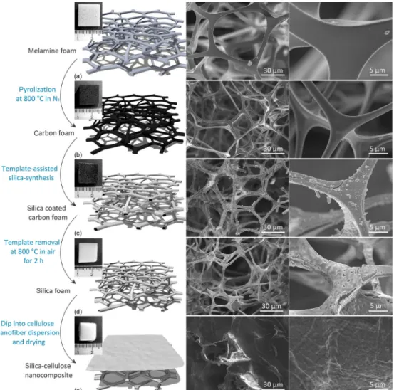
Highly porous silica foam was obtained by sol-gel synthesis on sacrificial carbon foam template, prepared by pyrolization of melamine foam. During the carbonization, melamine foam shrank about 10% in volume and changed its color from pale gray to black (Fig. 1). The resulting carbon foam remained elastic and kept the original skeletal structure. After the carbonization process, a thin continuous silica shell was deposited on the skeleton by a base catalyzed sol-gel polymerization of the silica precursor. Light weight silica foams (ρ = 0.026 ± 0.001 g/cm3 and porosity of 98.9% ± 0.1% according to gravimetric analysis) having interconnected hollow skeletal nanotubes in their structure were obtained by annealing the gel coated carbon foam at 800 °C in air for 2 h, which resulted in a simultaneous burning off of the carbonaceous core and calcination of the silica gel. In the course of the calcination process, the volume of the silica foam became about 35% smaller in reference to the gel coated carbon foam.
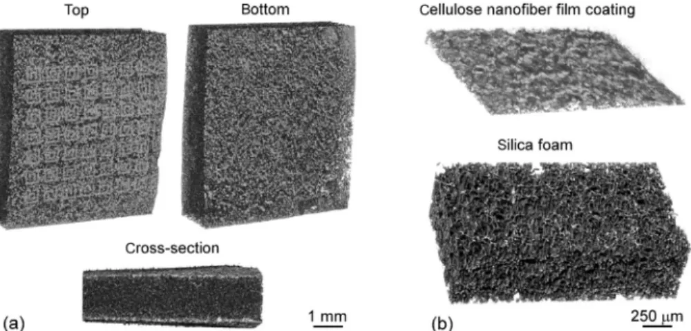
The pore structures of the silica foam and the nanocellulose
film envelopes are clearly visible in constructed 3D models obtained by high resolution computed tomography (μ-CT) in Fig. 2. Calculations based on the μ-CT data give porosity being higher than 90%. It is important to mention that this value is underestimated, since pores below 4.5 μm3 (e.g. the cavities in the silica skeleton at the places of the sacrificial carbon skeleton template, what was burned off) are undetectable with this technique and measurement parameters.
The presence of silica product and the complete removal of the carbonaceous template is confirmed by Raman spectroscopy (Fig. 3(a)). Peaks associated with silica are visible at 228 cm−1 (Si–O–Si bending and torsional/twisting modes), 415 cm−1 (O–Si–O bending) as well as at 785 and 1,076 cm−1 (stretching vibration of Si–O) [41, 42], whereas no signatures of carbon are found in the spectrum (missing the D and G bands of carbon at 1,350 and 1,590 cm−1, respectively). X-ray diffraction analysis of the product shows a strong reflection at around 21.6° and three weaker ones at 28.2°, 31.0° and 35.8° 2θ angles indicating that the silica shell is crystalline (SiO2, cristobalite phase) and have a volume averaged crystal diameter of ~ 11.5 ± 1.0 nm as calculated from the broadening of the peaks (Fig. 3(b)) [43, 44].
Since the pores in the silica foam are having too large size (diameter of ~ 30 μm) to deposit micropatterns of any planar metal thin films on the surface, the silica foams were coated with a thin envelope film of cellulose nanofibers. This was
Figure 1 Sequence of cellulose nanofiber coated silica foam synthesis showing each intermediate material in camera, computer generated and SEM images of lower and higher magnification. (a) Melamine foam, which is pyrolyzed to obtain (b) sacrificial carbon foam template. (c) Silica coated carbon foam made by template-assisted sol-gel synthesis. (d) Silica foam with hollow wires in its skeleton obtained by burning off the sacrificial carbon template.
(e) Cellulose nanofiber coated silica foam used as substrate material having ultra-low dielectric permittivity and loss tangent in this work. Note: the lower magnification SEM image shows a manually scratched part of the cellulose coating to revealing the silica foam beneath.
achieved by immersing the silica foam samples into a cellulose nanofiber suspension from which the nanofibers sediment and clog the voids on the surface forming a thin continuous film, which after drying, is suitable for post metallization. The density of the obtained silica-cellulose composite is ρ = 0.025 ± 0.005 g/cm3, calculated from dimension and mass measurements with a corresponding composition of 78.8 wt.% ± 3.7 wt.% silica and 21.2 wt.% ± 3.7 wt.% cellulose.
The silica foams are fragile and relatively soft. Mechanical measurements show very small Young modulus (~ 20 kPa) below 10% strain, which is somewhat higher (~ 400 kPa) upon larger deformations (Fig. S3(a) in the ESM). Since substrate type materials require reasonable mechanical strength in practical devices, here we apply a 3D printed plastic frame in which the slabs can be enclosed. Such framed slabs can withstand large load forces, thus providing protection for the functional com- ponent making the structure practical for further integration into any application (Fig. S3(b) in the ESM).
The thermal conductivity of the foams is extremely low (estimated to be below 2 × 10⁻³ W·m−1·K−1), which means that any absorbed electromagnetic power can be dissipated only through convection and radiation. However, considering that the typical absorbed power levels e.g. in filter applications (that we are demonstrating in this work) are not higher than 0.1 mW for devices with size similar to ours, the calculated temperature rise in the component is insignificant, only ~ 0.4 °C (for the calculation, see the ESM). This means that the low thermal conductivity of such foams is not limiting their applications in RF filters.
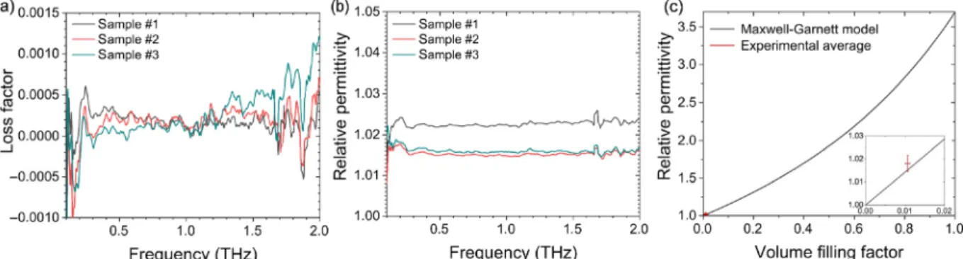
The dielectric permittivity of the foams measured up to 2 THz is extremely low (εr = 1.018 ± 0.003 at 300 GHz, and similar in
the entire frequency window), nearly close to that of air. The value of deduced loss factor is also extremely low, practically within the error of the measurement (tan δ < 3 × 10⁻⁴ at 300 GHz).
These results are plausible considering the very high porosity of the samples. According to the Maxwell-Garnett effective medium approximation model, the relative dielectric permittivity calculated from the permittivity values and filling factors of the components of the composite is εr = 1.016, which is in great agreement with the experimental data (Fig. 4). (Measurements carried out at mm-wave frequencies from 4 to 20 GHz are very similar to those we obtained above 100 GHz showing the relative permittivity is scattering around ~ 1.02 with a corresponding loss tangent of ~0.002 as displayed in Fig. S4 in the ESM).
Frequency filters are used in mobile telecommunication systems to reduce interference of adjacent bands and to avoid out-of-band spurious signals of transceivers, thus ensuring optimum radio performance. Meta-surface band pass filters are physically located in the close proximity of the transceiver, where the signal is propagating in the free space. Accordingly, substrates with ultimately low εr and tan δ are required and the pattern definition of the conductive metamaterial structures shall be of high quality to ensure low insertion loss, low ripple, and high stop-band attenuation in the filter. As the highly porous nanocellulose coated silica foams we developed suggest ideal dielectric properties for substrates of metamaterial surface structure based planar filter, we designed periodic arrays of double split-ring-resonators (DSRRs) composed of two concentric metallic rings with opposite splits (Fig. S1 in the ESM). The DSRR element is coupled to a magnetic field component of the propagating wave oscillating in the axial
Figure 2 Computed tomography images of (a) cellulose nanofiber coated silica foam. On the surface of the sample (in the top view image) the periodic array structure of double split-ring-resonators (DSRRs) sputtered on the surface is visible. (b) High resolution scans of the nanofiber film and the silica foam.
Figure 3 (a) Raman spectrum and assigned vibration modes of silica. (b) XRD pattern of the synthesized silica foam with the corresponding reflections of cristobalite.
direction and establishing a current flow that induces a magnetic dipole parallel or antiparallel to the magnetic field [45, 46].
Periodic arrays of DSRRs may be produced with good repeatability and throughput on the porous surfaces by sputtering Ag through a shadow mask according to optical microscopy analysis (Fig. 5(a) and Fig. S5 in the ESM). Because of the good accuracy of the line width definition (±10% within the actual patterns, and ±5% between filter samples) the transmittance spectra of several DSRR filter structures measured at 100–500 GHz (Figs. 5(b) and 5(c) and Fig. S5 in the ESM) are nearly identical and the measured pass band at 240–300 GHz with a transmittance of 90% show very good match with the corresponding simulation data (240–310 GHz and 95%). It is worth mentioning that the variations of permittivity values of the substrates used are expected to cause only very minor changes (1%) in the transmittance response according to our simulations. Furthermore, the transmittance spectra of the filters measured at a sample position rotated with 90 degree compared to the first set of measurements show a narrowed pass band and 270–300 GHz and broadened stop band at lower frequencies (210–260 GHz). The difference of the transmission spectra between the original and 90° rotated positions is plausible considering the symmetry of the DSRR structures, and such characteristics could actually be beneficial in radio systems utilizing polarized waves.
4 Conclusions
In conclusion, lightweight, porous silica foam slabs were synthesized by sol-gel synthesis on sacrificial templates of
carbon foams. The highly porous silica foams were coated with a thin film of cellulose nanofibers to make the surface smooth thus suitable for post metallization and feasible to use as substrate materials. Owing to their very high porosity (98.9% ± 0.1%) the dielectric permittivity and loss factor of the cellulose nanofiber coated silica foams measured up to 2.0 THz were found extremely low (εr = 1.018 ± 0.003 and tan δ < 3 × 10⁻⁴ at 300 GHz, and similar in the entire spectrum) practically very close to those of air. The structures could be used as substrates for sputtering micropatterns of dual split-ring resonator arrays operating as band pass filters at the sub-THz frequency band of future 6G telecommunication systems.
Conflict of interest
Some of the authors of the paper (Petra S. Pálvölgyi, Olli Pitkänen, Heli Jantunen, Sami Myllymäki, Krisztian Kordas) and their institution filed an intellectual property (application number 20205944, Finnish Patent and Registration Office).
The application covers the details of the synthesis, properties, and RF applications of the porous substrate material.
Acknowledgements
The authors thank Kai Metsäkoivu for the technical assistance and Henrikki Liimatainen for providing us with nanocellulose materials. The financial support received partly from EU Interreg Nord–Lapin liitto (project Transparent, conducting and flexible films for electrodes), Academy of Finland (6Genesis Flagship under Grant 318927), University of Oulu (projects Entity and PoC: Ultra-low permittivity and loss porous nanocomposites
Figure 4 (a) Loss factor and (b) relative dielectric permittivity of silica-cellulose nanocomposite films measured from 100 GHz to 2 THz (curves are smoothened by adjacent-averaging using 10 points of window). (c) Experimental value of dielectric permittivity of porous silica-cellulose nanocomposite (at THz region) and calculated relative permittivity values for different porosities using the Maxwell-Garnett approximation.
Figure 5 (a) Optical micrograph of DSRR structures. The width of lines and corners are 98 ± 9 and 77 ± 6 μm, respectively; and the Ag micropatterns in 80% of the DSSR structures in the filter were intact. (b) Camera image of a filter device. (c) Schematic drawing of the THz spectroscopy setup. (d) Experimental and simulated high frequency transmission spectra of the filter structure at sample positions of 0° and 90° (rotated in the x–yplane). Note:
In our THz spectroscopy setup, when the frequency is low, the diameter of the probe beam grows larger than the limiting aperture making the eventual measurement less accurate (increased transmission) thus deviating from the simulations, which is particularly apparent at frequencies below 200 GHz.
for future 6G telecommunication), Hungarian National Research, Development and Innovation Office through the projects GINOP-2.3.2-15-2016-00013 and GINOP-2.3.3-15-2016-00010, and the Ministry of Human Capacities, Hungary, grant 20391-3/2018/FEKUSTRAT is acknowledged. D. S. is thankful for the János Bolyai Research Scholarship of the Hungarian Academy of Sciences.
Funding note: Open access funding provided by University of Szeged
Electronic Supplementary Material: Supplementary material (layout and optical micrographs of the double split-ring resonator array, high frequency transmission spectra of filter devices (0.1-1.5 THz), low frequency permittivity and loss of the silica foam (at 4–20 GHz), FESEM/EDX analysis of the cross-section of chips and mechanical properties of the silica foam) is available in the online version of this article at https://doi.org/10.1007/s12274-020-3201-2.
Open Access This article is licensed under a Creative Commons Attribution 4.0 International License, which permits use, sharing, adaptation, distribution and reproduction in any medium or format, as long as you give appropriate credit to the original author(s) and the source, provide a link to the Creative Commons licence, and indicate if changes were made.
The images or other third party material in this article are included in the article’s Creative Commons licence, unless indicated otherwise in a credit line to the material. If material is not included in the article’s Creative Commons licence and your intended use is not permitted by statutory regulation or exceeds the permitted use, you will need to obtain permission directly from the copyright holder.
To view a copy of this licence, visit http://creativecommons.org/licenses/by/4.0/.
References
[1] Cabrol, P.; Pietraski, P. 60 GHz patch antenna array on low cost Liquid-Crystal Polymer (LCP) substrate. In Proceedings of 2014 IEEE Long Island Systems, Applications and Technology (LISAT), Farmingdale, NY, USA, 2014, pp 1–6.
[2] Park, S. J.; Shin, D. H.; Park, S. O. Low side-lobe substrate-integrated- waveguide antenna array using broadband unequal feeding network for millimeter-wave handset device. IEEE Trans. Antennas Propag.
2015, 64, 923–932.
[3] Rappaport, T. S.; Sun, S.; Mayzus, R.; Zhao, H.; Azar, Y.; Wang, K.;
Wong, G. N.; Schulz, J. K.; Samimi, M.; Gutierrez, F. Millimeter wave mobile communications for 5G cellular: It will work! IEEE Access 2013, 1, 335–349.
[4] Song, H. J.; Nagatsuma, T. Present and future of terahertz communications.
IEEE Trans. Terahertz Sci. Technol. 2011, 1, 256–263.
[5] Giordani, M.; Polese, M.; Mezzavilla, M.; Rangan, S.; Zorzi, M.
Toward 6G networks: Use cases and technologies. IEEE Commun.
Mag. 2020, 58, 55–61.
[6] Chowdhury, M. Z.; Shahjalal, M.; Hasan, M. K.; Jang, Y. M. The role of optical wireless communication technologies in 5G/6G and IoT solutions: Prospects, directions, and challenges. Appl. Sci. 2019, 9, 4367.
[7] Waterhouse, R.; Novack, D. Realizing 5G: Microwave photonics for 5G mobile wireless systems. IEEE Microw. Mag. 2015, 16, 84–92.
[8] Duan, B. Y. Evolution and innovation of antenna systems for beyond 5G and 6G. Front. Inf. Technol. Electron. Eng. 2020, 21, 1–3.
[9] Imai, Y. Nanoparticle technology handbook. In Ceramic Fillers for High Frequency Dielectric Composites. 2018; pp 619–623.
[10] Yu, S. Z.; Wong, T. K. S.; Pita, K.; Hu, X. Synthesis of organically modified mesoporous silica as a low dielectric constant intermetal dielectric. J. Vac. Sci. Technol. B 2002, 20, 2036–2042.
[11] Sebastian, M. T.; Ubic, R.; Jantunen, H. Low-loss dielectric ceramic materials and their properties. Int. Mater. Rev. 2015, 60, 392–412.
[12] Sebastian, M. T.; Jantunen, H. Polymer-ceramic composites of 0–3 connectivity for circuits in electronics: A review. Int. J. Appl. Ceram.
Technol. 2010, 7, 415–434.
[13] Baker-Jarvis, J. R.; Janezic, M. D.; Riddle, B. F.; Holloway, C. L.;
Paulter, N. G. Jr.; Blendell, J. Dielectric and conductor-loss charac- terization and measurements on electronic packaging materials.
NIST Tech. Note 1520 2001, 152.
[14] Volksen, W.; Miller, R. D.; Dubois, G. Low dielectric constant materials. Chem. Rev. 2010, 110, 56–110.
[15] Baklanov, M. R.; Maex, K. Porous low dielectric constant materials for microelectronics. Philos. Trans. Roy. Soc. A Math. Phys. Eng.
Sci. 2006, 364, 201–215.
[16] Gershon, D.; Calame, J. P.; Birnboim, A. Complex permittivity measurements and mixings laws of alumina composites. J. Appl.
Phys. 2001, 89, 8110–8116.
[17] Kordás, K.; Tóth, G.; Levoska, J.; Huuhtanen, M.; Keiski, R.;
Härkönen, M.; George, T. F.; Vähäkangas, J. Room temperature chemical deposition of palladium nanoparticles in anodic aluminium oxide templates. Nanotechnology 2006, 17, 1459–1463.
[18] Lee, I.; Zhang, Q.; Ge, J. P.; Yin, Y. D.; Zaera, F. Encapsulation of supported Pt nanoparticles with mesoporous silica for increased catalyst stability. Nano Res. 2011, 4, 115–123.
[19] Guan, B. Y.; Wang, T.; Zeng, S. J.; Wang, X.; An, D.; Wang, D. M.; Cao, Y.; Ma, D. X.; Liu, Y. L.; Huo, Q. S. A versatile cooperative template- directed coating method to synthesize hollow and yolk-shell mesoporous zirconium titanium oxide nanospheres as catalytic reactors. Nano Res. 2014, 7, 246–262.
[20] Wang, L.; Zhao, W. J.; Tan, W. H. Bioconjugated silica nanoparticles:
Development and applications. Nano Res. 2008, 1, 99–115.
[21] Chiang, Y. C.; Lin, H. P.; Chang, H. H.; Cheng, Y. W.; Tang, H. Y.;
Yen, W. C.; Lin, P. Y.; Chang, K. W.; Lin, C. P. A mesoporous silica biomaterial for dental biomimetic crystallization. ACS Nano 2014, 8, 12502-12513.
[22] Li, Y. Y.; Cunin, F.; Link, J. R.; Gao, T.; Betts, R. E.; Reiver, S. H.;
Chin, V.; Bhatia, S. N.; Sailor, M. J. Polymer replicas of photonic porous silicon for sensing and drug delivery applications. Science 2003, 299, 2045–2047.
[23] Shopsowitz, K. E.; Qi, H.; Hamad, W. Y.; MacLachlan, M. J. Free- standing mesoporous silica films with tunable chiral nematic structures. Nature 2010, 468, 422–425.
[24] Feng, X.; Fryxell, G. E.; Wang, L. Q.; Kim, A. Y.; Liu, J.; Kemner, K. M. Functionalized monolayers on ordered mesoporous supports.
Science 1997, 276, 923–926.
[25] Yu, S. J.; Li, W.; Fujii, Y.; Omura, T.; Minami, H. Fluorescent spherical sponge cellulose sensors for highly selective and semiquantitative visual analysis: Detection of Hg2+ and Cu2+ ions. ACS Sustainable Chem. Eng. 2019, 7, 19157–19166.
[26] Mandal, J.; Fu, Y. K.; Overvig, A. C.; Jia, M. X.; Sun, K. R.; Shi, N.
N.; Zhou, H.; Xiao, X. H.; Yu, N. F.; Yang, Y. Hierarchically porous polymer coatings for highly efficient passive daytime radiative cooling. Science 2018, 362, 315–319.
[27] Ren, Y.; Lam, D. C. C. Low temperature processable ultra-low dielectric porous polyimide for high frequency applications. In International Conference on Electronic Materials and Packaging, 2006, pp 1–5.
[28] Tanaka, T.; Kawakami, N.; Hirano, T.; Fukumoto, Y.; Suzuki, T.;
Kanamori, K.; Nakanishi, K. Porous Methylsiloxane gel thick film for millimeter-wave antenna substrate prepared by gap filling method.
Mater. Res. Soc. 2006, 888, DOI: 10.1557/PROC-0888-V09-17.
[29] Notario, B.; Pinto, J.; Verdejo, R.; Rodríguez-Pérez, M. A. Dielec- tric behavior of porous PMMA: From the micrometer to the nanometer scale. Polymer 2016, 107, 302–305.
[30] Yin, S.; Pan, L. M.; Huang, K.; Qiu, T.; Yang, J. Porous Si3N4
ceramics with hierarchical pore structures prepared by gelcasting using DMAA as gelling agent and PS as pore-forming agent. J.
Alloys Compd. 2019, 805, 69–77.
[31] Sun, Y. S.; Yang, Z. H.; Cai, D. L.; Li, Q.; Li, H. L.; Wang, S. J.; Jia, D.
C.; Zhou, Y. Mechanical, dielectric and thermal properties of porous boron nitride/silicon oxynitride ceramic composites prepared by pressureless sintering. Ceram. Int. 2017, 43, 8230–8235.
[32] Kawakami, N.; Fukumoto, Y.; Kinoshita, T.; Suzuki, K.; Inoue, K. I.
Preparation of highly porous silica aerogel thin film by supercritical drying. Jpn. J. Appl. Phys. 2000, 39, L182.
[33] Hyun, S. H.; Kim, T. Y.; Kim, G. S.; Park, H. H. Synthesis of Low-k porous silica films via freeze drying. J. Mater. Sci. Lett. 2000, 19, 1863–1866.
[34] Dobó, D. G.; Berkesi, D.; Kukovecz, Á. Morphology conserving aminopropyl functionalization of hollow silica nanospheres in toluene. J. Mol. Struct. 2017, 1140, 83–88.
[35] Velev, O. D.; Jede, T. A.; Lobo, R. F.; Lenhoff, A. M. Porous silica via colloidal crystallization. Nature 1997, 389, 447–448.
[36] Kuang, D. B.; Brezesinski, T.; Smarsly, B. Hierarchical porous silica materials with a trimodal pore system using surfactant templates.
J. Am. Chem. Soc. 2004, 126, 10534–10535.
[37] Pálvölgyi, P. S.; Nelo, M.; Pitkänen, O.; Peräntie, J.; Liimatainen, H.;
Myllymäki, S.; Jantunen, H.; Kordas, K. Ultra-low permittivity porous silica-cellulose nanocomposite substrates for 6G telecommunication.
Nanotechnology 2020, 31, 435203.
[38] Pitkänen, O.; Tolvanen, J.; Szenti, I.; Kukovecz, Á.; Hannu, J.;
Jantunen, H.; Kordas, K. Lightweight hierarchical carbon nano- composites with highly efficient and tunable electromagnetic interference shielding properties. ACS Appl. Mater. Interfaces 2019, 11, 19331–19338.
[39] Pham, T. N.; Sharifi, T.; Sandström, R.; Siljebo, W.; Shchukarev, A.;
Kordas, K.; Wågberg, T.; Mikkola, J. P. Robust hierarchical 3D carbon foam electrode for efficient water electrolysis. Sci. Rep. 2017, 7, 6112.
[40] Kordas, K.; Pitkänen, O. Piezoresistive carbon foams in sensing applications. Front. Mater. 2019, 6, 93.
[41] Hu, G. Q.; Li, W. Y.; Xu, J. N.; He, G. J.; Ge, Y. Y.; Pan, Y. S.; Wang, J. R.; Yao, B. D. Substantially reduced crystallization temperature of SBA-15 mesoporous silica in NaNO3 molten salt. Mater. Lett. 2016, 170, 179–182.
[42] Darling, R. S.; Chou, I. M.; Bodnar, R. J. An occurrence of metastable cristobalite in high-pressure garnet granulite. Science 1997, 276, 91–93.
[43] Joni, I. M.; Nulhakim, L.; Vanitha, M.; Panatarani, C. Characteristics of crystalline silica (SiO2) Particles prepared by simple solution method using sodium silicate (Na2SiO3) precursor. J. Phys. Conf. Ser. 2018, 1080, 012006.
[44] Mitra, J.; Ghosh, M.; Bordia, R. K.; Sharma, A. Photoluminescent electrospun submicron fibers of hybrid organosiloxane and derived silica. RSC Adv. 2013, 3, 7591–7600.
[45] Lu, M. Z.; Li, W. Z.; Brown, E. R. Second-order bandpass terahertz filter achieved by multilayer complementary metamaterial structures.
Opt. Lett. 2011, 36, 1071–1073.
[46] Zhu, Y. H.; Vegesna, S.; Kuryatkov, V.; Holtz, M.; Saed, M.; Bernussi, A.
A. Terahertz bandpass filters using double-stacked metamaterial layers. Opt. Lett. 2012, 37, 296–298.
[47] Markel, V. A. Introduction to the Maxwell Garnett approximation:
Tutorial. J. Opt. Soc. Am. A 2016, 33, 1244–1256.